Week 7 - Fluid Sloshing Effect inside Gear Box
AIM :
To study the fluid sloshing effect inside the gear-box for different immersion percentages and fluids
Part 1:
- 20% Immersion, Fluid - Engine oil.
- 30% Immersion, Fluid- Engine oil.
- 20% Immersion,Fluid-n-heptane (c7h16).
- 30% Immersion,Fluid-n-heptane (c7h16).
Part 2:
- What is Dynamic meshing? Give some other examples where dynamic meshing can be used.
- What is the fluid Sloshing effect? Discuss whether the sloshing effect is good or bad? Explain.
- What is the use of UDF?
- Discuss the common errors that occurred in the simulation. A] 'Dynamic mesh failed' error. B] 'Negative cell volume detected' error.
FLUID SLOSHING IN GEARS
Fliuid sloshing is a phenomenon of moving of liquid inside a container due to relative movement between the fluid and some solid part or the container itself.To be a slosh dynamics problem, the liquid must have a free surface where the dynamics of the liquid can interact with the container and dramatically change the dynamics of the system. Important examples are cargo slosh in trucks and ships carrying liquids (such oil and petrol) and propellant slosh in spacecraft tanks and rockets (particularly upper stages).To solve the fluid-structure interaction problem, these kinds of analyses are often performed using computational fluid dynamics and finite element techniques.
The sloshing of fluid (lubricant) in gears enables the spreading of the lubricant evenly to all the teeths of the gear. This simulation is performed to check the right percentage of immersion and fluid used to achieve overall lubrication of the gear, making the gear motion smooth
PART-1 MODELING AND SOLVING
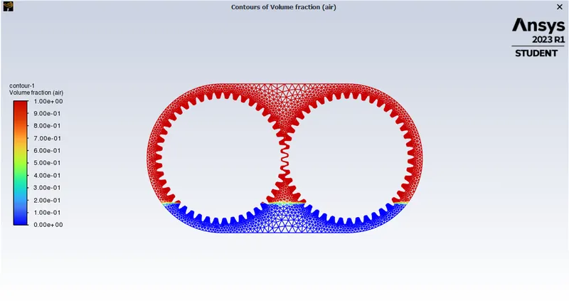
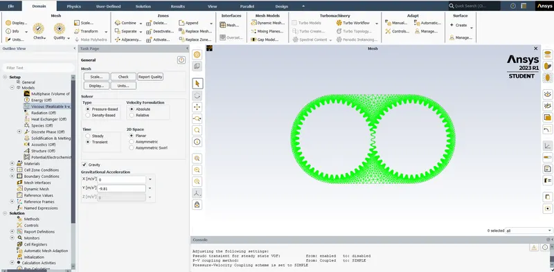
- To simulate the fluid sloshing effect, it essential to use a transient simulation model and allot initial regions of different fluids to the gear-box geometry. To solve for this over a 3D geometry is very time and resource intensive due to which, the problem is reduced to a 2D simulation.
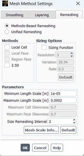
- As, the sloshing will happen as a result of gear motion, it is important to provide the gear motion to the set-up, which will eventually require formation of dynamic mesh to capture the changing zones
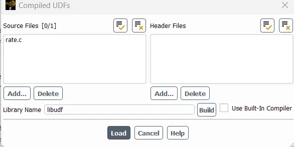
- To provide this gear motion, a UDF i.e. a user defined function is used. This code will direct the motion of the gear
#include "udf.h"

DEFINE_CG_MOTION(right_motion, dt, vel, omega, time, dtime)
{
	vel[0] = 0.0;
	vel[1] = 0.0;
	vel[2] = 0.0;   omega[0] = 0.0;
	omega[1] = 0.0;
	omega[2] = 2.0e2; /* [rad/s]*/
}
DEFINE_CG_MOTION(left_motion, dt, vel, omega, time, dtime)
{
	vel[0] = 0.0;
	vel[1] = 0.0;
	vel[2] = 0.0;

	omega[0] = 0.0;
	omega[1] = 0.0;
	omega[2] = -2.0e2; /* [rad/s]*/
}
- The model is repeated for different fluids ( engine-oil & n-heptane ) and different immersion percentages ( 20% & 30%) to study the effect of material and immersion percentage on the uniform distrbution of the fluid over the teeth of the gears
GEOMETRY
- The workbench is opened through the C++ command prompt
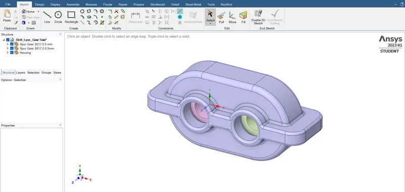
- The gear box gerometry is imported to spaceclaim
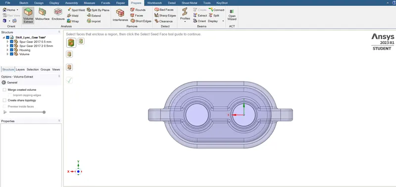
- Extract the volume of the gear-box geometry usinf volume extract tool
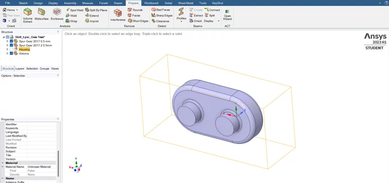
- The three planes are created by hovering on the origin, one of the planes is used to cut the gear box volume into two halves using split body command
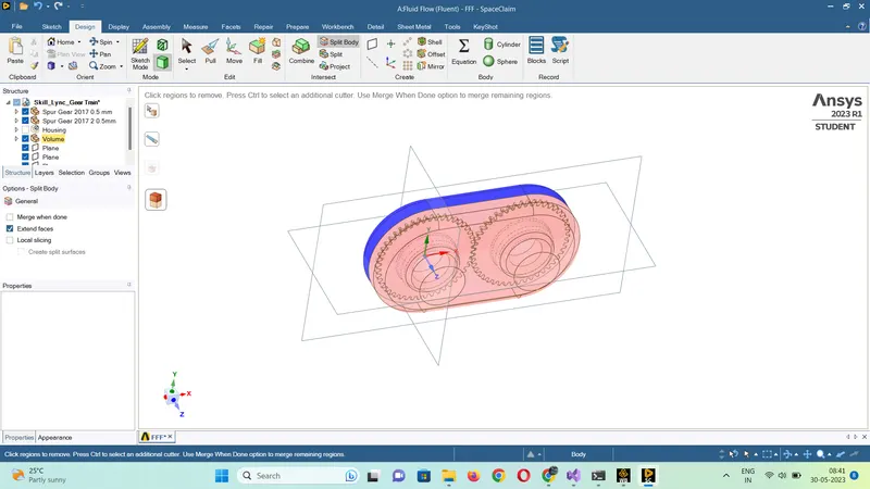
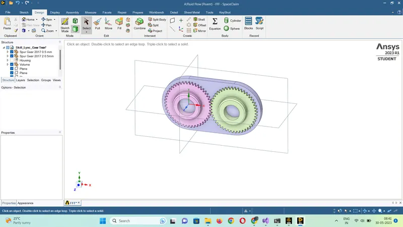
- The cut plane formed is copied and pasted as a surface in another spaceclain file
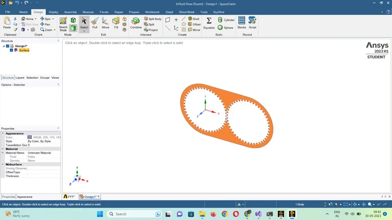
- This is the final surface which will be used for simulation
MESH
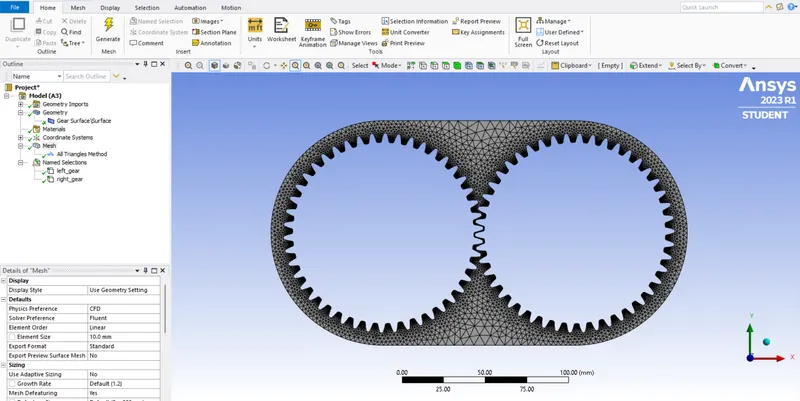
- Geometry is imported in the mesh modeler
- Named selection of right and left gear is made
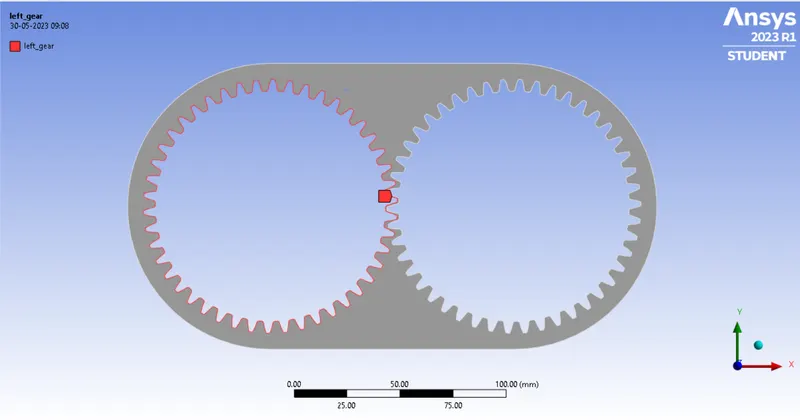
- Element size = 10 mm & All triangles method is used to capture the sharp geomtery accurately
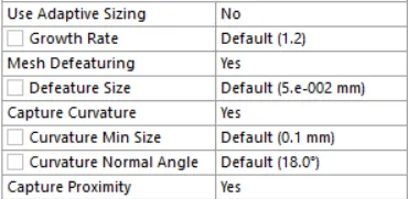
- Capture Proximity - Yes
- No. of elements and nodes

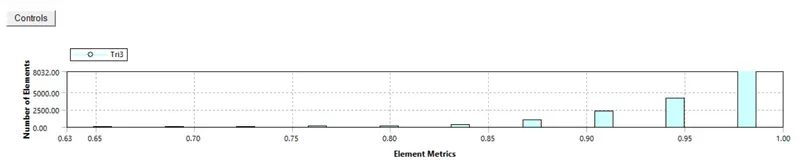
- Element Quality
SET-UP
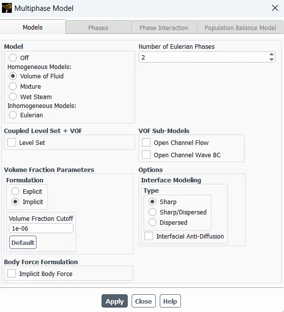
- Model - Discrete Phase Model ( Volume of Fluid Method)
- Turbulence Model - k-epsilon ( realizable - enhanced wall treatment )
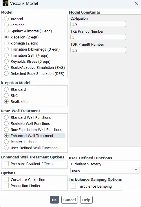
- Solver - Pressure Based ; Time - Transient ; Gravity - 9.81 m/s^2
- Primary Phase - Air
- Secondary Phase - Engine oil / n-heptane
- Import the UDF into the set-up. The rate.c file is loaded
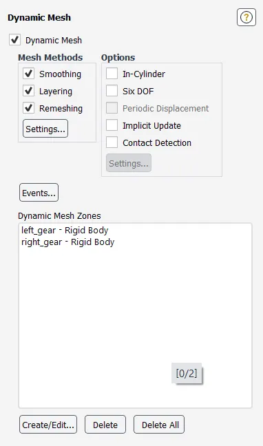
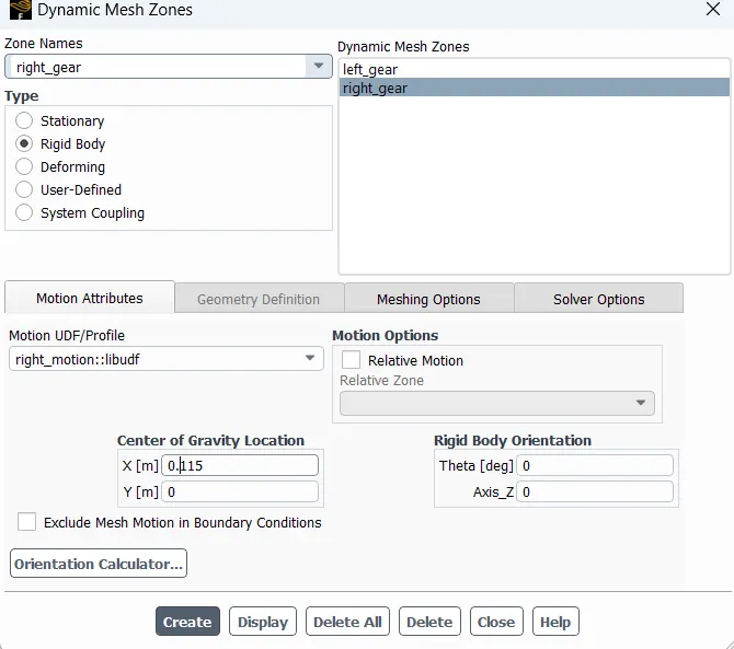
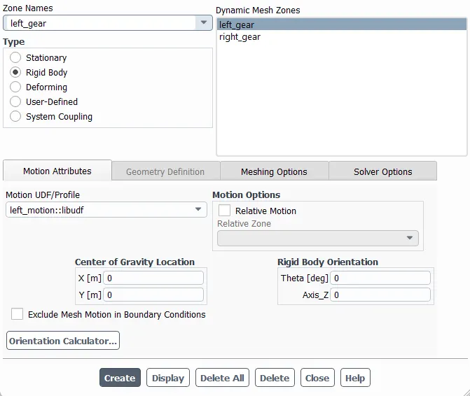
- Dynamic Mesh - Enabled with the following settings, motion of the gear is set using the UDF
- The centre of mass coordinates can be found by viewing properties and centre of volume coordinates in spaceclaim
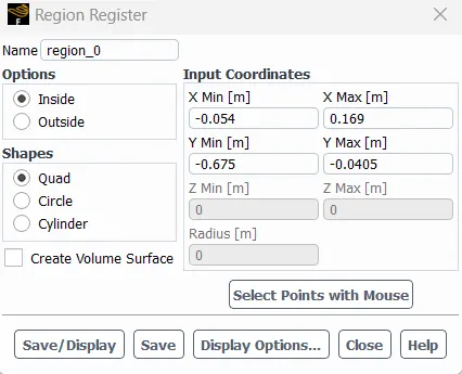
- Region is created in the model using coordinates at 20% and 30% immersion using region register, the coordinates for 20% & 30% immersion is calculated as follows :
The height of the gear box = 135 mm
20% of the height = 27 mm
30% of the heght = 40.5 mm
The y_max & y_min is found by viewing the coordinates at the specific height and intersectionof the gear box
20%
30%
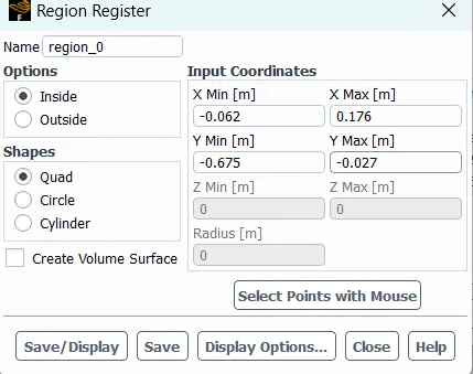
- Initialization - Hybrid
- After initialozation, the materials are patched in the appropriate regions
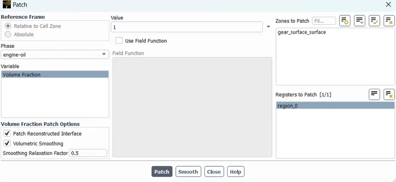
- The time step size = 0.0001 s
RESULTS
CASE-1 ( 20% immersion Engine-Oil)
Residuals
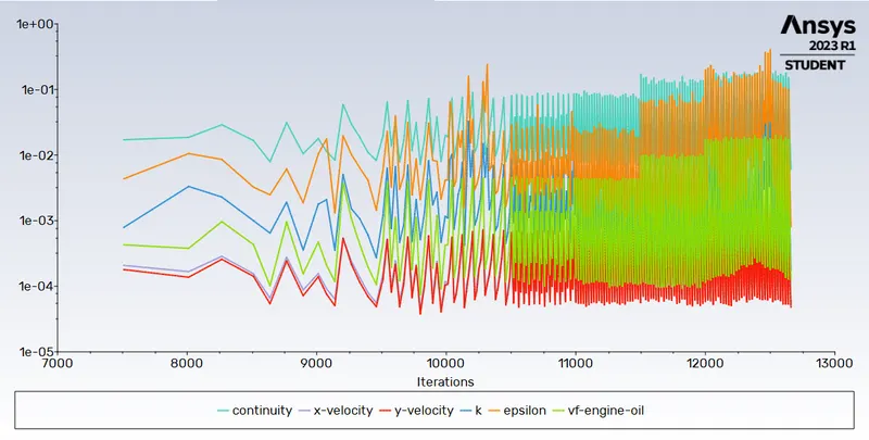
Flow Time

Link to Animation : Engine-Oil 20% Immersion Animation
CASE-2 ( 20% immersion n-heptane)
Residuals
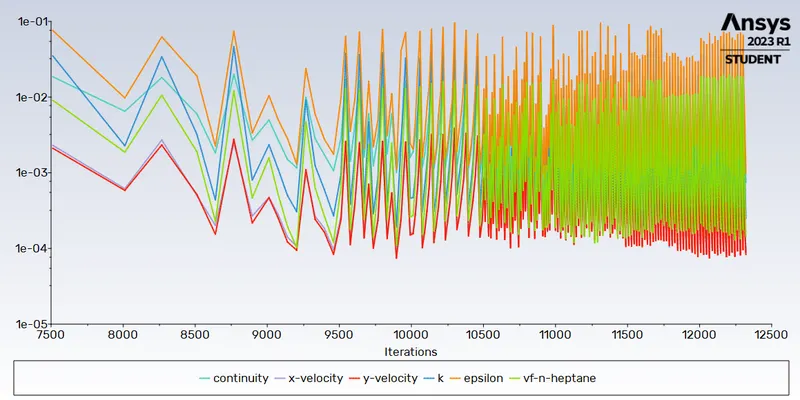
Flow Time

Link to Animation : n-heptane 20% Immersion Animation
CASE-3 ( 30% immersion Engine-Oil)
Residuals
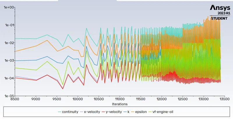
Link to Animation : Engine-Oil 30% Immersion Animation
CASE-4 ( 30% immersion n-heptane)
Residuals
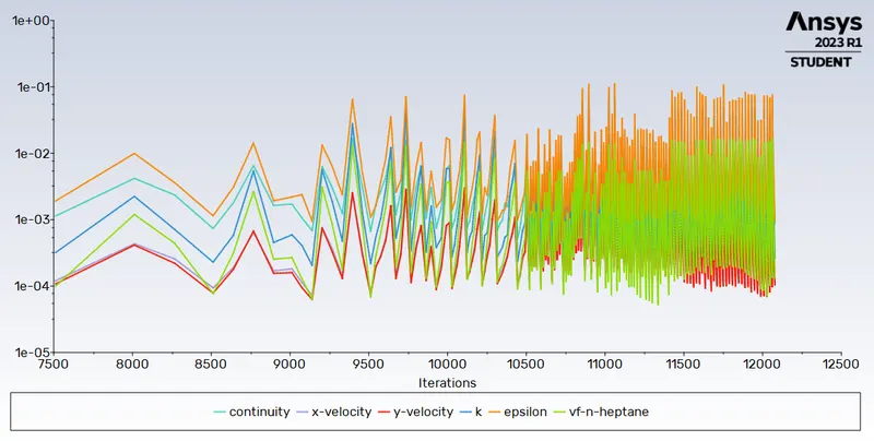
Flow Time

Link to Animation : n-heptane Immersion 30% Animation
OBSERVATIONS
- It can be observed that with increase in the immersion percentage, the lubricant is spread more evenly over the gear box teeth
- n-heptane can be seen having better results in terms of spreading due to low viscosity and density as compared to engine oil
- In this simulation, approximately two rotations of the gear box were studied to study the sloshing effect, due to restriction on computational power. Ideally, atleast 5 rotations must be studied to examine the effect in more detail.
PART-2
- What is Dynamic meshing? Give some other examples where dynamic meshing can be used.
Dynamic mesh is a mesh which changes shape to accomodate for the change in shape of the domain with time. It can be used to to simulate flap movement of airplane wing, two stroke and four stroke internal combustion engine, faling boxes in water tank etc
2. What is the fluid Sloshing effect? Discuss whether the sloshing effect is good or bad? Explain.
Fluid sloshing is a movement of free surface of a fluid due to relative motion with the container. It is caused by disturbance in the partially filled liquid container. Sloshing is essentially a type of fluid motion, it can sometimes be used as an advantage like here in the gear-box.In the gear-box sloshing helps in equally distributing the lubricant to all the teeth whereas in oil tankers, the sloshing of oil posses a disdavantage as the moving fluid can cause deformation in the container and supporting structure
3. What is the use of UDF?
A UDF is essentially a C programme or a C function that ANSYS FLUENT can dynamically load to augment its default features. it can be used for following applications
- Customize boundary conditions
- Material property definitions
- Adjust computed values on a once-per-iteration basis
- Enhance post-processing
- Enhance existing ANSYS FLUENT models (such as discrete phase model, multiphase mixture model, discrete ordinates radiation model)
4. Discuss the common errors that occurred in the simulation. A] 'Dynamic mesh failed' error. B] 'Negative cell volume detected' error.
The most frequent problems encountered while performing simulations with dynamic meshes are the dynamic mesh failed error and the negative cell volume detected error. One of these problems could first occur as a result of poor mesh quality. If the bulk of the cells in a mesh, whether it be unstructured or structured, are of low quality, calculation mistakes may ensue, crashing the simulation residuals. It's also a good idea to measure the smallest mesh cell's volume. A very slight border movement can cause the cell to collapse, resulting in this specific mistake.