Project 1 : CFD Meshing for Tesla Cyber Truck
Check and solve for geomtric errors in the model by using symmetry and assign appropriate PIDs. Perform meshing with different target length and given quality criteria.
Target Mesh Length
- Body = 3 mm
- Rims & Tyres = 2 mm
- Window = 3 mm
Form a wind tunnel and mesh it's surface
PROCEDURE
TOPOLOGY CLEANUP
- Import the Cybertruck model in ANSA
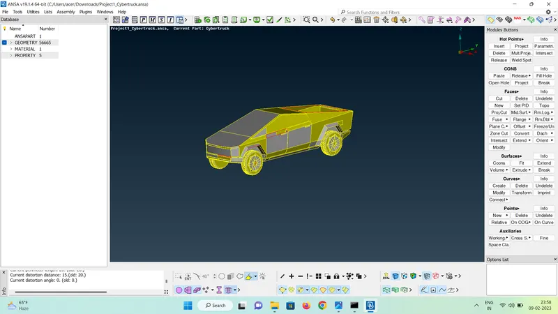
- Switch the view of the model in order to delete half part of the model. Sighting the symmetry in the model, it becomes easier to work on half model and then mirror it. This eases the topo cleanup process and saves time.
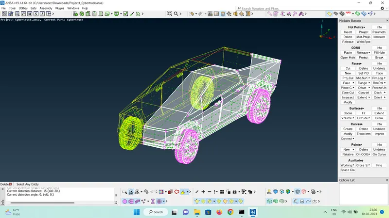
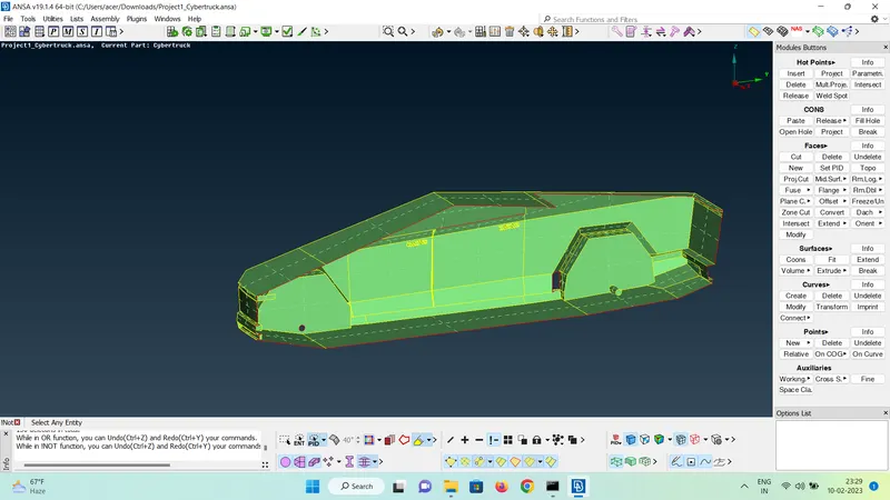
- The goal of topo cleanup is to achieve single volume for the body of the car and four different volumes for tyres. The wind tunnel simulation requires the volume between the car and the wind tunnel to analyze the flow over a car.
- To avoid forming different volumes inside the body, it is essential to perform topo cleanup and get rid of triple cons which can cause formation of seperate volumes, as triple cons may be the reason of formation of closed seperate volumes
- Boolean operations are used to isolate different components of the model to ease the process of cleanup
- The model cavity is cleaned to get a single volume inside and to capture the outer geometry of the model
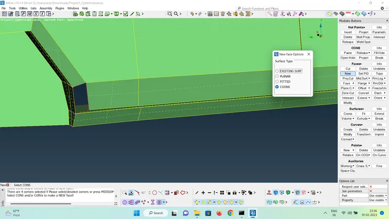
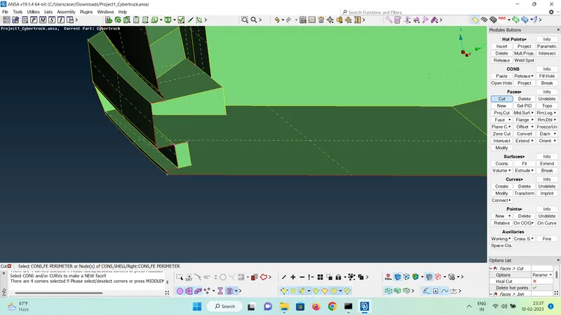
- Similar operations are implemented on the tyres, windows and the car body to get a single volume.
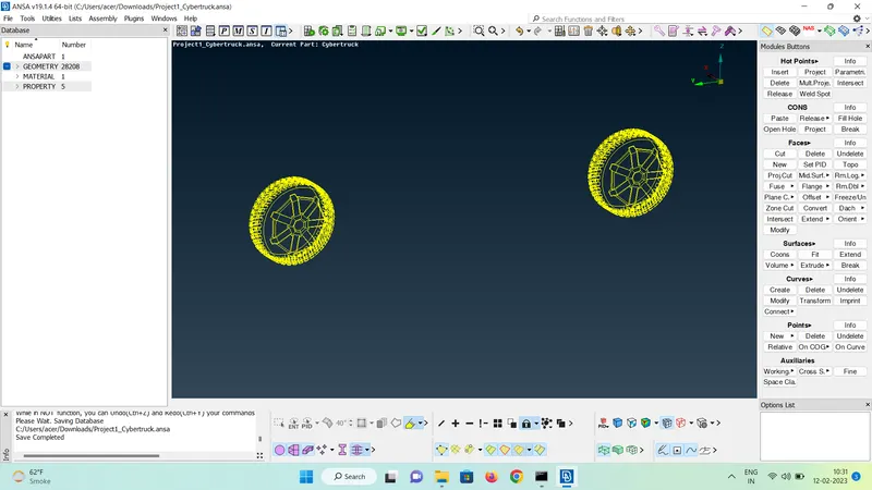
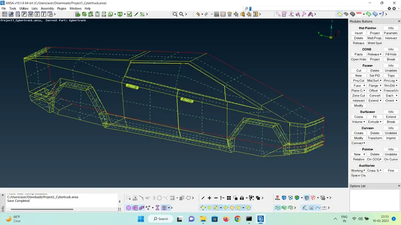
- Geometry checks are run on the whole model after the topo cleanup on the individual component level is done. This ensures proper cleanup of the geometry and is a necessary step
- The single cons that appeared in the geomerty cleanup are due to the cutting of the model in half. When we will mirror the model on to the other side, these single cons error will be resolved. So, apart from the single con errors, all the other errors are resolved using differnt options untill the geomerty has no errors.
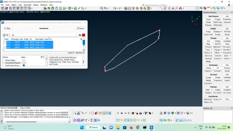
- The triple cons in the model must be resolved as it causes different volumes to be formed in the volume detection, and we need a single volume for the car body
PID ASSIGNING
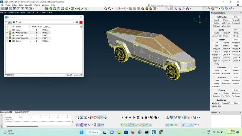
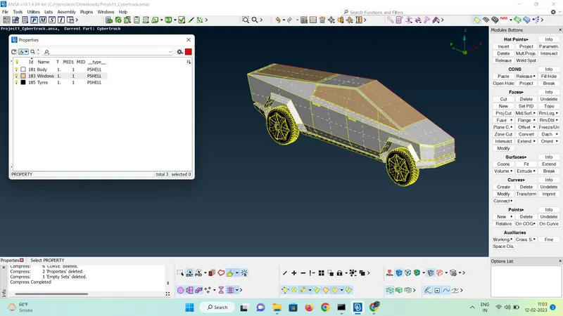
- The PID to the different components is assigned using the Properties Manager.
- New PIDs can be created by right clicking on the Properties Manager window and selecting New.
- The PIDs are assigned by clicking on the PID and then choosing Apply and then clicking on the component desired.
- After alloting PIDs to the components, many old PIDs become empty. To delete these, we need to use the Compress Option.
SURFACE MESH GENERATION
- Switch to surface mesh mode.
- The quality criteria is assigned for different PIDs.
- The goal is to attain a mesh with zero off elements, this ensures the quality of the mesh. Off elements are those elements which do not pass the quality criteria assigned.
- One-by-one all the PIDs are isolated and quality parameter is set according to the target mesh length mentioned in the objective above. The surface mesh element type is set as tria
- The quality Criteria are also set. Skewness, min angle trias, max angle trias are assigned by choosing the type of solver used. Here Fluent is chosen and the values are as follows
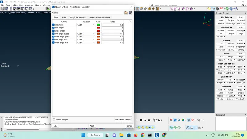
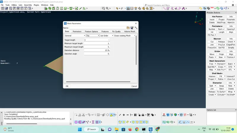
- The min length is according to the minimum dimensions of the PID. The PID is carefully examined for it's minimum length measurements by using the measure tool to make sure the mesh is appropriate and can capture the geometry well.
- Free > Visible is selected for the isolated PID. Here is an example for logo
- Length for Perimeters and macros is assigned
- After meshing the surface, the mode is changed from shadow to hidden, which shows the off elements which are existing in the designated colours
- To get a better mesh, Reconstruct > Visible option is used.
- To solve these off elements, options like Move, Smooth, Reconstruct, Improve, Split are used, until no off elements are left.
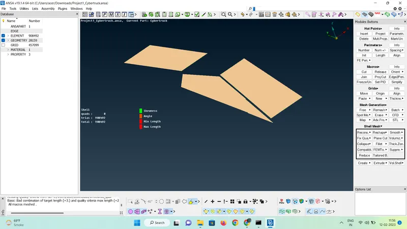
- Similarly all the other PIDs are meshed and the off elements are solved
TYRES
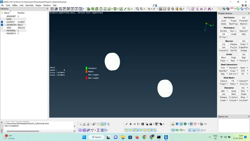
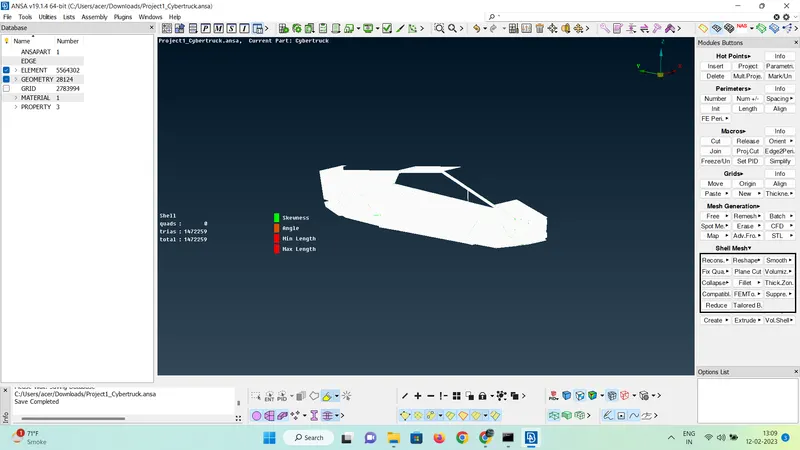
BODY
- Meshing the body needs to be done by only selecting the perimeters in the length option and deselecting the ones which are adjacent to the other PIDs, so that the different mesh length of the different PIDs will not make the mesh achieved on the PIDs to vanish
MIRRORING OPERATION
- After completing the mesh of the model, we need to mirror this half to the other side and make a complete model.
- This operation will mirror the components as well as the mesh elements to the other side.
- We use the copy option in transform
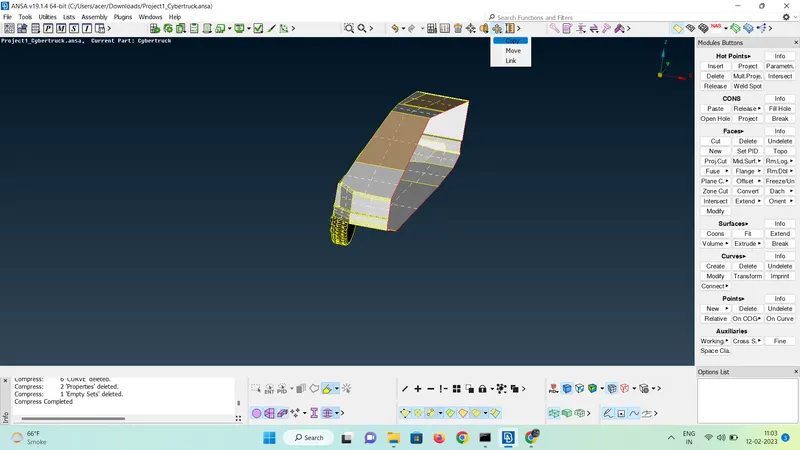
- The symmetry option is selected and the plane is selected by mirror 3-points plane option.
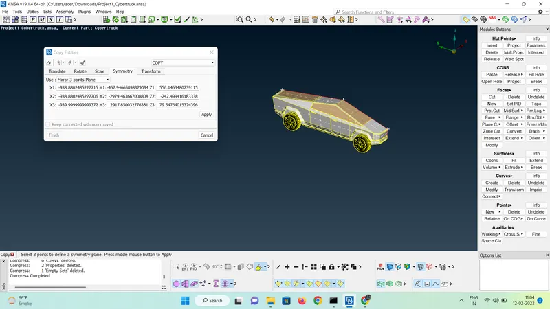
- Three points are selected to get a desired plane.
- In tranformation options, the PID is not to be given any offset and the settings are kept at default.
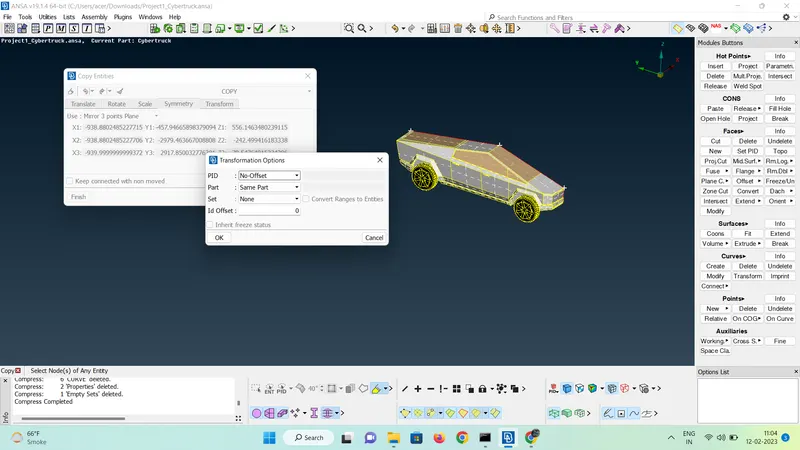
- Press finish to mirror the model.
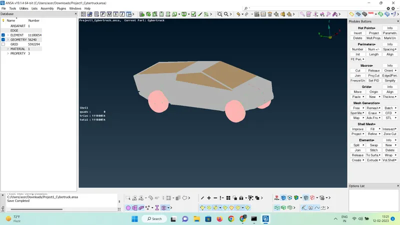
- Check the single cons present in the model and resolve them using paste option.
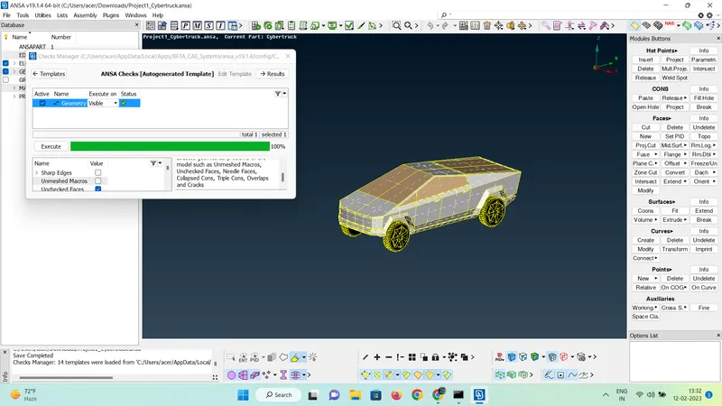
- Perform geometry checks on the model to ensure a single and triple cons free result.
CREATING WIND TUNNEL
- Wind tunnel is created to perform CFD simulation on the aerodynamics of the car
- Wind tunnel is created by introducing points in the required locations by using the relative option and creating a surface using curves and new option
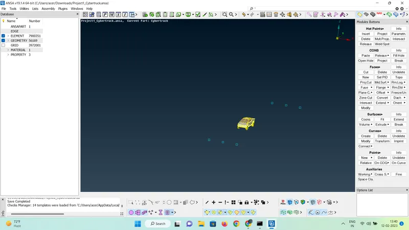
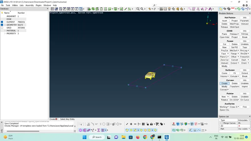
- The size of the wind tunnel is calculated such that it has a distance of 2 times the length of the car from the front, 4 time the length of the car from the rear, 3 times the length of the car from the top and some small amount below the tyres. To achieve this size, relative option is used accordingly.
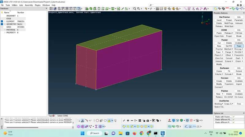
- Offset option is used to create a surface on top of the car, using the first surface created
- After using the offset option, new surfaces for sides, front and rear are created and PIDs are assigned to them
MESHING WIND TUNNEL
- To mesh the wind tunnel, the bottom is kept at 20 mm target length and the top at 100 mm target length with appropriate quality criterias as the flow near the car is important
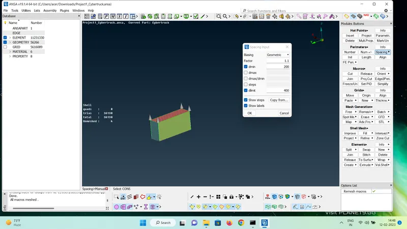
- The front and rear faces are provided with a transition from 20 mm to 100 mm ( from bottom to top ) using the spacing option. The progression is set as geometric. This ensures a smooth transition and strategically placinf finer elements only where they are needed for accuracy. Side faces are also meshed. This meshing does not need any quality criteria as the transition is defined here
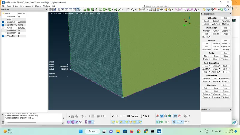
VOLUME GENERATION
- Switch to the volumetric mesh mode
- Select Define > Autodetect > Wholedb
- 6 volumes are detected by ANSA, out of which only the volume between the car and the wind tunnel is kept and the volumes of car body and tyres are deleted
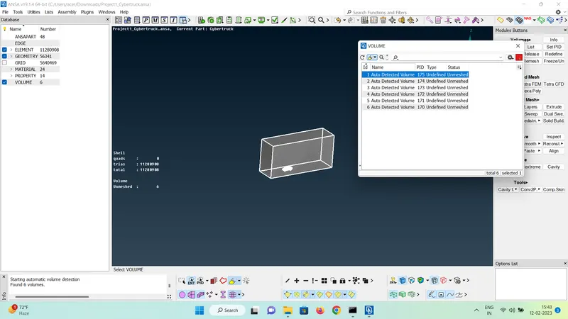
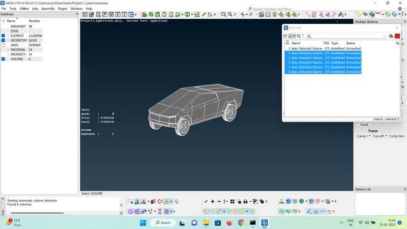
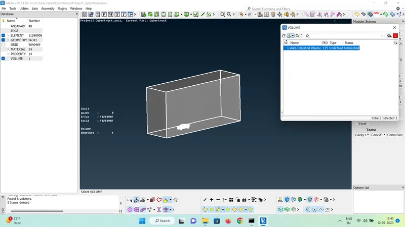
- Further we have to mesh this volume using tetra mesh elements
RESULTS
- The volume between the car and the wind tunnel is achieved to perform analysis in order to study the aerodynamics of the car.
LEARNINGS AND OUTCOMES
- Using symmetry to make the meshing and topo clenaup easy.
- Transform option to mirror a model.
- Isolating different components in order to make the topo cleanup and meshing easy to handle.
- Using Cons2Curve option to trace a geometry.
- Concept of off elements.
- Calculation of wind tunnel size.
- Determination of quality criteria by measuring the smallest possible lengths in the component in order to decide the minimum length
- Skewness, minimum length, maximum length, angle trias
- Tools like move, reconstruct, improve, split, paste to solve the off elements in the model.
- Offset and relative options
- Importance of creating a single volume inside a car model
- Spacing and transitional mesh
Link : Cybertruck Meshed Model