Week 3 Challenge : CFD meshing on Turbocharger
OBJECTIVE
For the given model check for geometrical errors and form appropriate volumes with mesh element type tria and target mesh length of PIDs as follows
- Blade stage-1 = 1 mm
- Blade stage-2 = 1 mm
- Impeller = 2 mm
- Shaft rotor = 1 mm
- Turbo casing = 5 mm
- Compressor casing = 5 mm
- Inlet casing cover = 5 mm
PROCEDURE
TOPOLOGY CLEANUP
- Open the model of turbocharger in the ANSA software
- The raw model can be seen having several glitchings which indicates overlapped surfaces and several single cons of extra surfaces, it also consists of holes in the geometry which need to be patched for th formation of appropriate volumes. Firstly, a geometry check is performed to analyze the faults and there location. Single cons need to be removed whereas triple cons are checked for validity and purpose in the model.
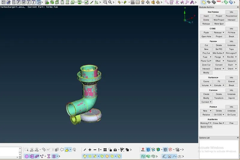
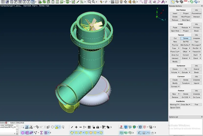
- To clean the overlapped surfaces the PID designated to the overlapped surfaces is isolated and then the delete tool is used to delete the surfaces
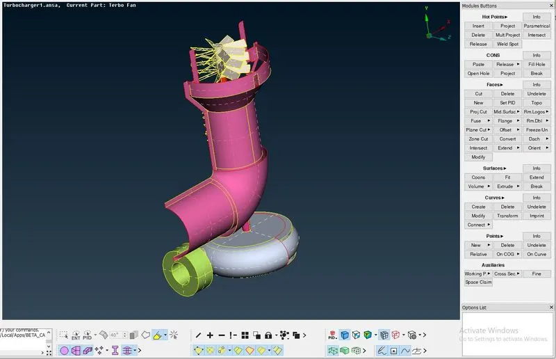
- After eliminating the overlapped surafaces, the extended surfaces are removed and the surfaces with holes are patched by coons and fill hole options
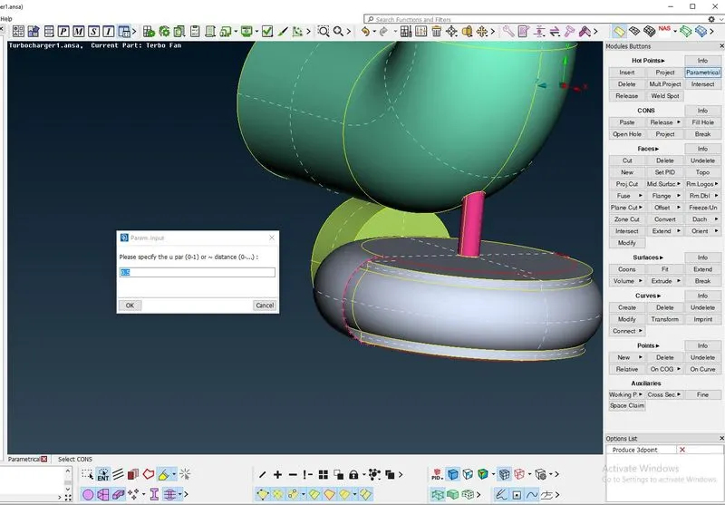
- The curved surfaces are patched by inserting hot points using the parametric options and creating smaller surfaces to patch the curved surface
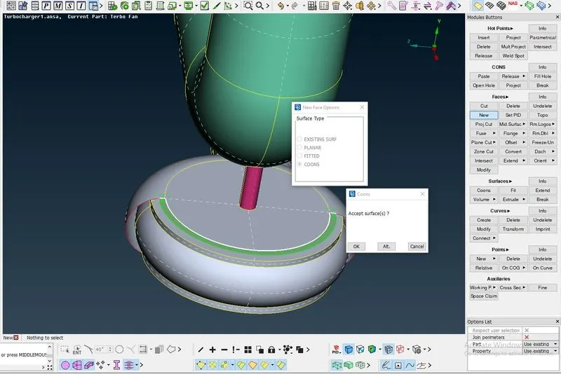
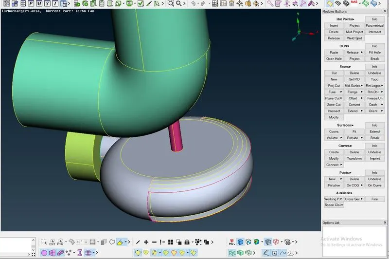
- The intersecting surfaces are also corrected by using the intersect tool and deleting the extended surfaces formed
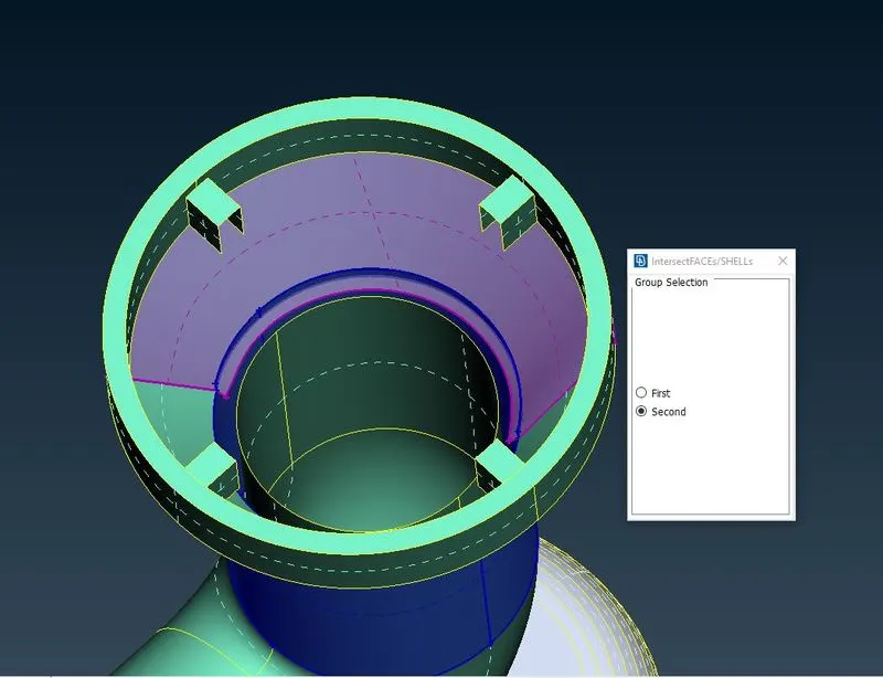
- As the aim of the topo cleanup is to create appropriate volumes, only whole volumes must be formed. For this purpose the shaft is also cleaned to remove overlapped surfaces and the inner faces are deleted.
- To remove the face on the impeller cut tool is used
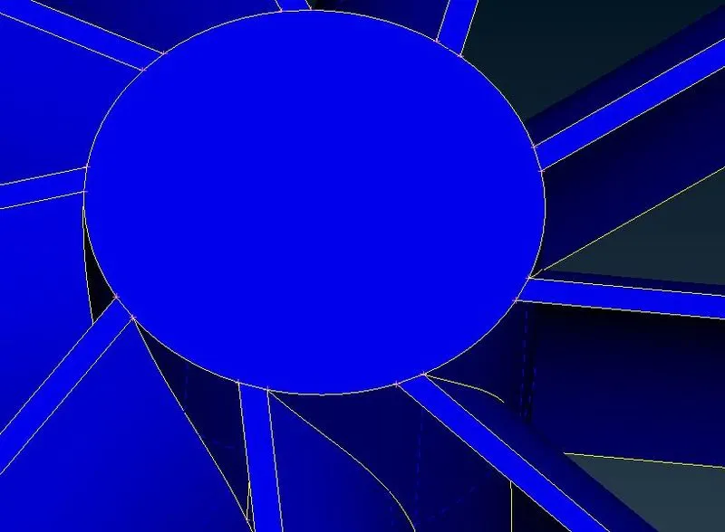
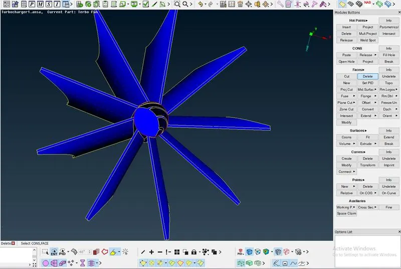
- Topo is used to remove all the single cons in the shaft
- Glitches in the shaft can be removed by projecting the cons of the blades on the shaft and using cut tool to remove overlapped surfaces
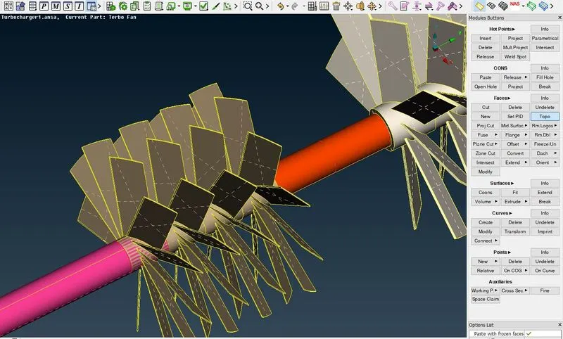
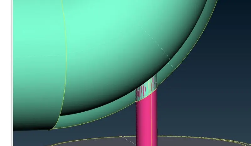
- By performing geometry check on the model, it is checked if there are no single cons and unnecessary triple cons.Triple cons shown in the figure are required in the model so they are kept
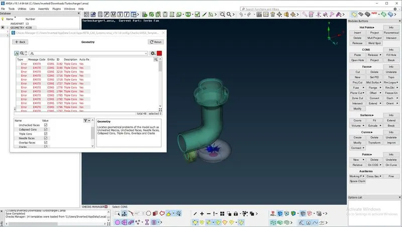
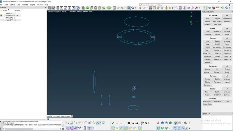
- The aim is to form single volume for the shaft so that it can be deleted later
PID ALLOCATION & GEOMETRY CLOSING
- Geometry is closed to form appropriate volumes for CFD analysis
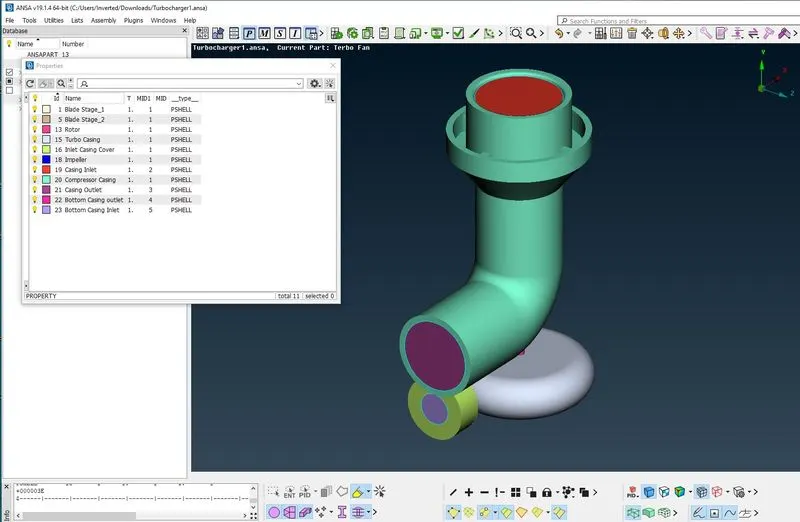
- Appropriate PID is allocated to each and every component
Surface Meshing
- After changing to surface mesh mode. Each component surface is meshed using Free Mesh < Visible, after isolating the components using show only
- For meshing each and every component with different target length. Each time the mesh parameters and mesh quality criteria must be checked and then by using length option, perimeters and macros of the component is set
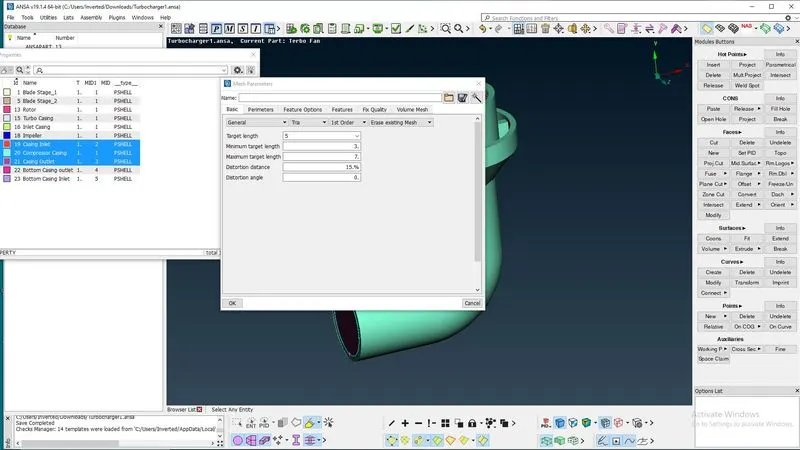
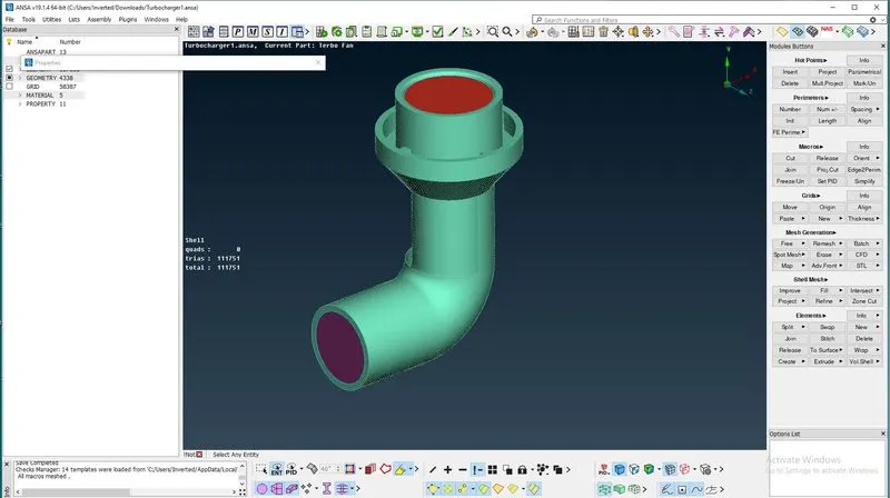
- Due to the different mesh length on impeller and shaft, the meshing on the shaft disappears after meshing the impeller. To resolve this issue, the shaft is meshed again by setting the default range of macros from (1-2). Due to this, we get a transition of mesh elements from impeller to shaft
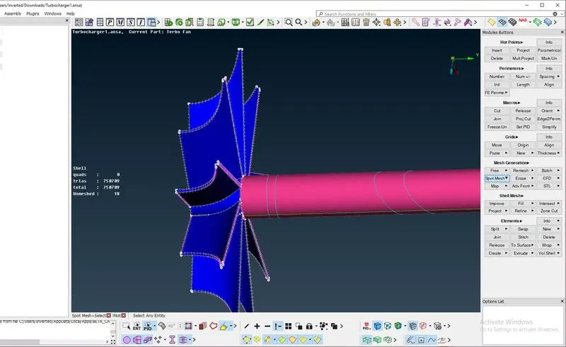
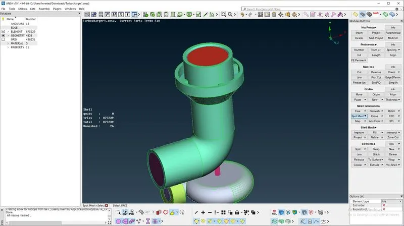
- Similarly, the mesh at the compressor casing and turbo casing is dealt
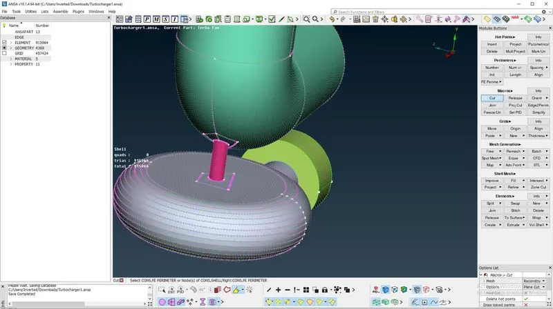
- Cuts are made at the transition points to facilitate the transition area
Volumetric Mesh
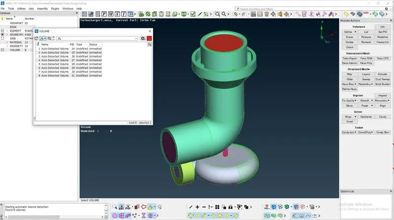
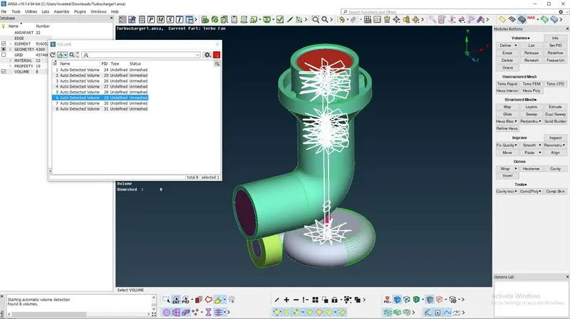
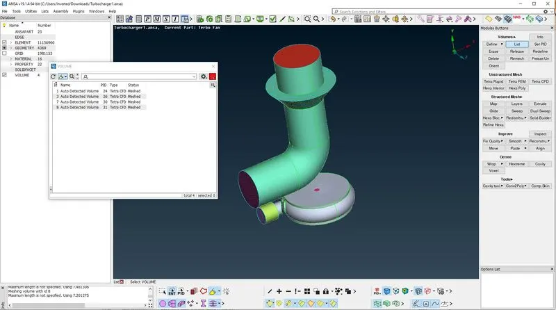
- After switching to volumetric mesh mode, by using the define option, volumes are autodetected from the whole database
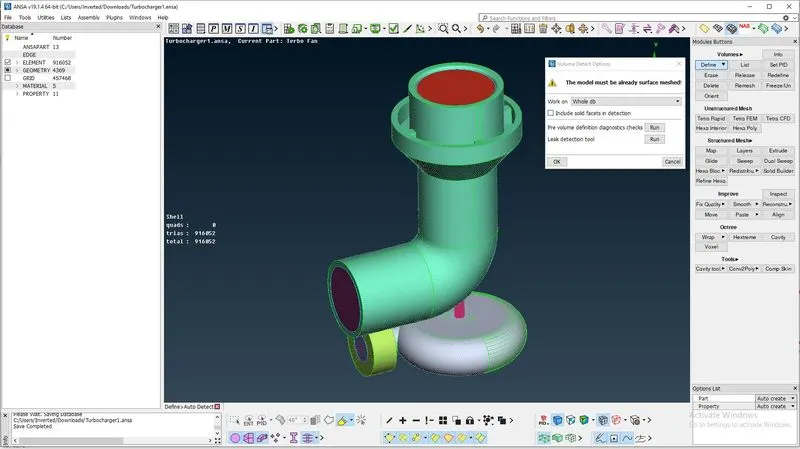
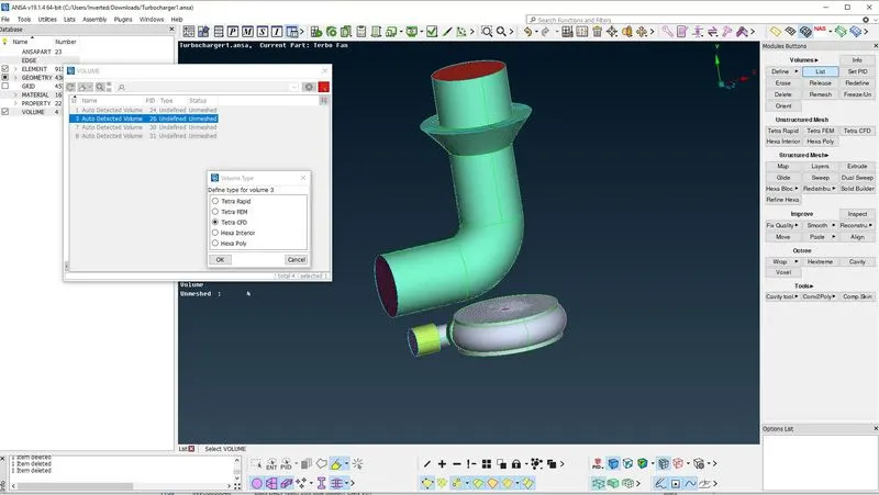
- From the detected eight volumes, the volumes corresponding to the thickness of the model and the shaft are deleted in order to get the volume through which fluid will flow to proceed with CFD analysis
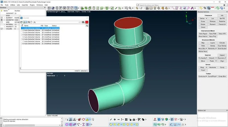
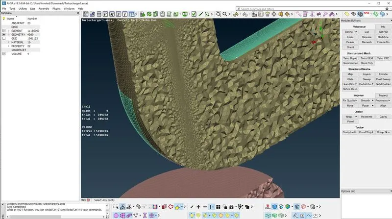
- The remaining volumes are meshed using the Tetra CFD Mesh option obtained through Remesh
RESULTS
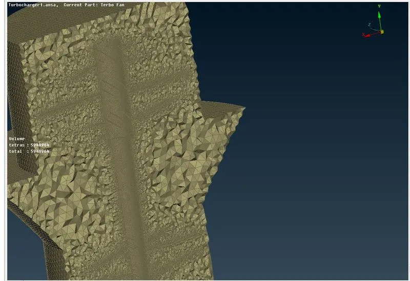
- The mesh obtained by volumetric meshing can be seen by cutting the volumes in half
- We get the meshed volumes in tetra element type as follows
OBSERVATIONS
- Surface mesh at the transition of components with different mesh length is in a specific range
- The mesh is observed to be finer at the blade and shaft areas to capture the geometry of the cavity formed by the blades and the shaft efficiently
LEARNINGS
- New tools for topo cleanup like intersect, project in cons, fine etc.
- Formation of surfaces using multiple hot points to capture the geometry better and obtain smooth surfaces
- Meshing the components with different target mesh length and achieve the mesh size transition from one component to another
- Generate volumetric mesh of the model and selecting volumes through which the fluid will flow
The meshed model attached in the link below: