Week 7 - Creating connection for Rear door
PROJECT REPORT
AIM:
1. Create and apply distinct PIDs for various components within the Rear door FE model.
2. Establish appropriate connections between the components within the model to ensure functional coherence.
OBJECTIVES:
1. Create distinct PIDs for various components within the Rear door FE model.
2. Apply distinct PIDs for various components within the Rear door FE model.
3. Perform suitable connections within the Rear door FE model.
PROCEDURE:
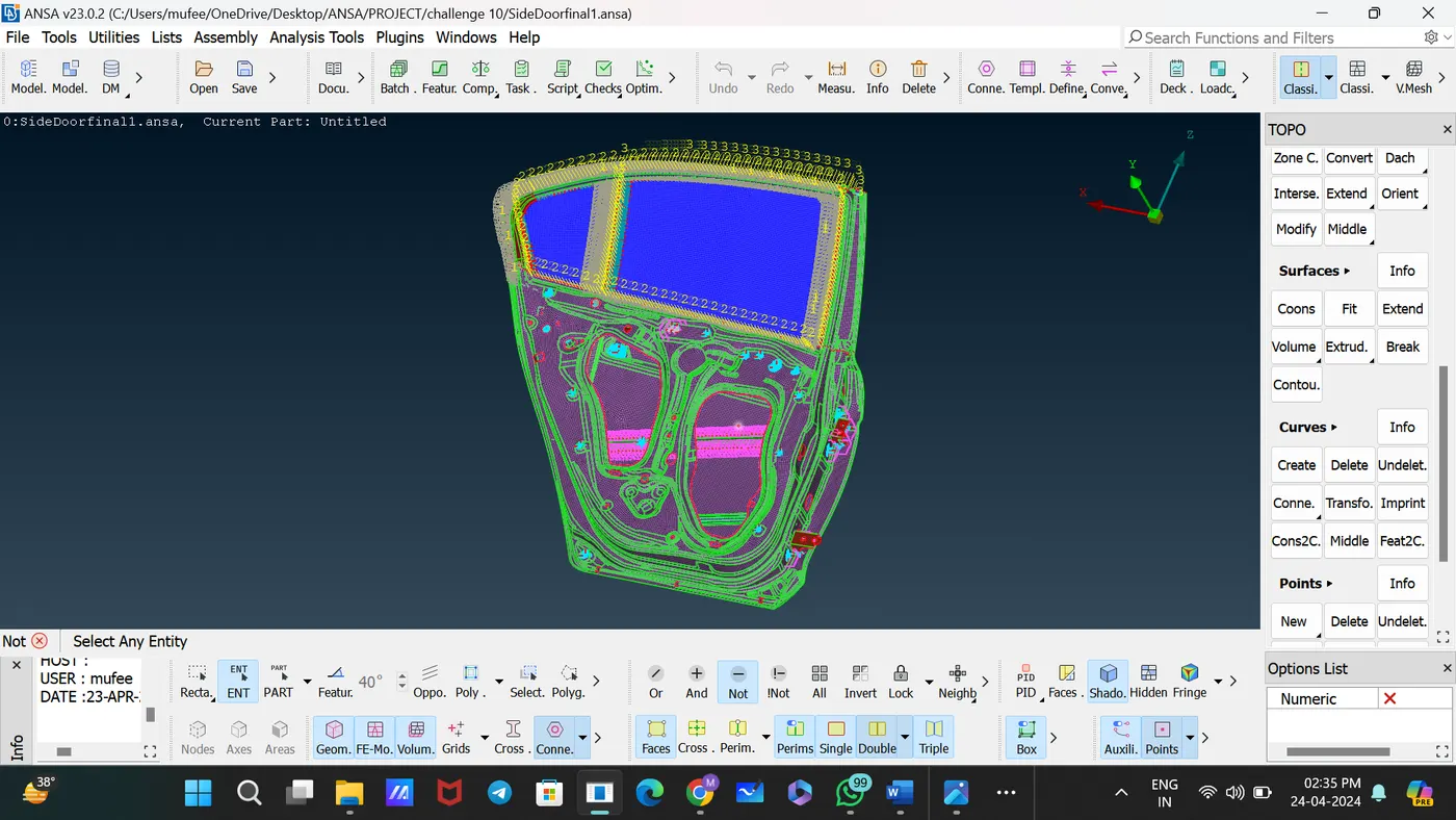
This is the FEA Model given in the Challenge.
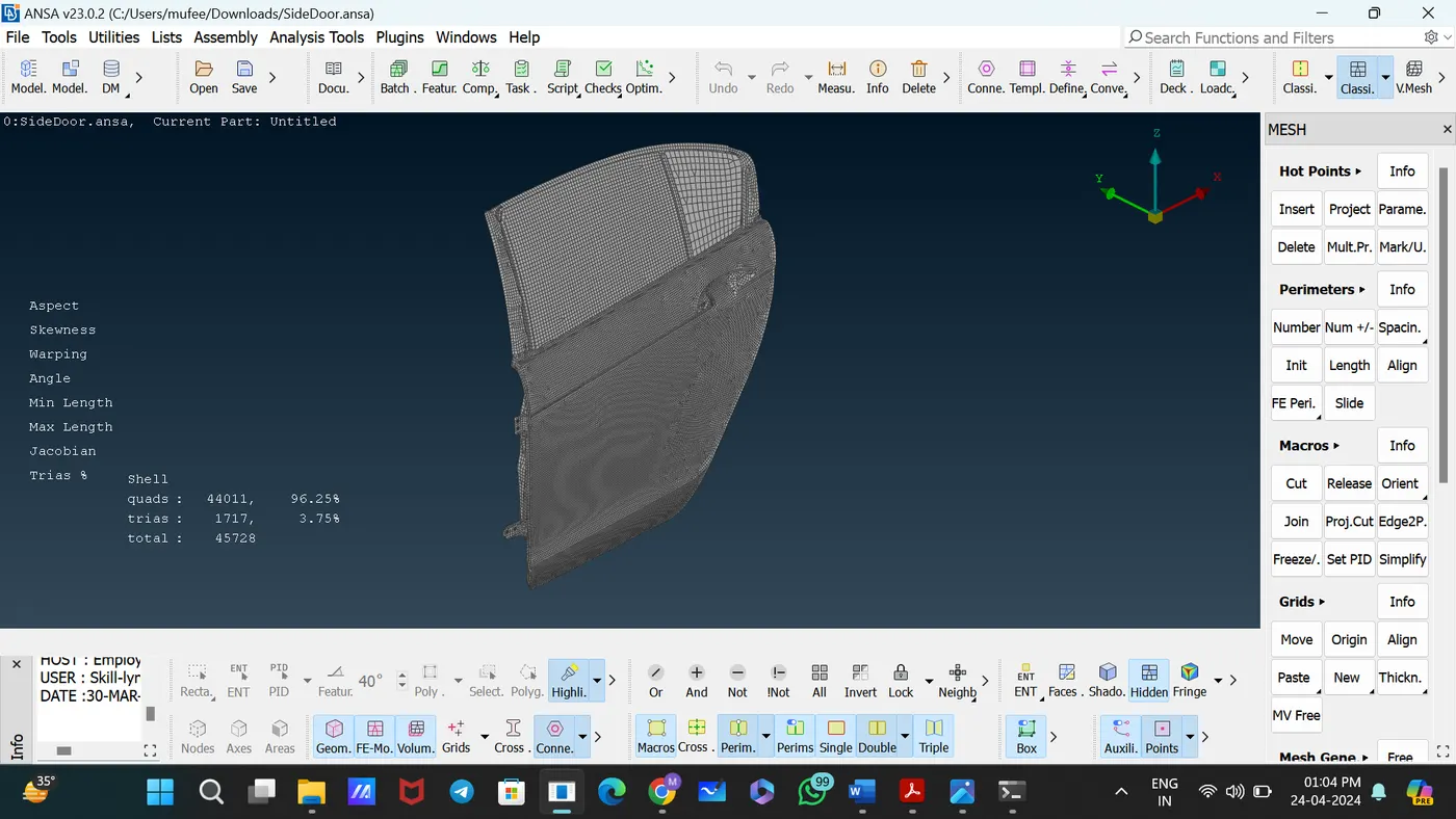
Set the PID for each component using the command [Faces – Set PID]
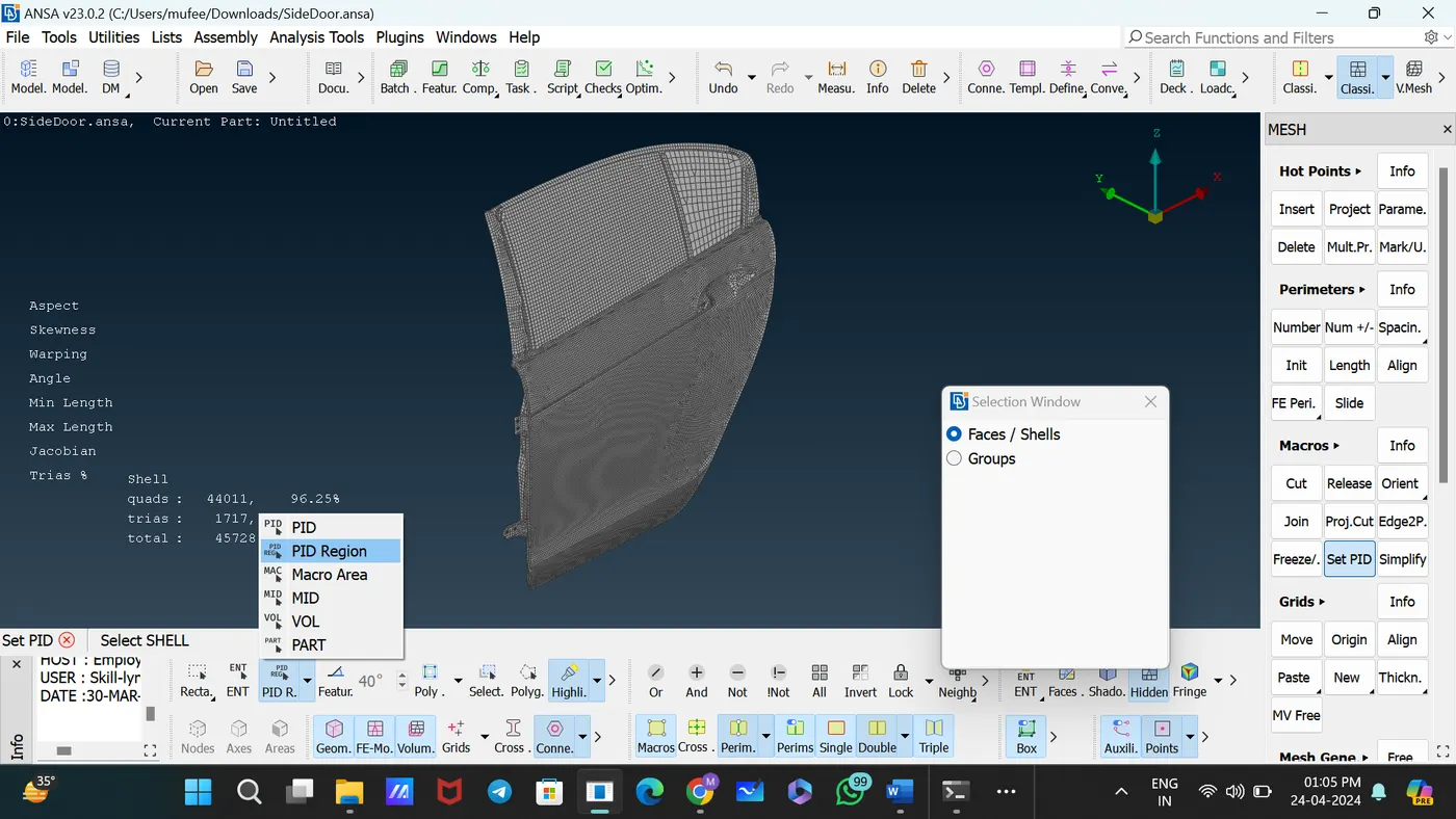
Select the component as PID Region.
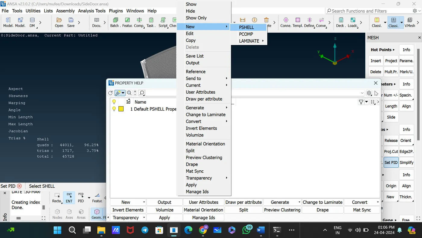
Create a new PSHELL and set PID for that component.
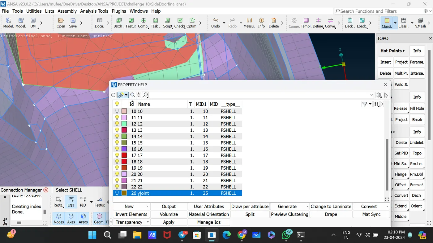
Completed the process of setting PID for components by following the above steps.
1. Bolt connection
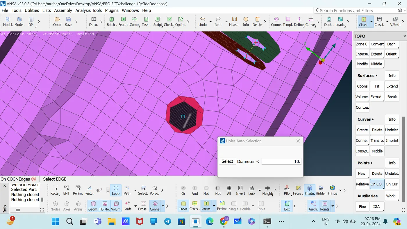
Create3D points on center of gravity [Topo—Points—On COG]
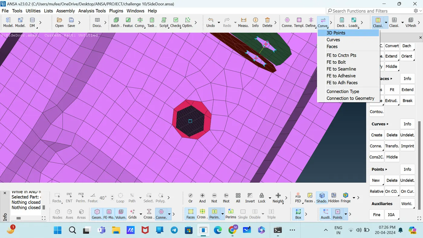
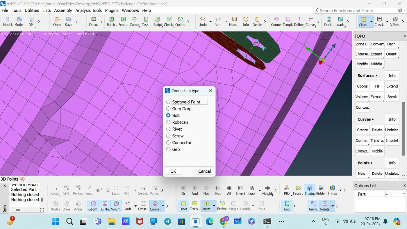
Covert the 3D points to Bolt [Convert—3D points—Bolt]
Open the connection manager and select the bolt.
Set the FE Representative Type as BOLT.
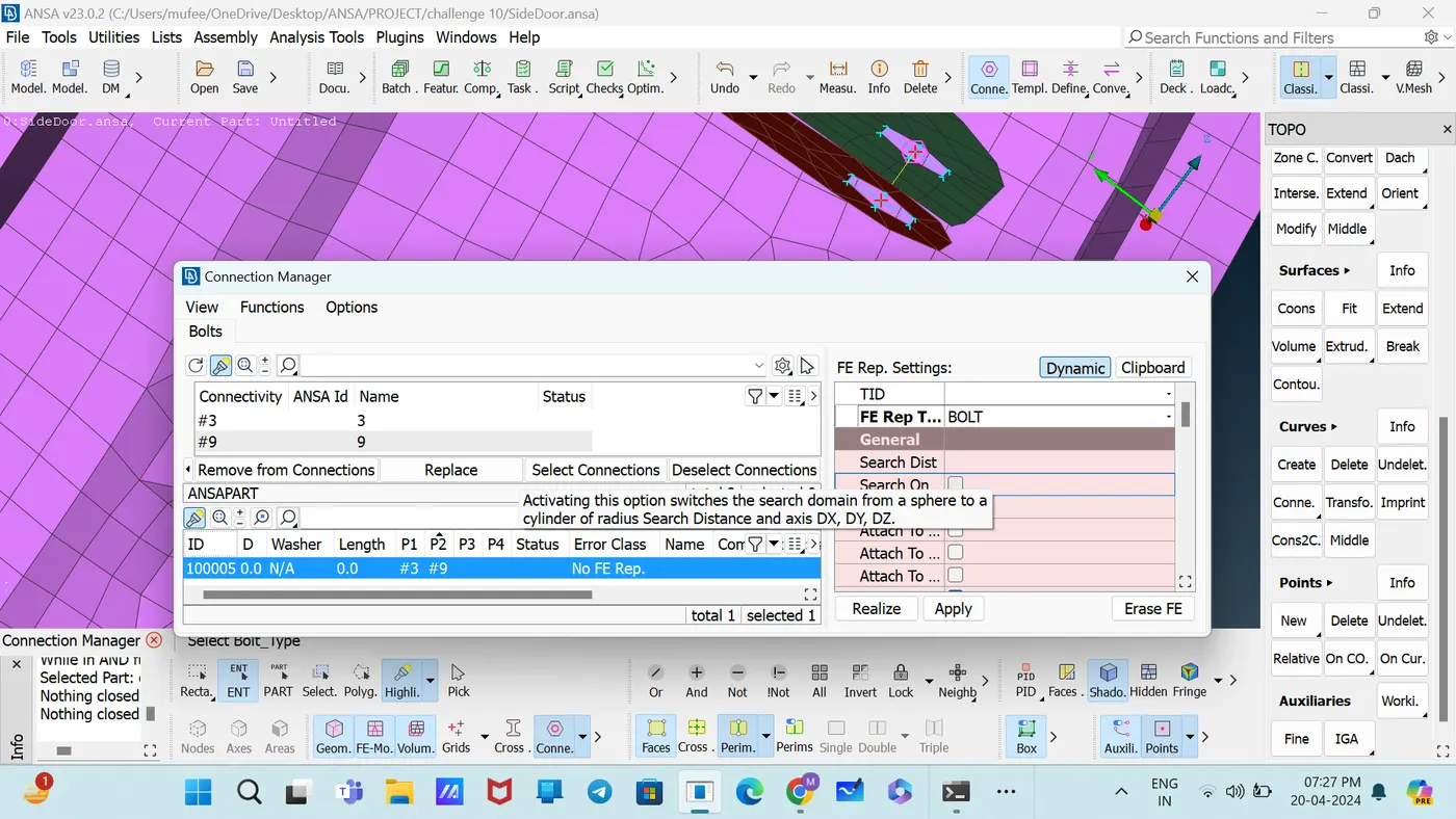
Select the P1 and P2 and Apply, Realize.
2. Nut and Bolt (RBE2)
Use the command in DECKS—NASTRAN [ELEMENTs—RBE2]
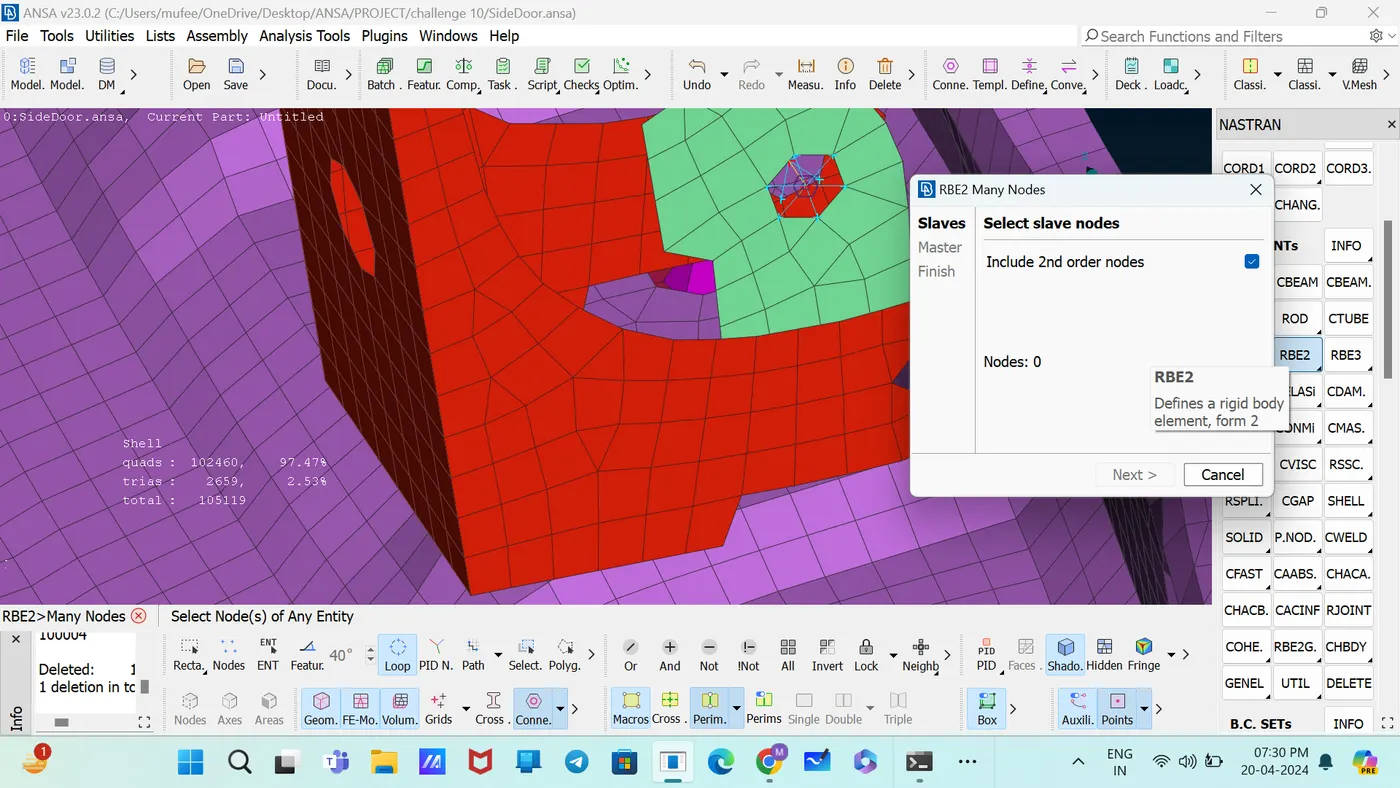
Select the slave and master nodes using the loop selection method.
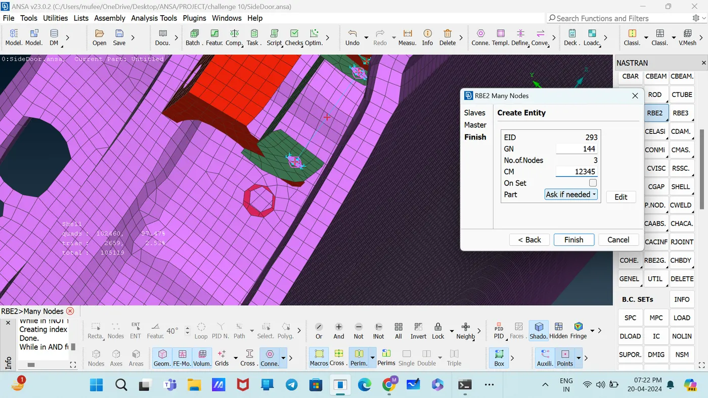
Set the Degrees of Freedom and Part.
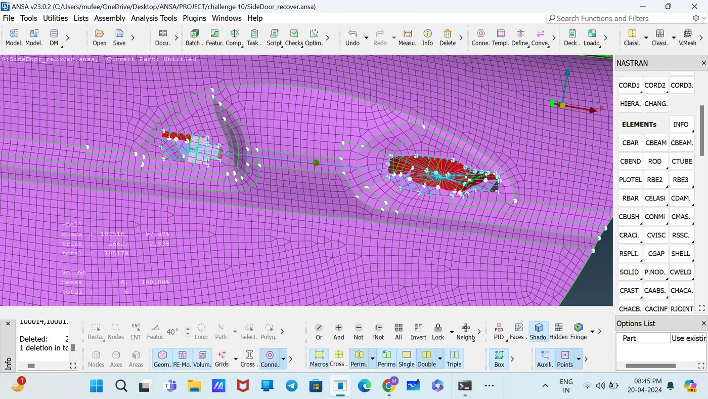
For the door handle, use RBE2 --2 nodes and connect like this and provide the mass using the command DECKS—NASTRAN [ELEMENTs—CONMi].
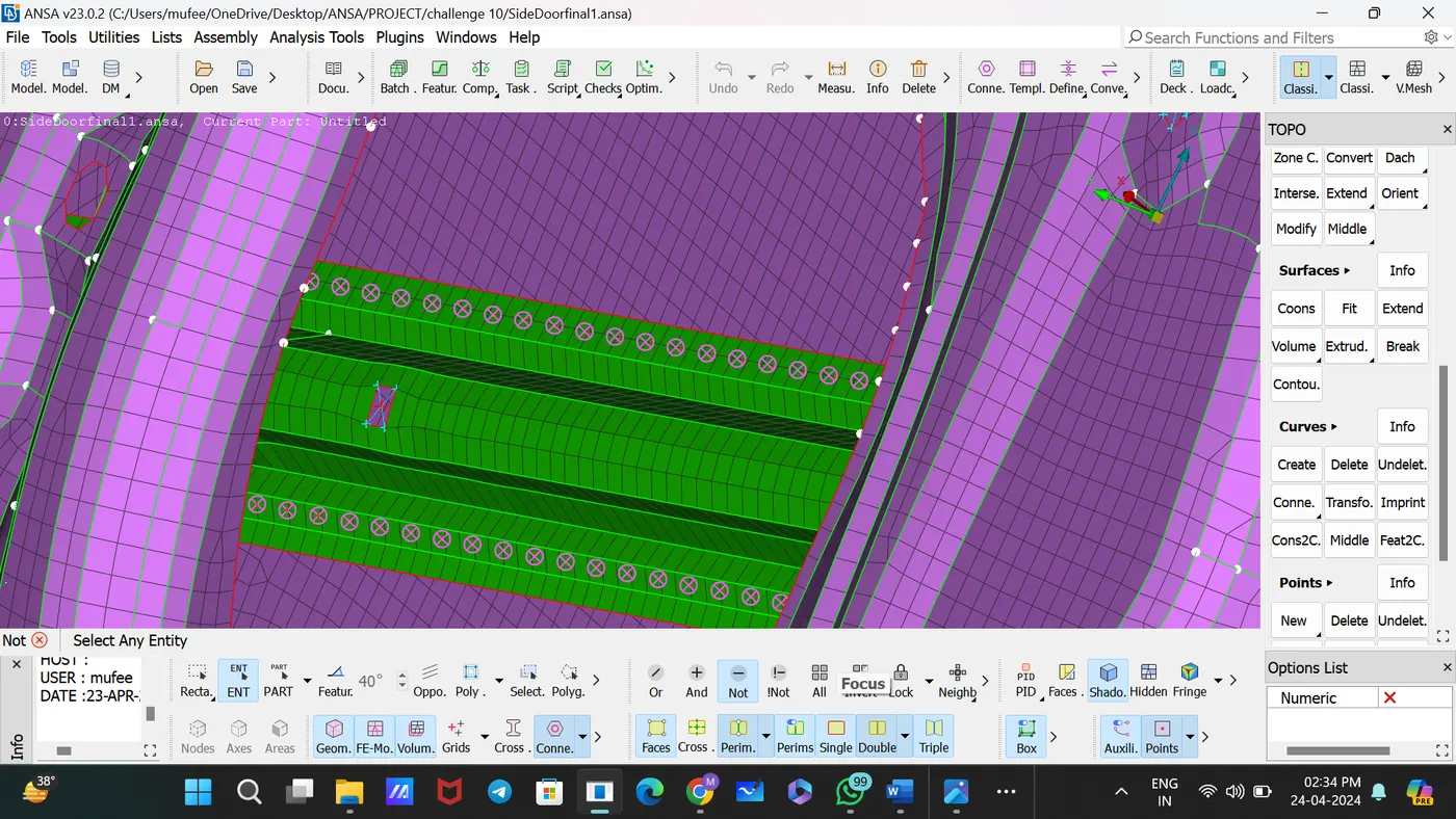
3. Spot Weld
Create3D points on center of gravity [Topo—Points—On COG]
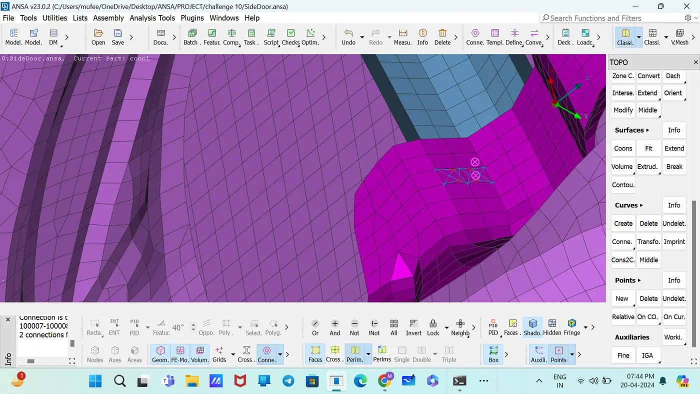
Covert the 3D points to Spot Weld Points [Convert—3D points—Spot Weld Point].
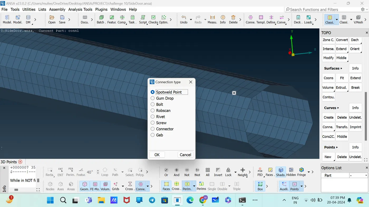
Open the connection manager and select the Spot weld points.
Set the FE Representative Type as RBE3-HEXA-RBE3.
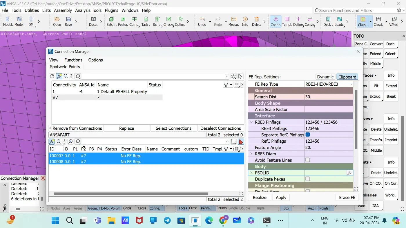
Select the P1 and P2 and Apply, Realize.
Determine the PID for Weld material.
Set the Degrees of Freedom and Part.
4. CBUSH
Create the curve of the perimeter of the mirror using the command [Topo—curves—Feat2Curve]
Convert the curve to spot line [convert—curve—spot line]
Open the connection manage and select spot line.
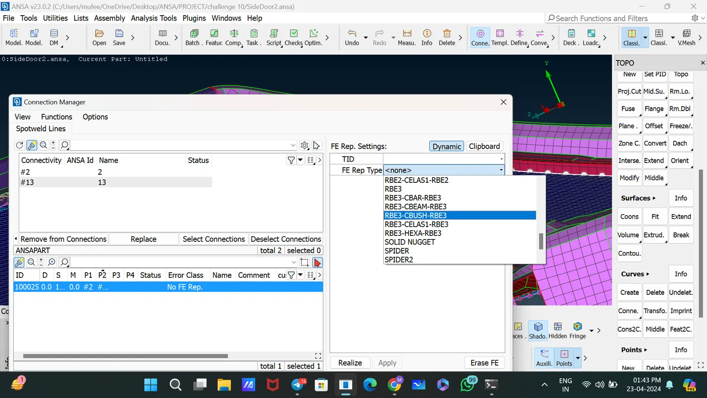
Set the FE Representative Type as RBE3-CBUS-RBE3.
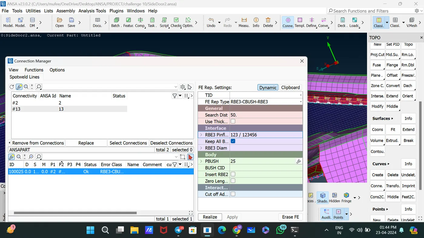
Set the PBUSH property like stiffness.
Tick the Keep all Branches.
Prove the value for s, gap Search distance.
Select the P1 and P2 and Apply, Realize.
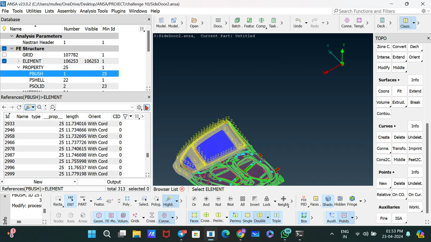
For changing the coordinates from local to global,
Database – PBUSH—References—Select all—modify—orientation to with cord and CID is 0.
5. DYNA spot Weld:
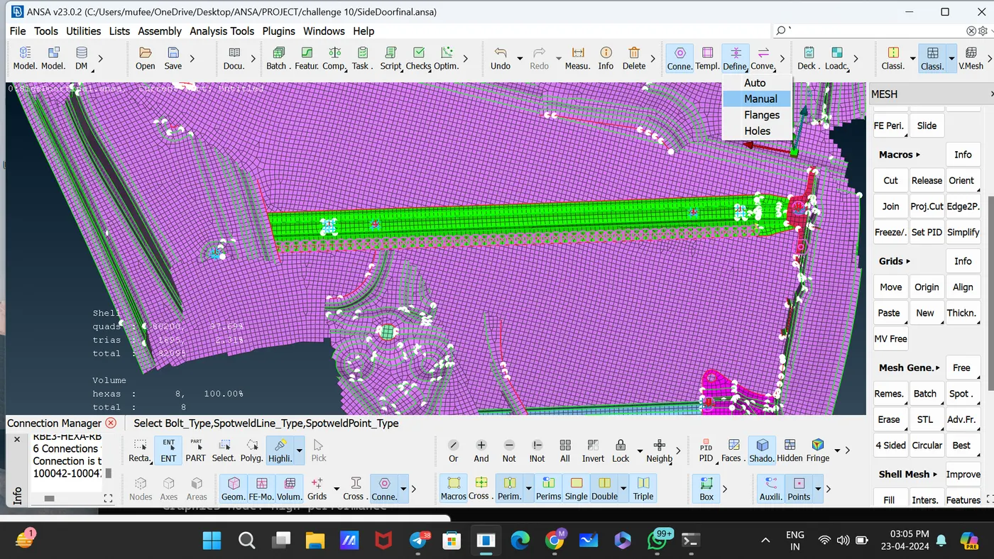
Define the spot weld points using the command [Define—manual]
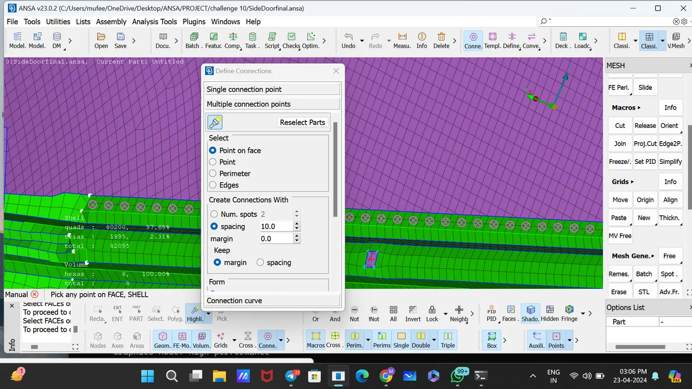
Select the PID and distance between the adjacent spot points.
Open the connection manager and select the Spot weld points.
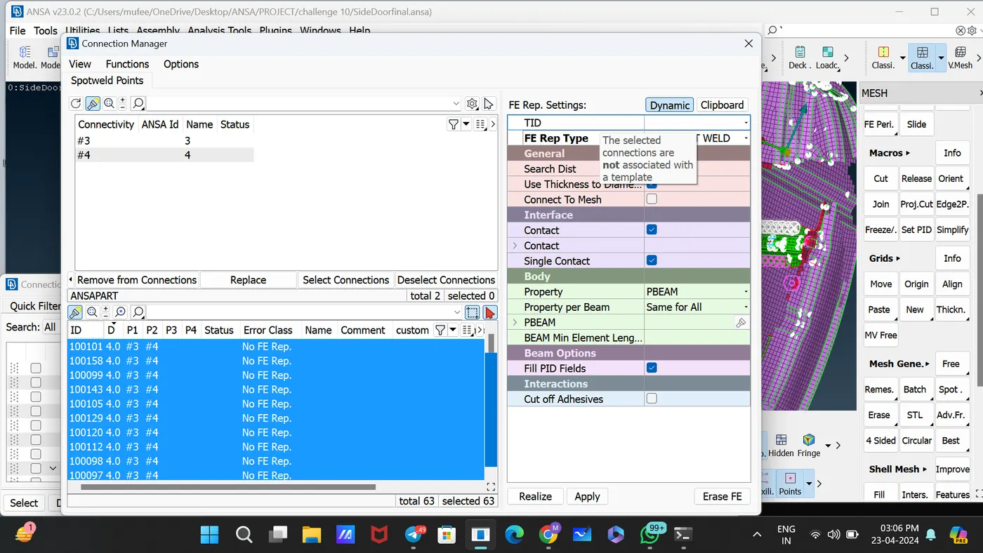
Set the FE Representative Type as DYNA spot weld.
Prove the value for D, Search distance.
Select the P1 and P2 and Apply, Realize.
CONCLUSION:
by creating and applying distinct PIDs for various components and establishing suitable connections within the Rear door FE model, we have enhanced its functionality and coherence. This systematic approach ensures precise modeling and facilitates comprehensive analysis, contributing to the optimization of rear door design and performance.