Week 7 - Creating connection for Rear door
AIM
- To set PID and perform connections for the given rear door model with different connection techniques using ANSA.
PROCEDURE
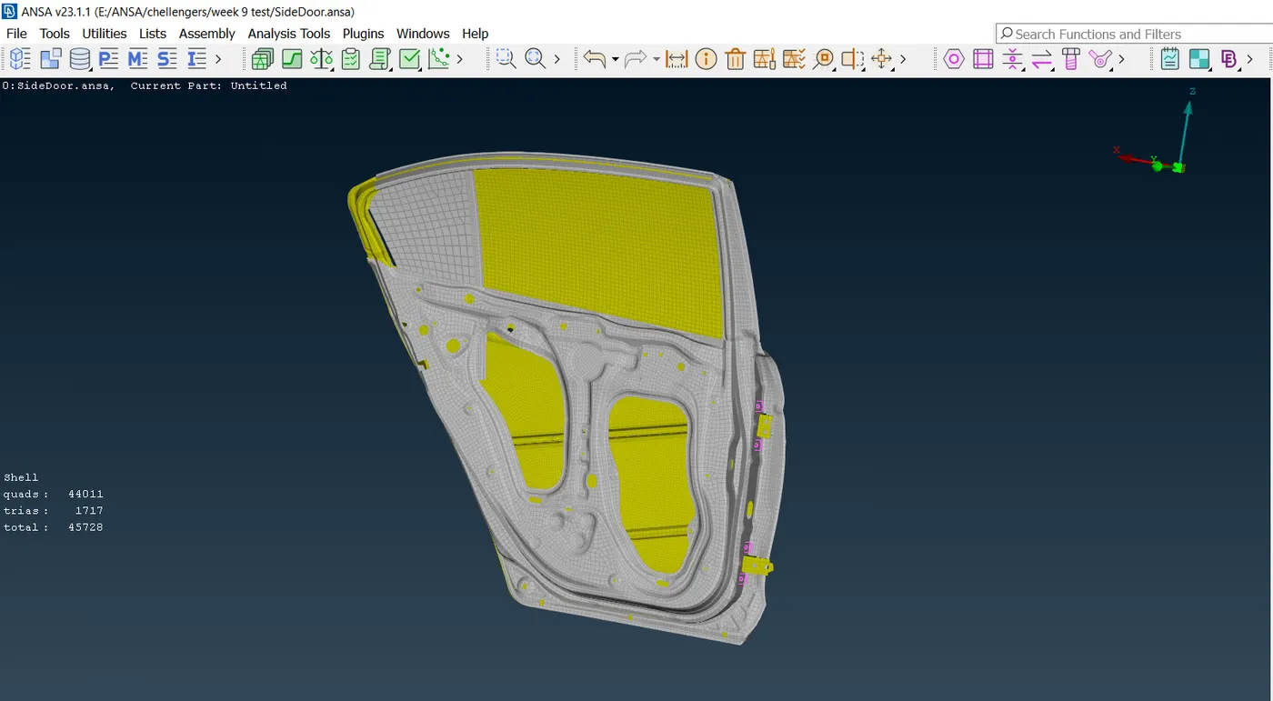
- The given model is imported into the ANSA software. It is observed that a default PID is set for the model. The imported model is shown in the figure below.
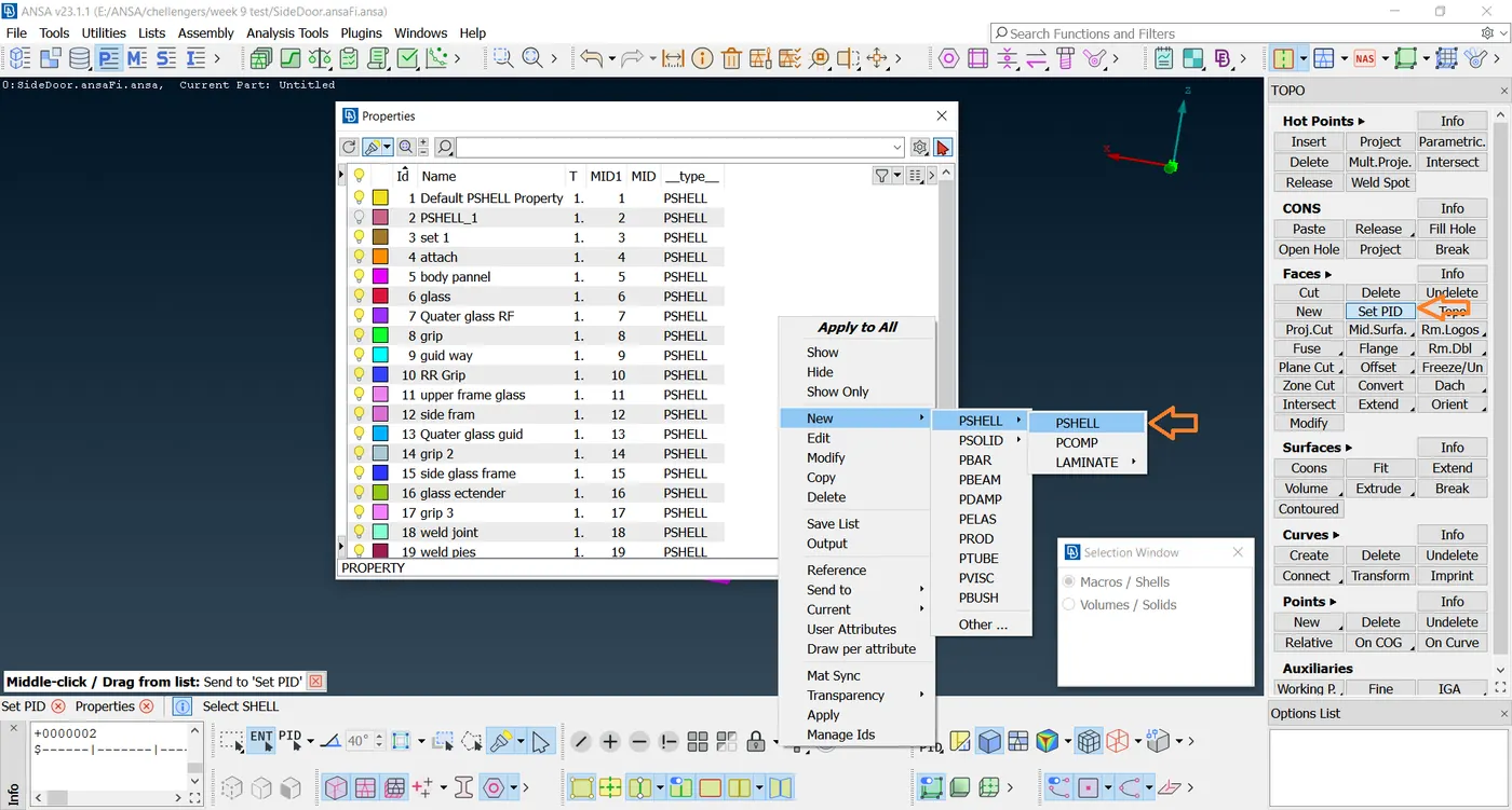
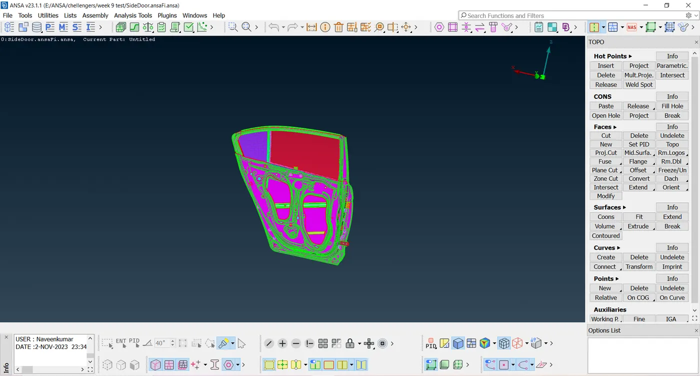
- Now go to Mesh-Macros-Set PID select the desired part using the boolean operations and create the New-PSHELL property for the selected component. The set PIDs are shown below.
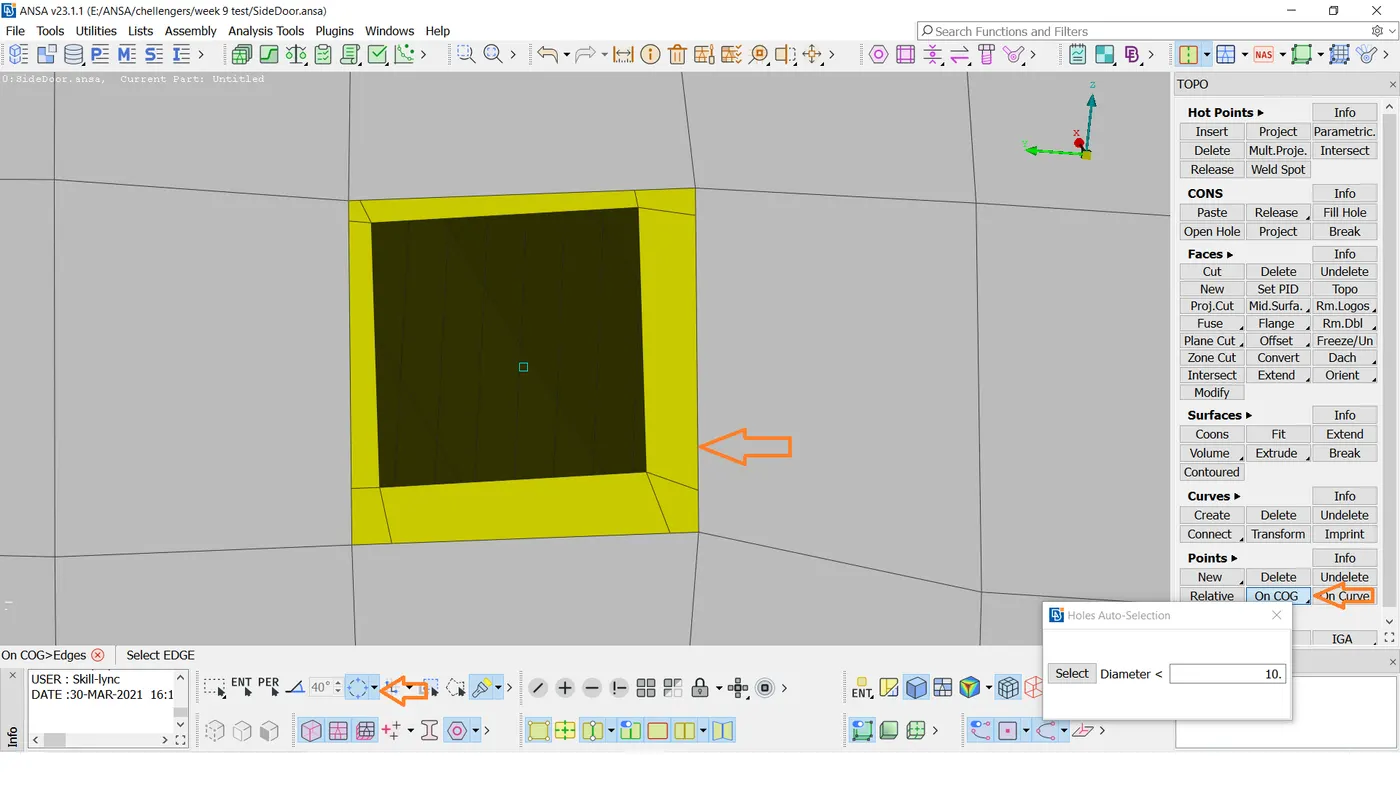
- Next, we Go to Topo-Points-On the COG option.
- Select the edge and create a point. This is shown in the figure below.
- After that create a bolt on the On COG using the connection tool manager.
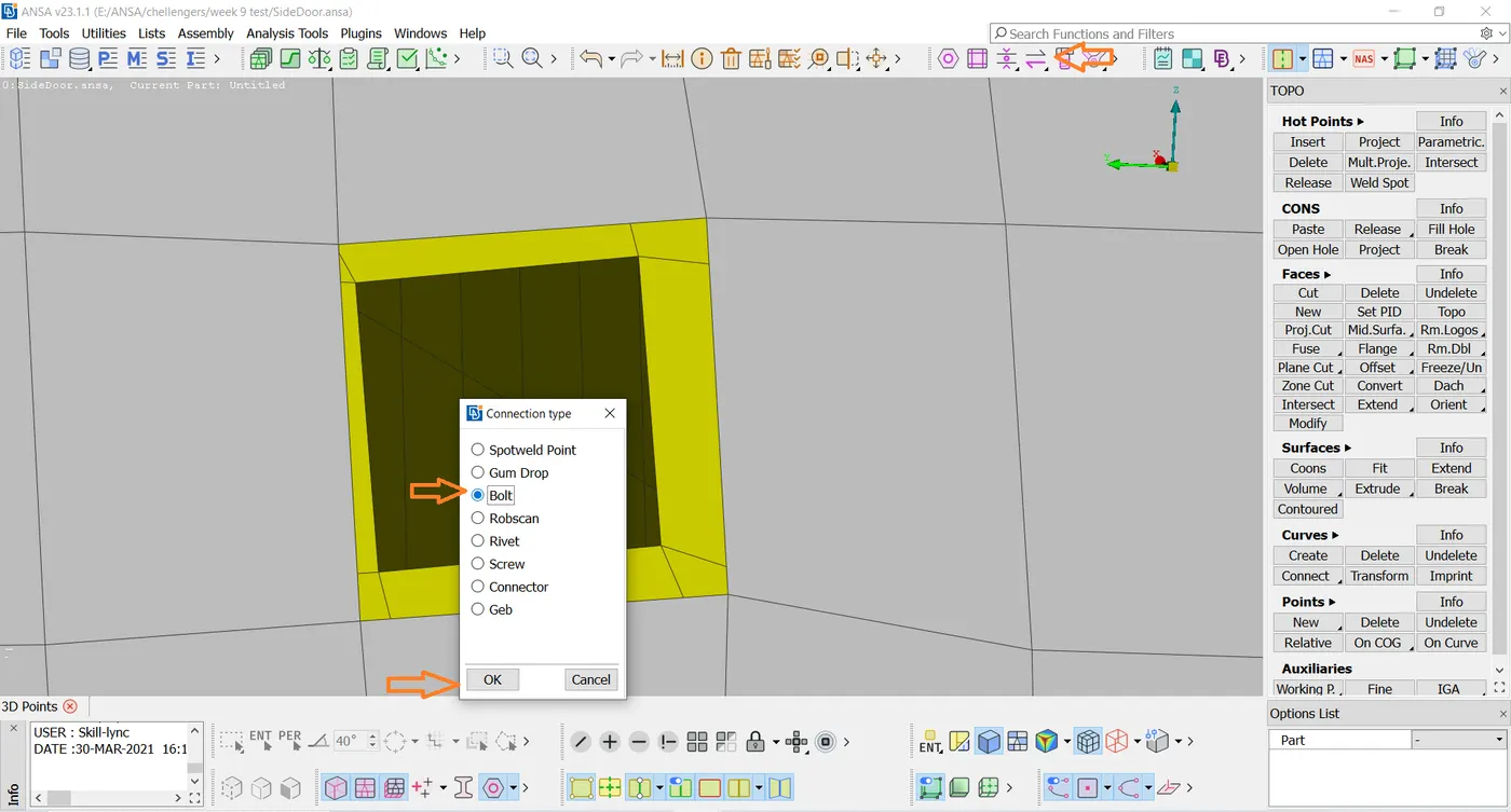
- Click OK It will change into the Bolt connection.
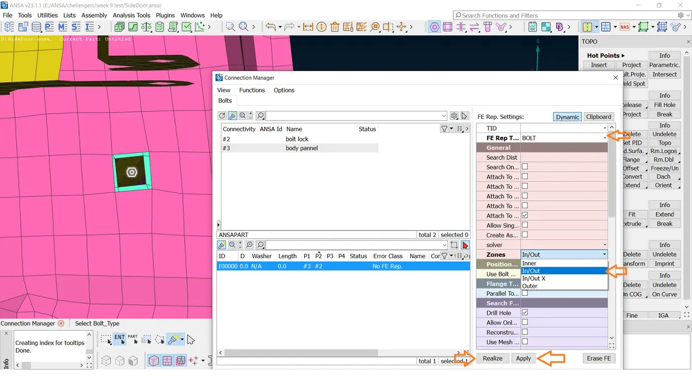
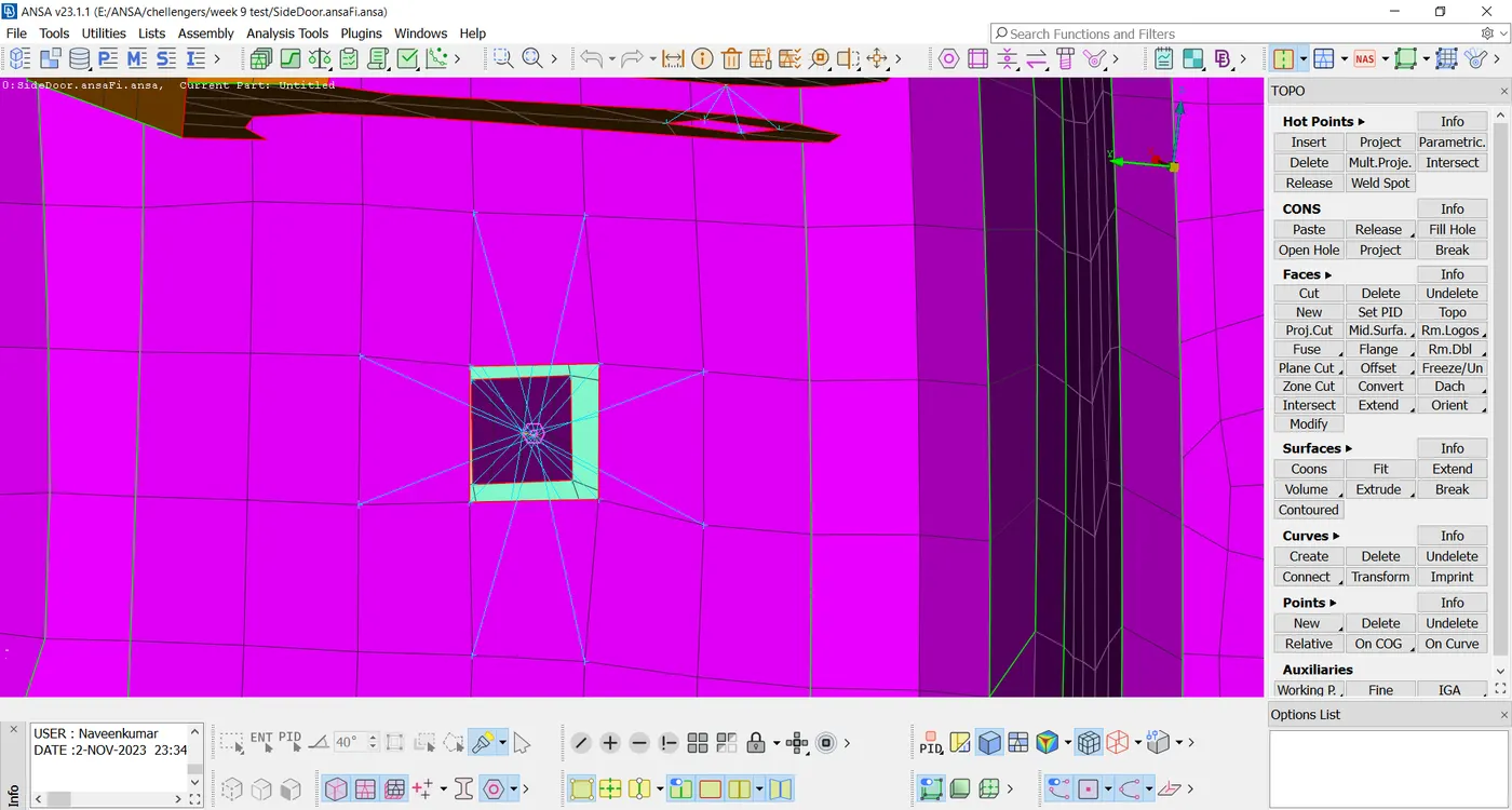
- After that, it shows the image below like a spider connection.
- Next, we sport-weld one of the link rods and joints.
- Go to Topo-Points-On the COG option. Select the edge and create a point. This is shown in the figure below.
- Now go to the connection option select the spotweld point and hit the middle mouse button. The connection manager window would pop up.
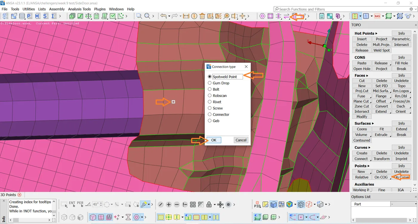
- Then select Spotweld point and click OK.
- Select the connection manager and select the spotweld point on the shown below image.
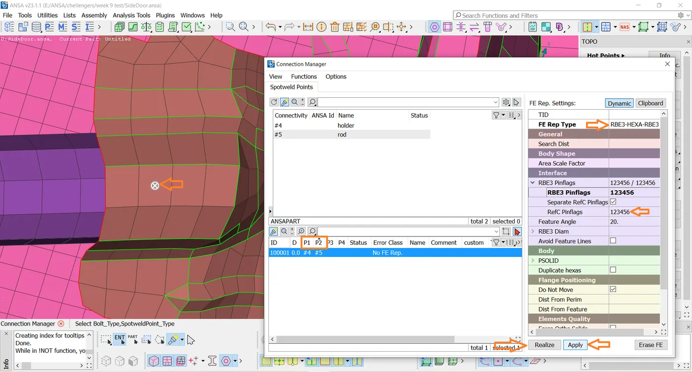
- In the connection manager window, select the parts that are to be connected using the F1 or shift &? option. Select FE Rep Type as RBE3-HEXA-RBE3 and enter the properties as shown in the figure below. (Here the position of the weld is taken for illustration purposes and in actuality, the position might vary)
- Create a PSOLID card for this connection and hit on apply and realize. The realized connections are shown in the images below.
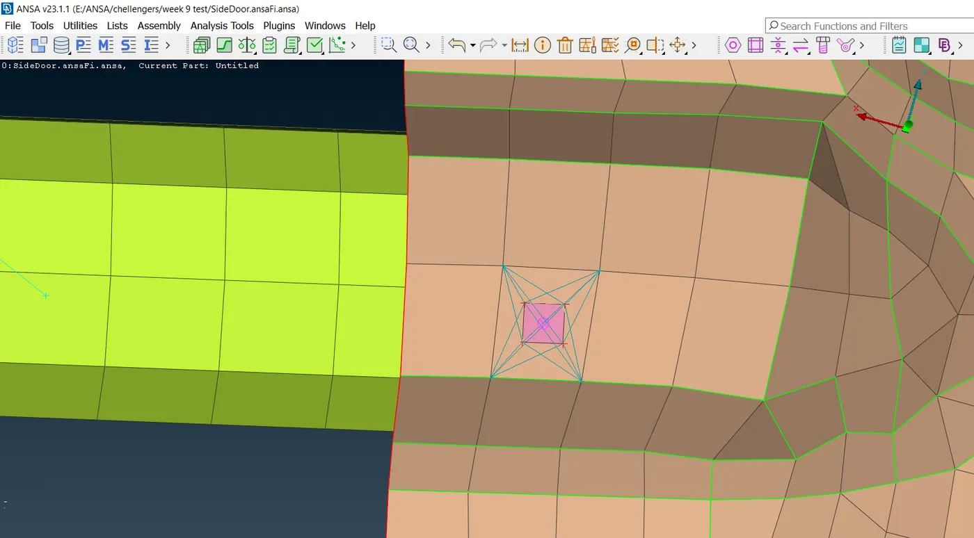
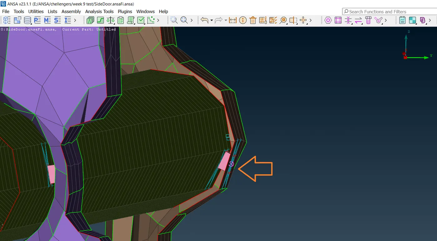
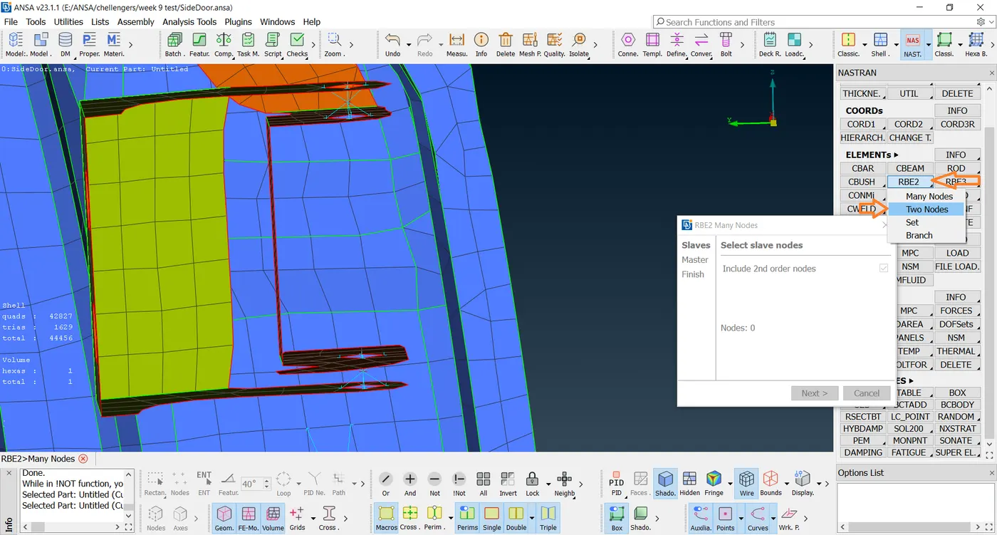
- Go to NASTRAN Deck-Elements-RBE2-Many Points Select the points to which RBE2 must be created.
- Here RBE2 is used for realizing hinge connection.
- This is shown in the figure below.

- Now go to Elements-RBE2-Two points Select the points as shown in the image below to realize the hinge connection.
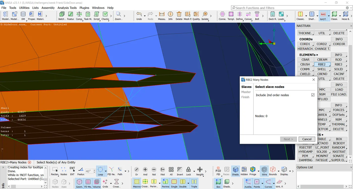
- Next, We Go to Elements-INFO-Info-Select the reb2 connection and give the necessary DOFs.
- This is shown in the image below.
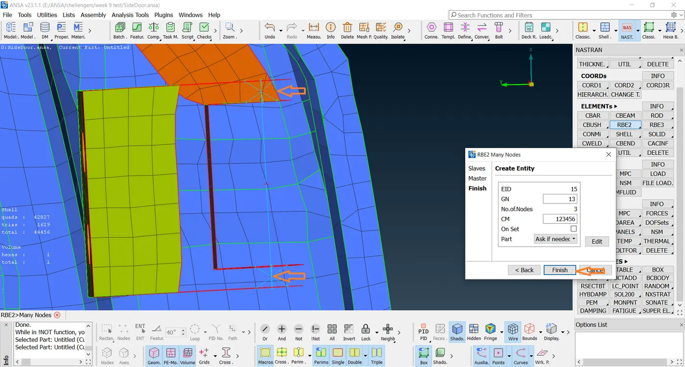
- The realized hinge connections are shown in the image below.
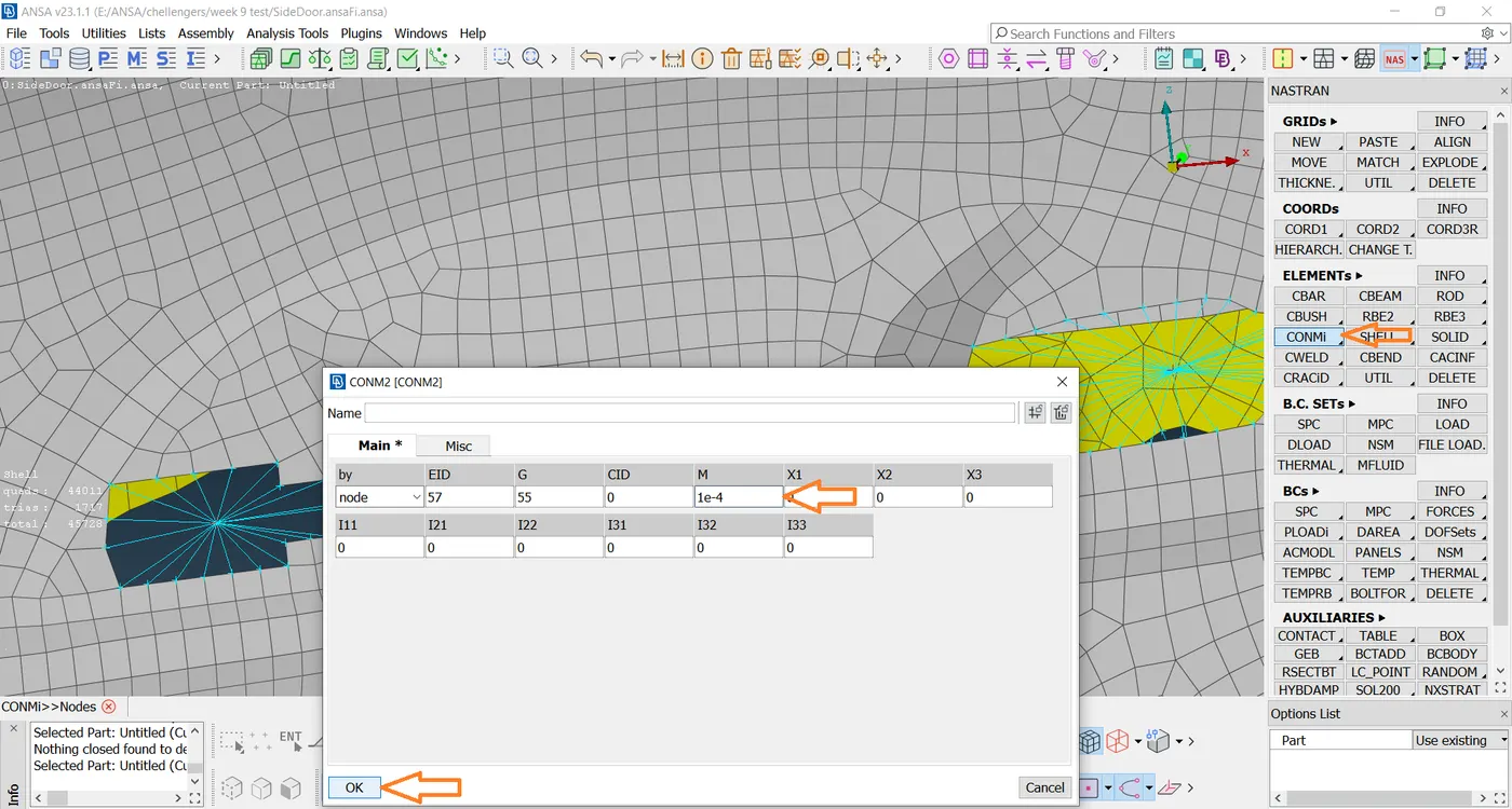
- For the door handle, the RBE2 connection is established and point mass is added using the CONMi option present in the elements deck.
- Select CONM2 and pick the necessary node to add the masses.
- It is to be noted that mass has to be entered in tonnes.
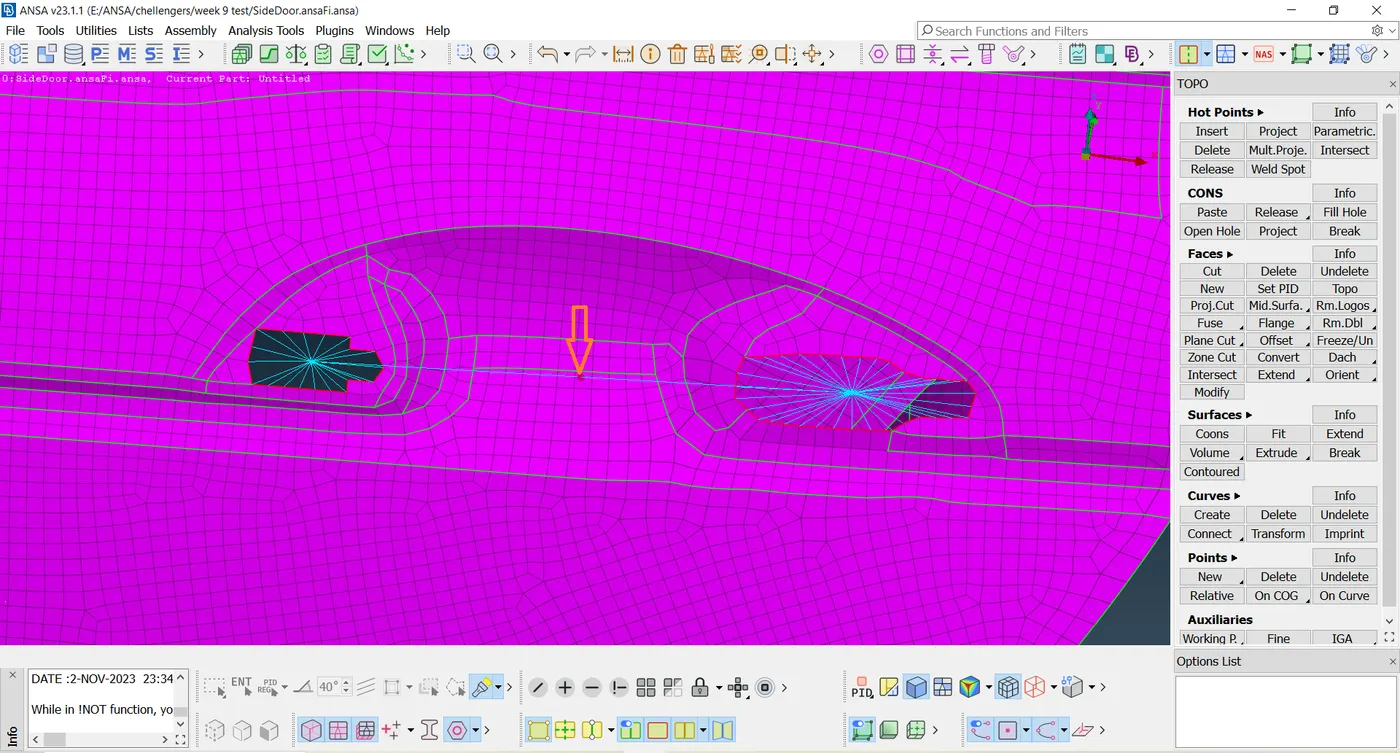
- The realized connection is shown in the image below.
- Next, we Go to the Mesh- Perimeters- Feat2Curve option and select the edges to create a curve.
- This is shown in the image below.
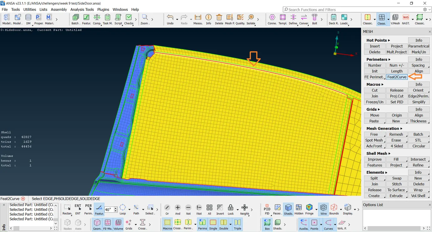
- Select the glass line by using the Feat2Cuve tool in the mesh option.
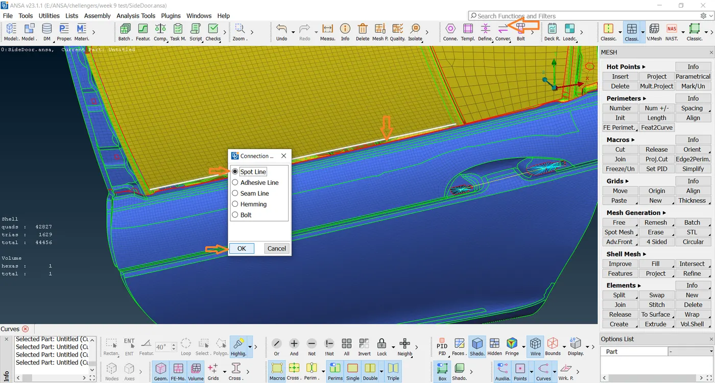
- Then click the middle mouse button & click OK As shown in the below image.
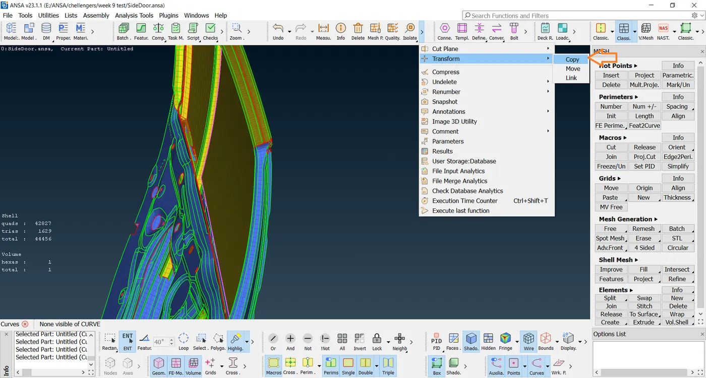

- Make a copy from the parent line as drawn in the image.
- And give dy and distance values.
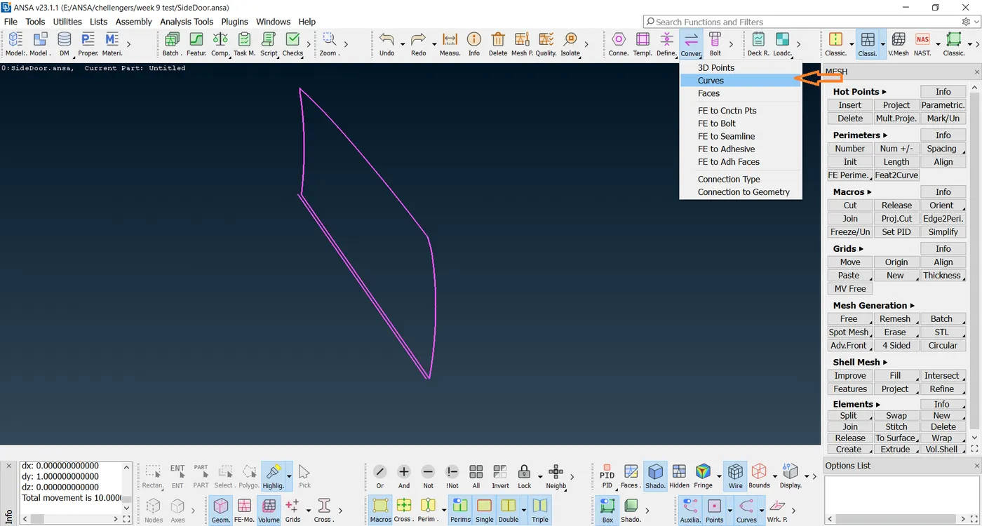
- Next, we Go to connection-select the spotlight-Middle mouse-Connection Manager.
- Select the parts to be connected using the F1 option. Set FE Rep Type as RBE3-CBUSH-RBE3 and enter the properties shown in the figure below.
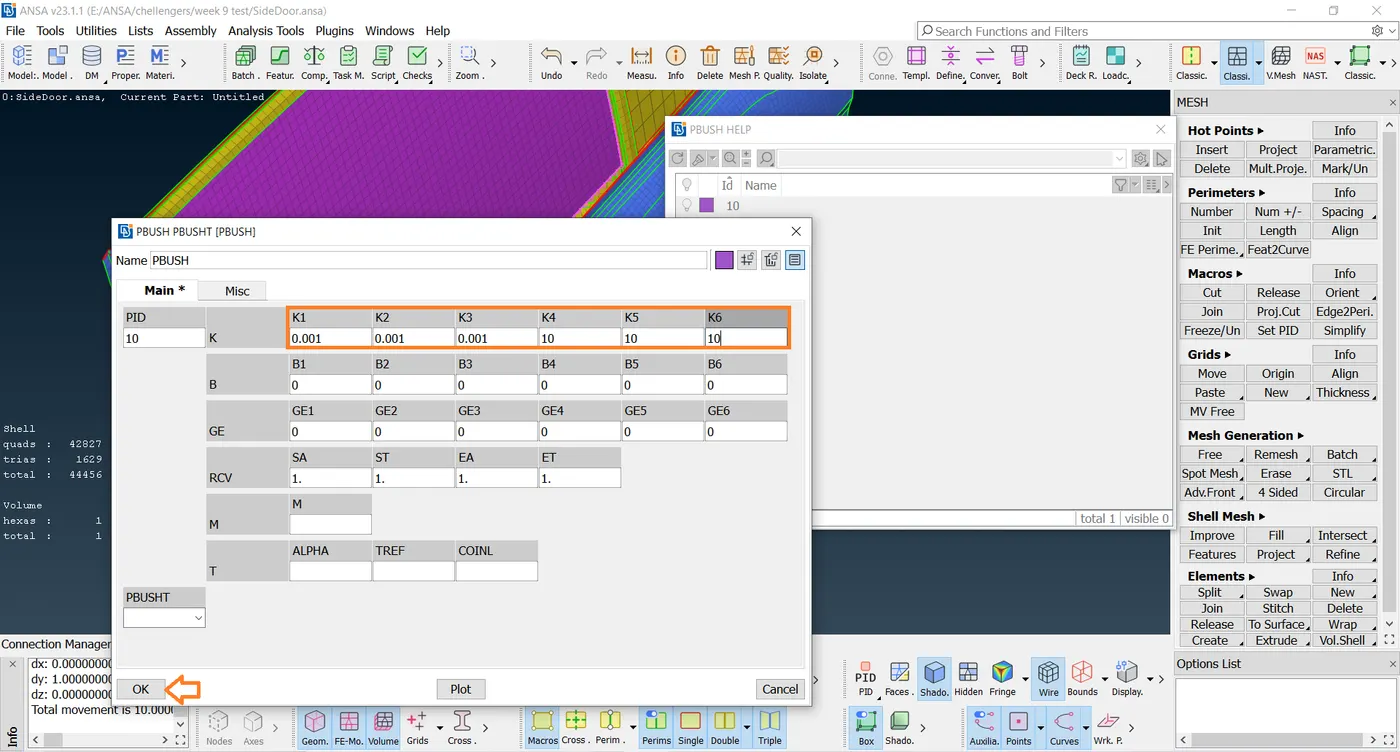
- Now click on apply and then realize the connection. Now go to the CBUSH property card select all the connections and hit on modify.
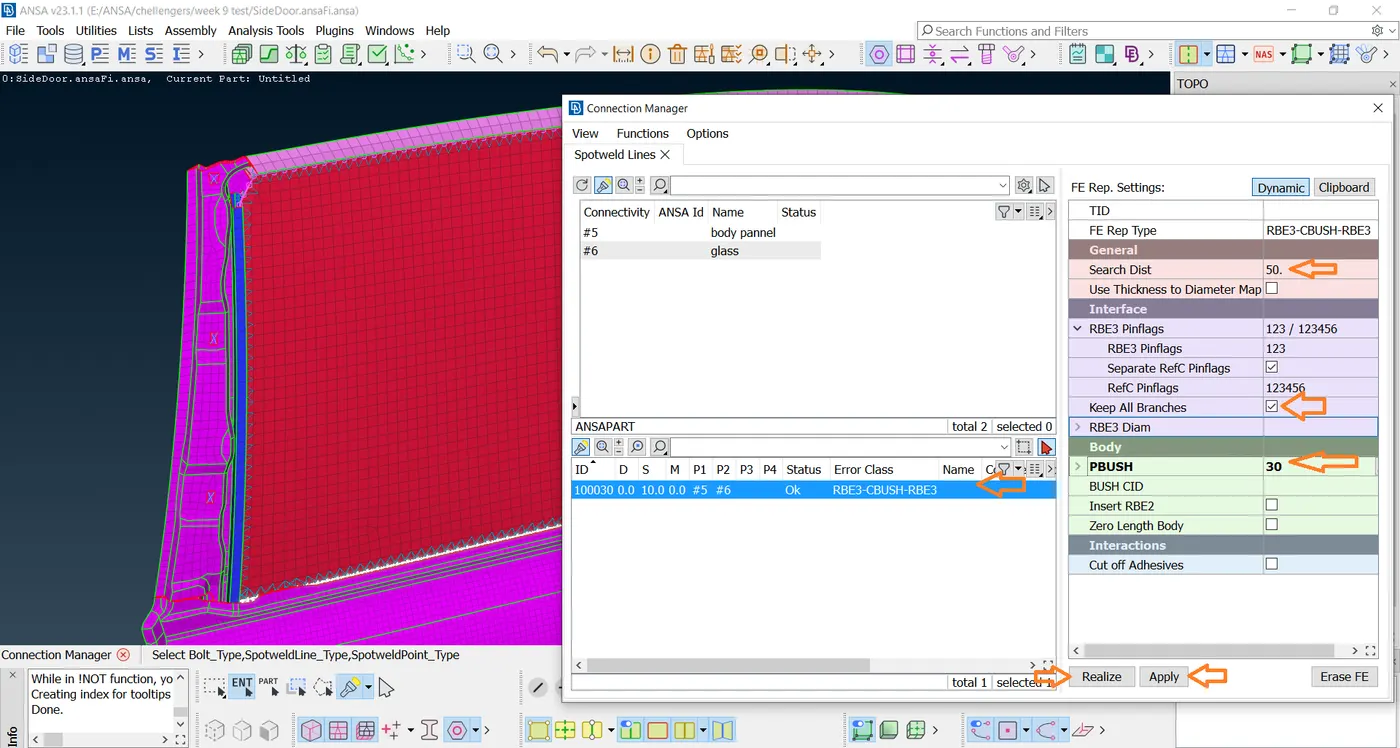
- Select the curve click the middle mouse button RBE3-CBUSH-RBE3 and search for dist 50, click Keep all branches, PBUSH.
- The modification parameters are shown in the figure below. (Orient - With Coord, CID as 0).
- This is done to orient the CBUSH connections to the global axis.
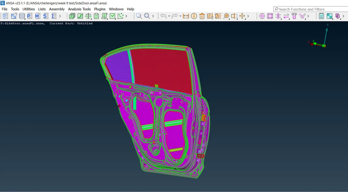
- Final outcome is shown in the above image.
LEARNING OUTCOME:
- In this challenge, various connections like BOLT, Spotweld, and CBUSH are learned.
- Learned to assign PID for various parts present in the model.
- Assigning of mass for the door handle is learned.
CONCLUSION:
- The PIDs are assigned to the various parts in the given model.
- Various connections like BOLT, Spotweld, and CBUSH are created and realized.
- All the given objectives are satisfied.