Week - 4 - 2D meshing for Plastic components
AIM
- To check for the geometrical errors for the given component.
- To extract all the mid surfaces of the given component with a suitable method.
- To mesh all components in the model with the given element Quality criteria. After meshing the part assigned thickness to the model.
|
S.No |
Quality Criteria |
Value |
|
1 |
Target/Average length |
1 |
|
2 |
Minimum Length |
0.5 |
|
3 |
Maximum Length |
3 |
|
4 |
Aspect |
3 |
|
5 |
Warpage |
15 |
|
6 |
Skewness |
45 |
|
7 |
Jacobian |
0.7 |
|
8 |
Minimum Quad Angle |
45 |
|
9 |
Maximum Quad Angle |
135 |
|
10 |
Minimum Tria Angle |
30 |
|
11 |
Maximum Tria Angle |
120 |
|
12 |
Tria Percentage |
15 |
OBJECTIVE
- Writing a detailed report on the meshing process and mentioning which method we used to extract the mid-surface.
PROCEDURE
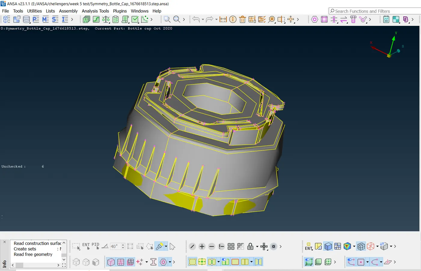
- The given component is shown in the below images.
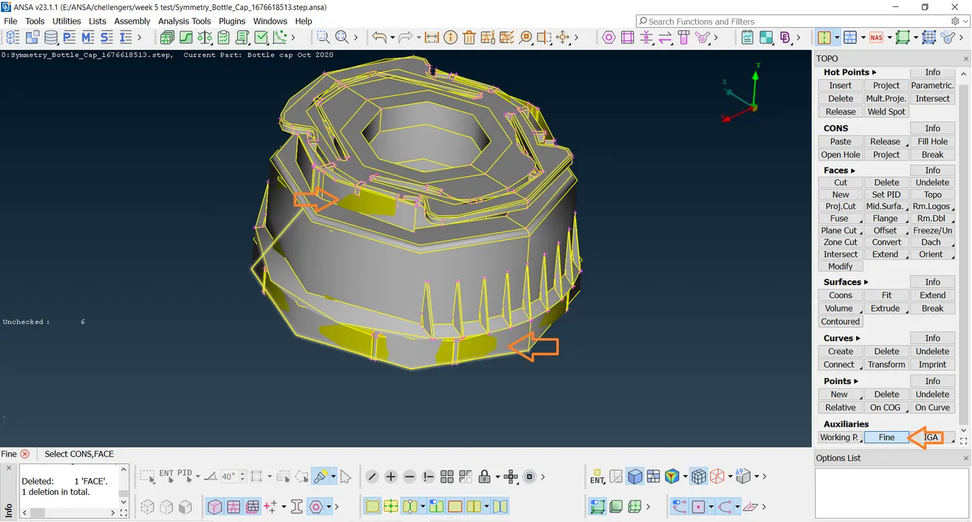
- In this given part more graphical errors occur, to refine by using the Fine tool to refine the part as shown in the below image.
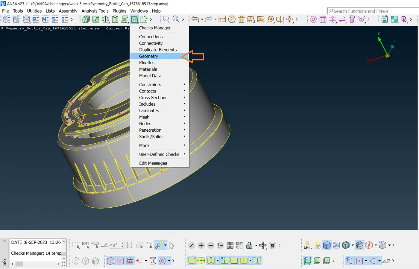
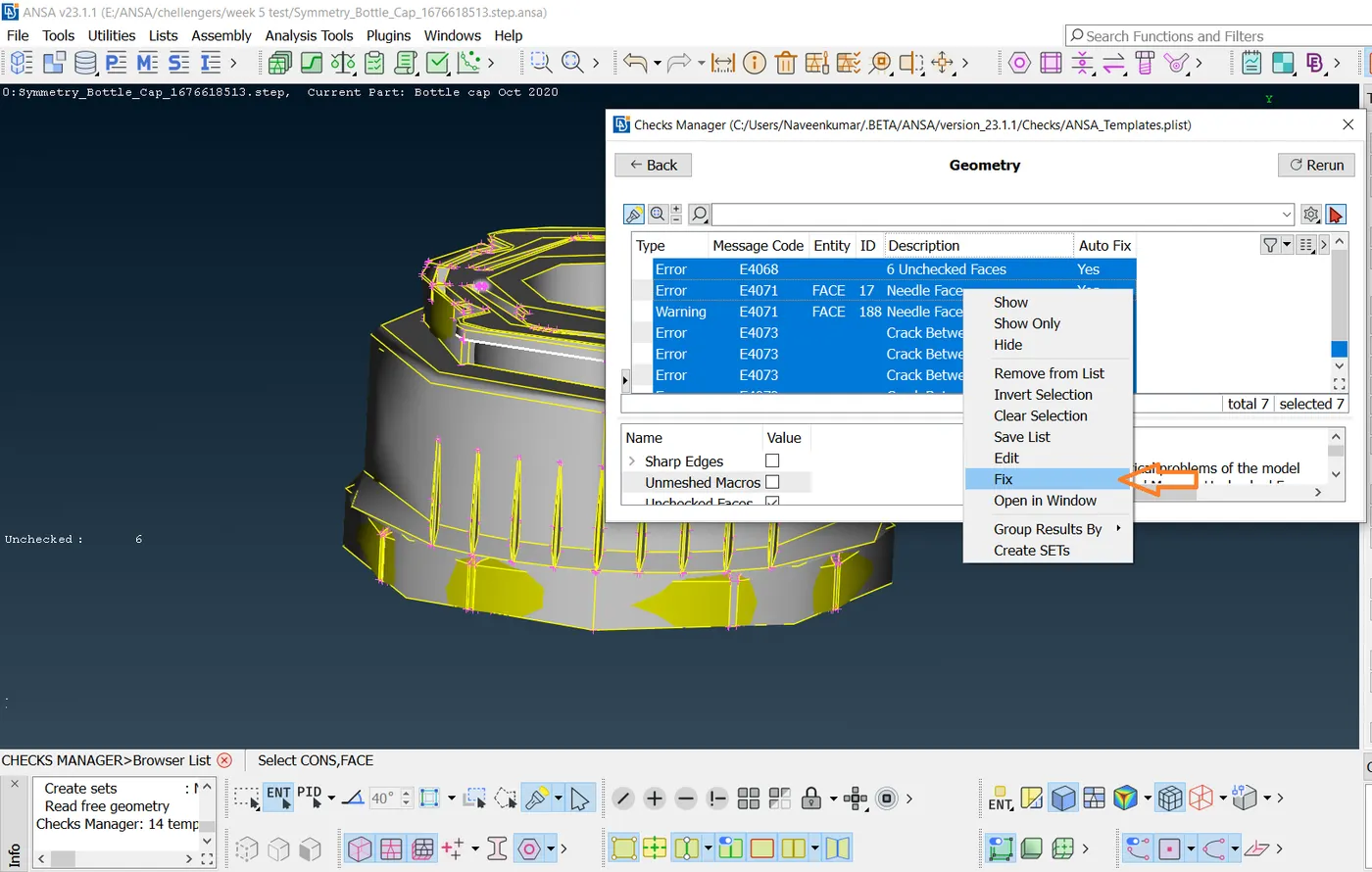
- Next, check the geometry of the component and then select all right-click, and then click Fix.
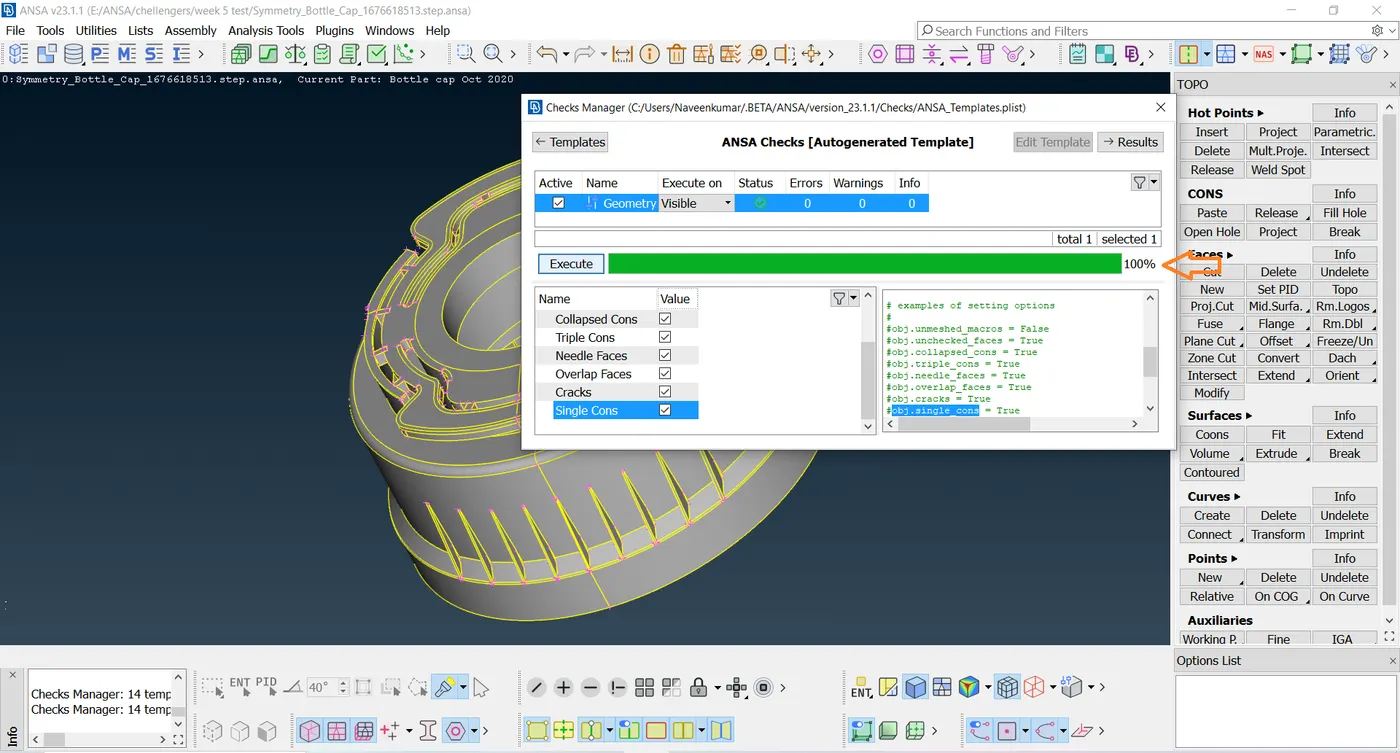
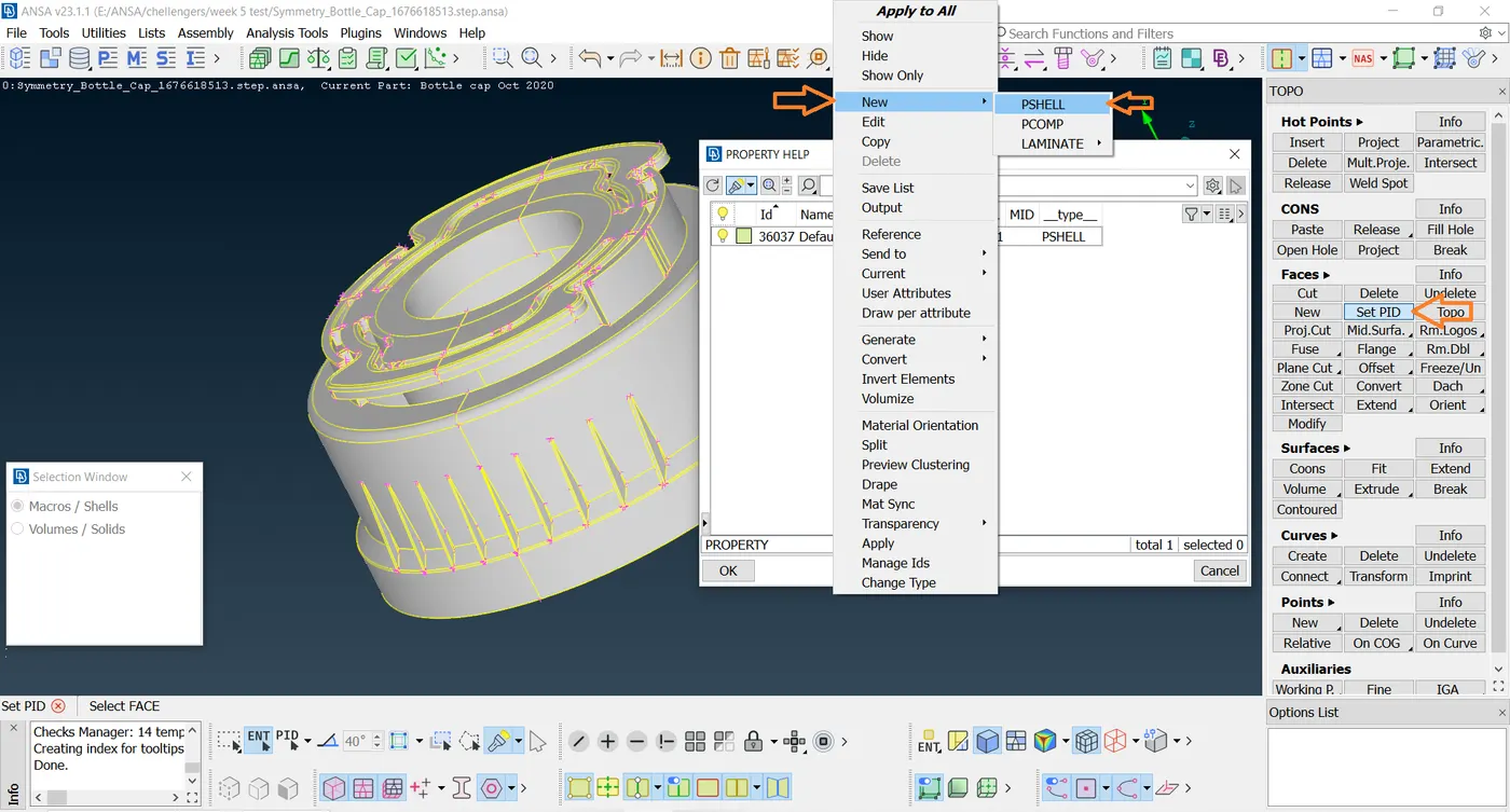
- Next, The PID is used to create a property of the particular model parts or the total model. To create a new PID or to check the existing PIDs.
- Click Lists - Properties.
- To create a new PID, right-click the dialog box, and the drop-down appears. Click New - PSHELL- PSHELL.
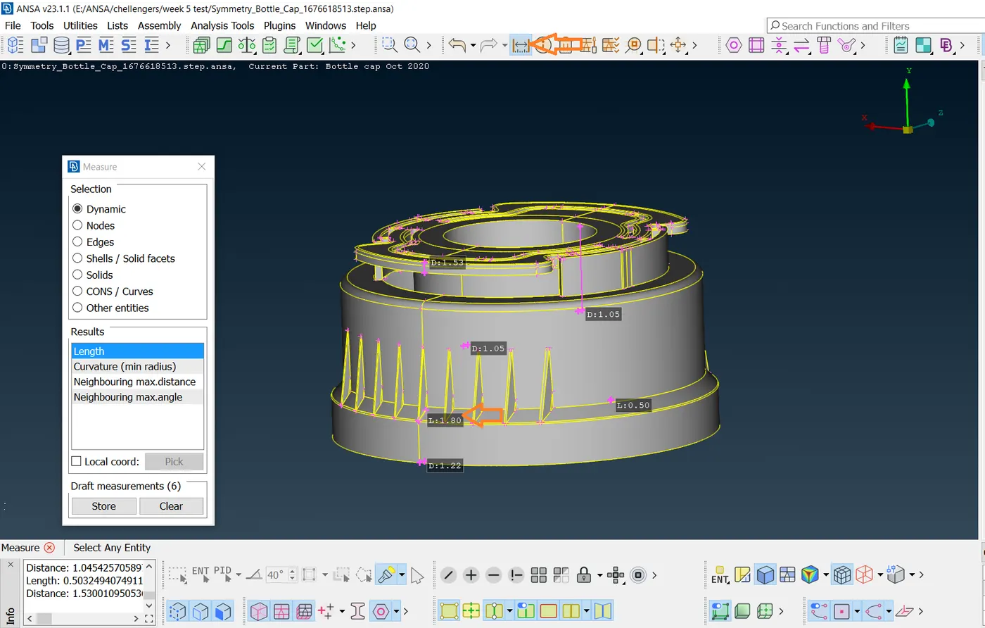
- To give the mid-surface location the thickness of the element, the model should be known to know the model thickness that the measure tool used. Click Utilities - Measure - Select the Nodes - Click Check the thickness at different locations.
- Mid-surface is created to use it to do the meshing as it does not affect the parent geometry but carries out the preprocessing simulation.
- The mid surface is created by using the module buttons in Topo Mode.
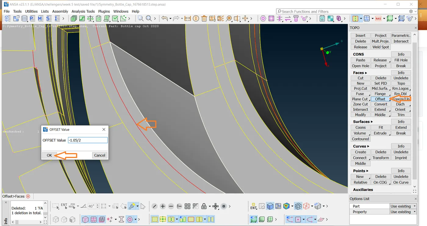
- In Module Buttons, Click Offset - Skin in Faces then click on the face for which the mid surface is to be created.
- Click middle- click on the mouse to confirm and a dialog box appears in which the mid-surface location is to be given.
- The offset value is given as the thickness of the selected surface divided by two and the direction in which the offset is going to be done is shown with an arrow symbol.
- In the sum area, there are different lengths occur.
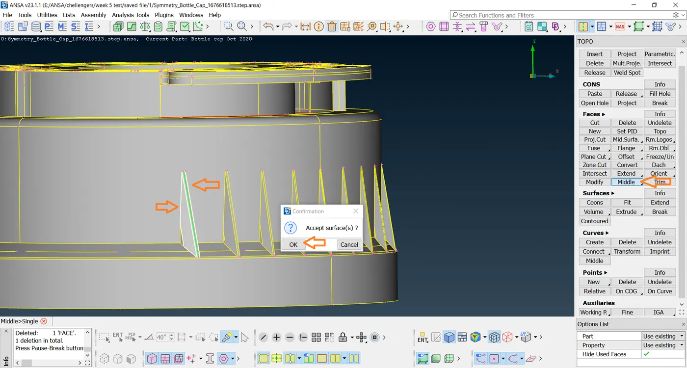
- The Middle tool to create a mid-surface is shown in the below image.
- Next, create the mid-surface for the remaining parts of the Bottlecap.
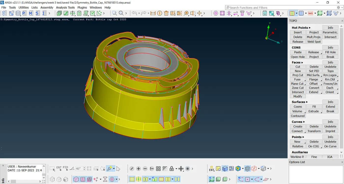
- Go to the Topo Face - Offset - select face - offset value - Ok as mentioned to create the mid-surface for remaining all components.
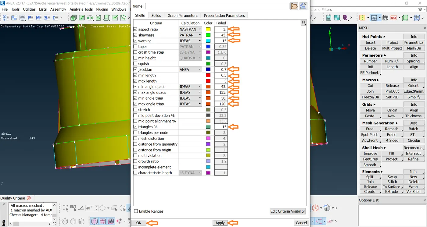
- Next, press the F11 key to fill the Quality criteria in the given.
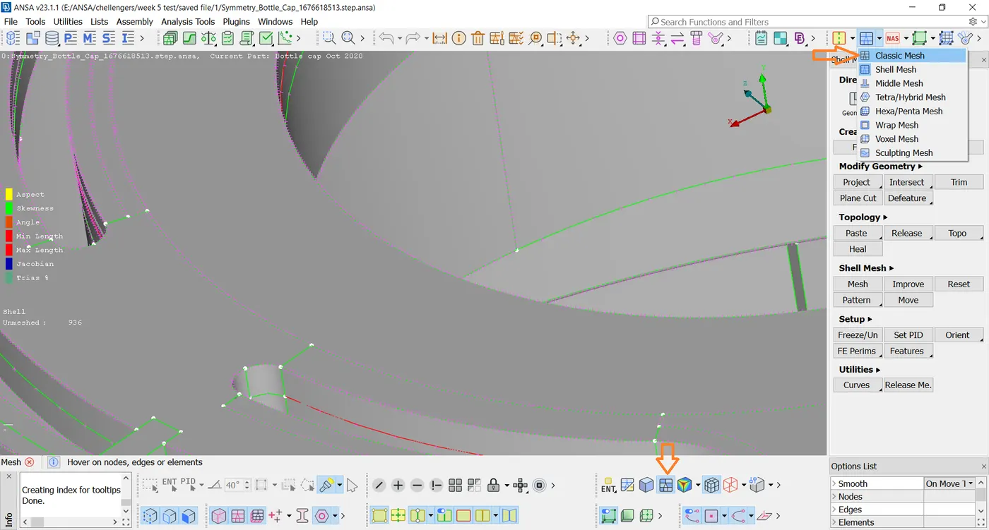
- Next, The Mesh-classic mesh-Besh -tool is used for meshing the surface of the parts.
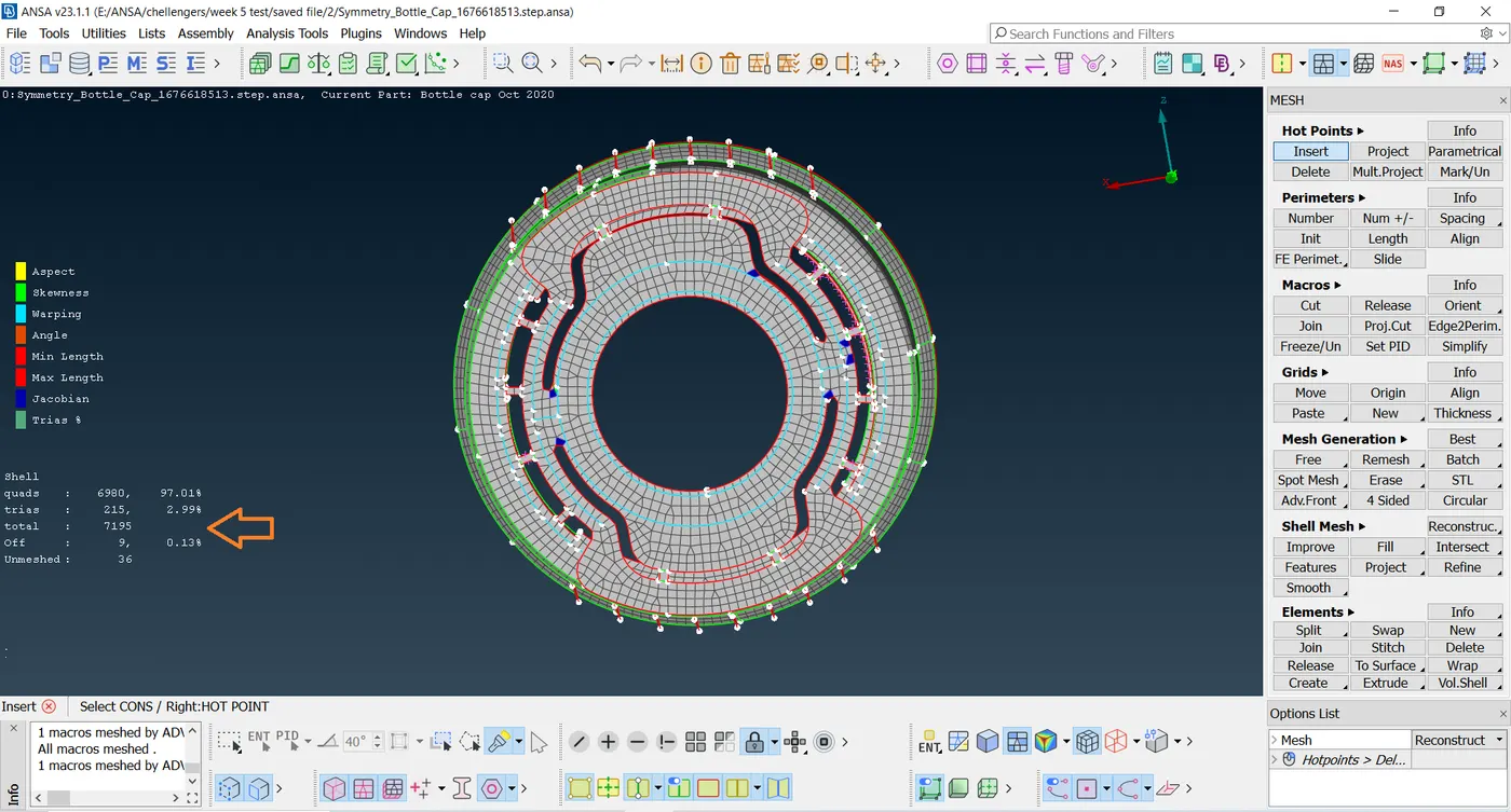
- To reduce trias and off by using Reconstruction, split, and swap tools.
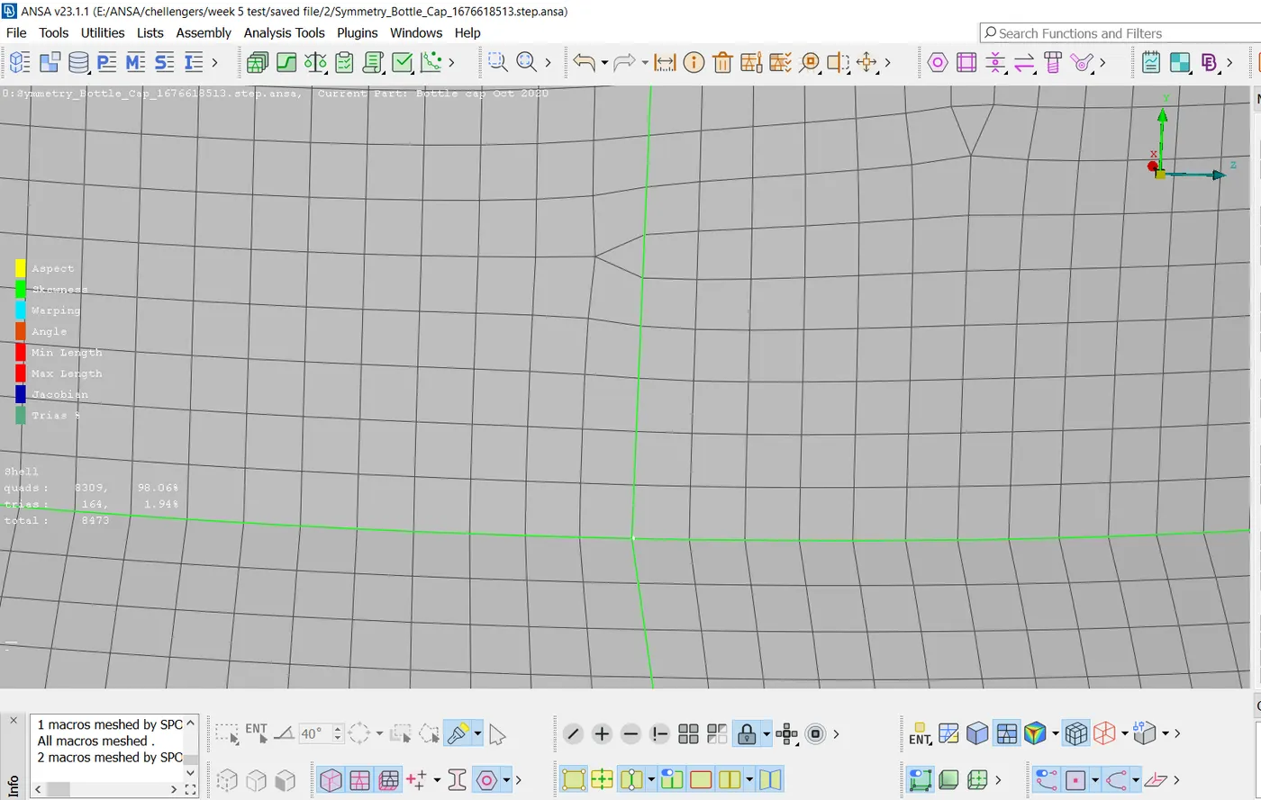
- The final mesh part is shown below.
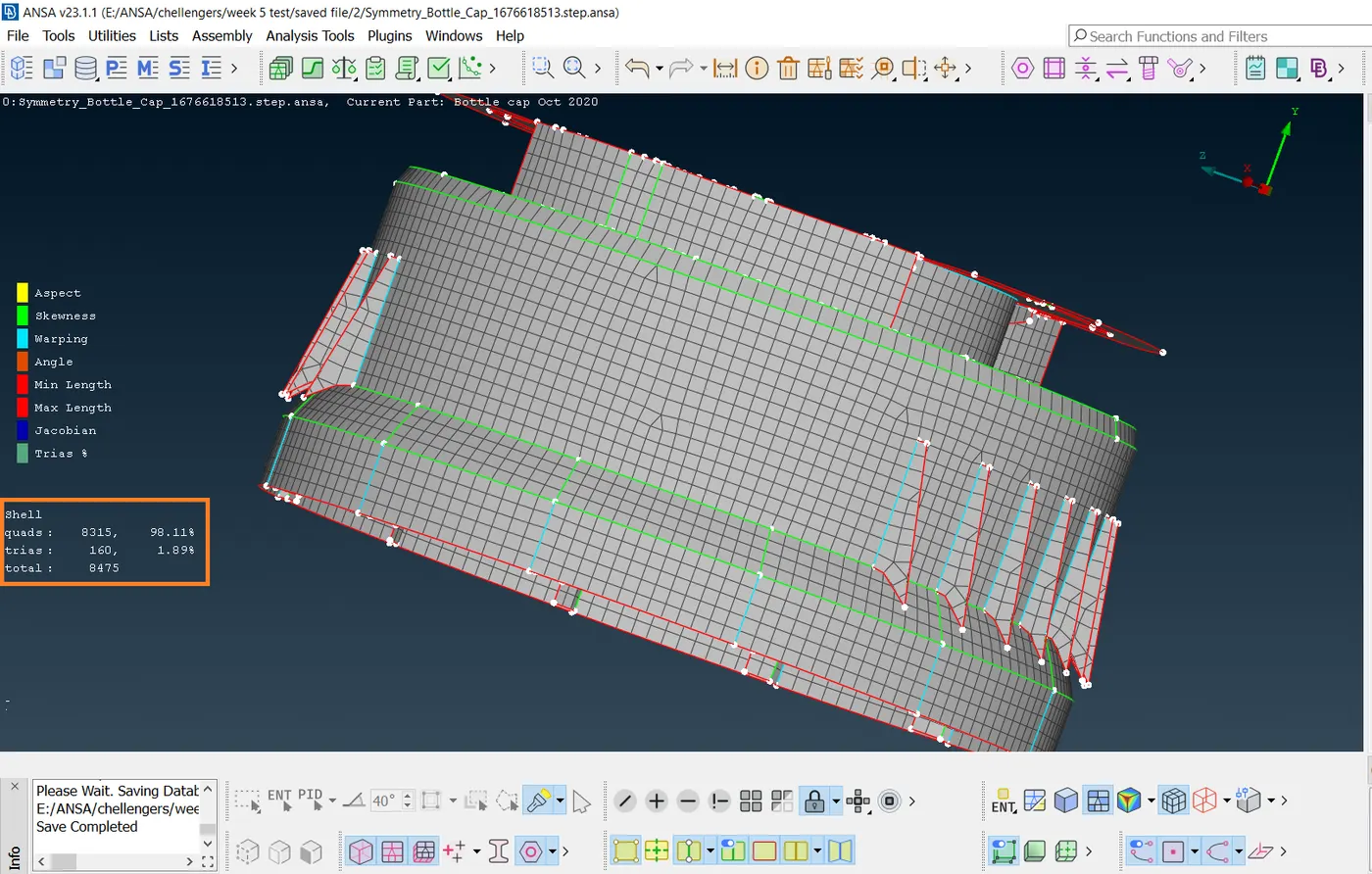
- Total = 8475, Quads = 8315, (98.11%), Trias= 160,(1.89%)
Learning Outcomes
- Geometric Clean-up.
- Topological Correcting.
- Creating of Mid Surface using Offset, Middle, Middle (Multi), and Middle( Curves).
- Creating the Mesh.
- Correction of mesh errors.
- Adding the Thickness.
CONCLUSION
- The given bottle cap model is meshed with given quality criteria, created mid-surface, and assigned various thicknesses.