Project 1 - Meshing of Floor Panel
AIM
To extract the mid surface, mesh the component with given quality parameters, and assign the thickness on a Floor panel.
OBJECTIVE
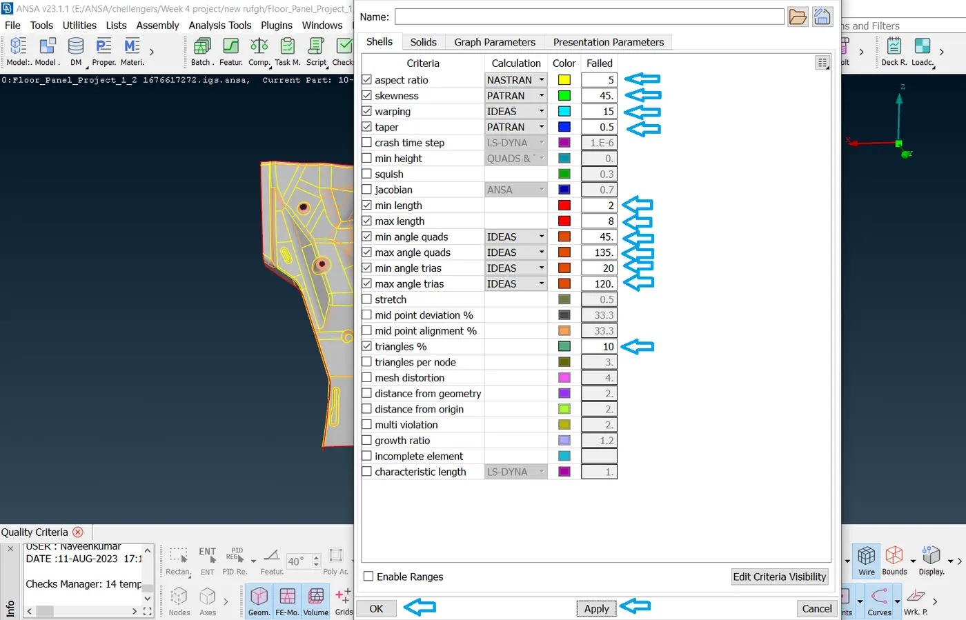
The below-mentioned quality criteria, mesh component is given below, and assign thickness:
Target Element Length = 5 Units
| S.N | Quality Criteria | Value |
| 1 | Aspect Ratio | 5 |
| 2 | Skewness | 45 |
| 3 | Warping | 15 |
| 4 | Taper | 0.5 |
| 5 | Min. Length | 2 Units |
| 6 | Max. Length | 8 Units |
| 7 | Min angle Quad | 45 |
| 8 | Max angle Quad | 135 |
| 9 | Min angle Tria | 20 |
| 10 | Max angle Tria | 120 |
| 11 | Tria % | 10 |
PROCEDURE
The Floor Panel geometry is open in the ANSA for Meshing, the file is available in STP format, The Floor Panel has four different parts which are locked differently to see each piece individually to extract the middle surface and mesh the component.
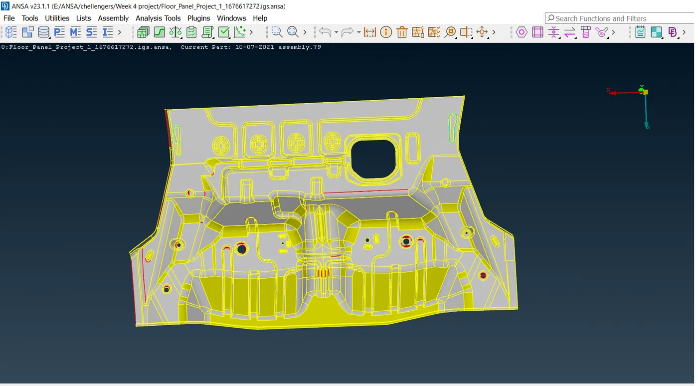
- The first step after importing the model is to properly analyze and understand the geometry.
- When a CAD model is imported into the ANSA, there might be several geometrical errors like missing/distorted surfaces, intersecting surfaces, etc. due to the format conversion process or inherent bad model. And, it is important to clear all these errors before starting meshing. So, the next step is to clean up the geometry.
- To ensure that all the surfaces are connected properly Faces-Topo tool is used for all the edges of each component at a time.
- Next, a geometry check is performed by going to Checks-Geometry and running it for parameters as shown in the image below.
- Next, Another image shows the errors detected.
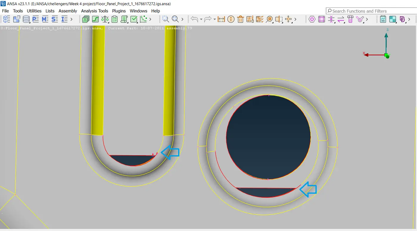
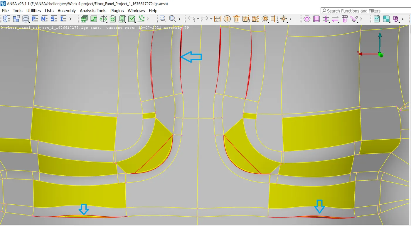
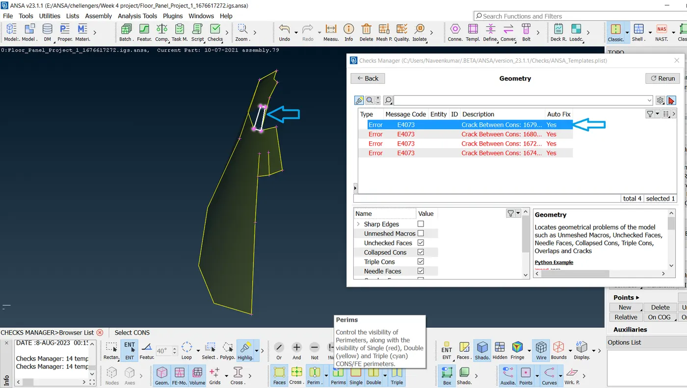
- Most of the errors were fixed automatically by right-clicking on the error Fix.
- Next, the orientation of all the faces is modified by going to Faces-Orient. This ensures that all faces are oriented similarly.
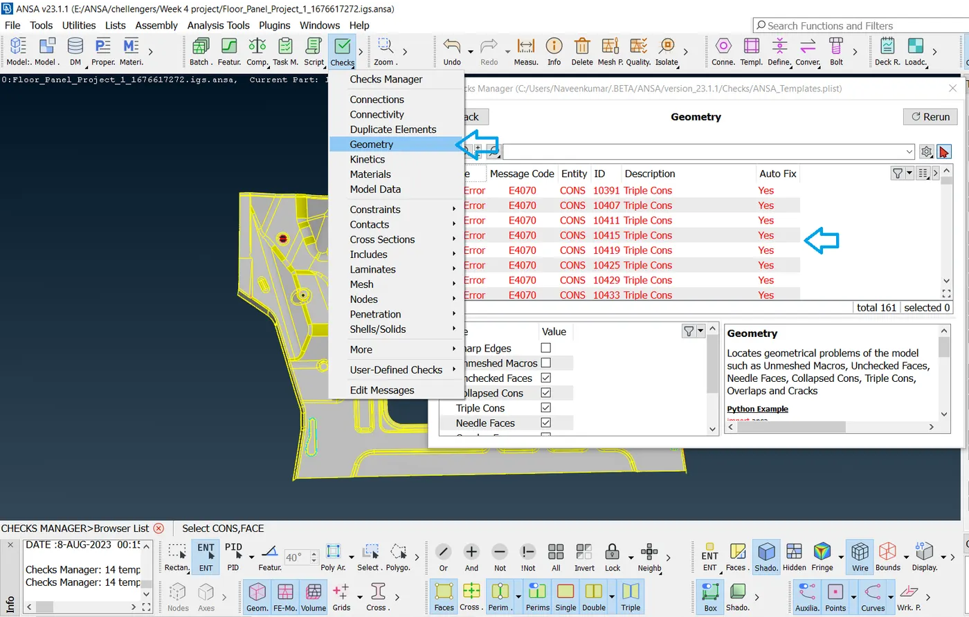
- And then select all error cons as shown in the list and right-click and select fix
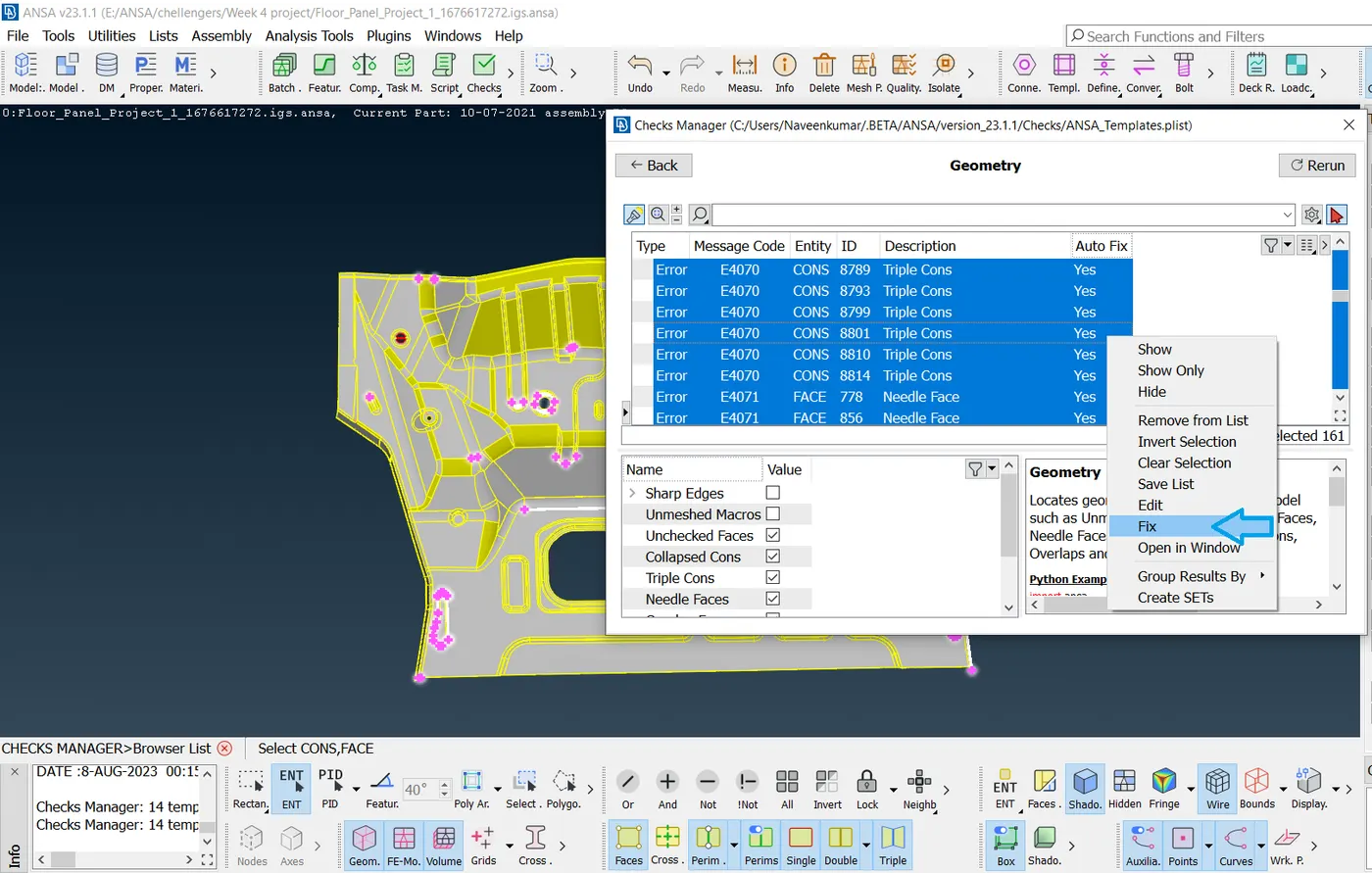
- Most of the errors were fixed automatically and some errors count fix that kind of errors were fixed manually.
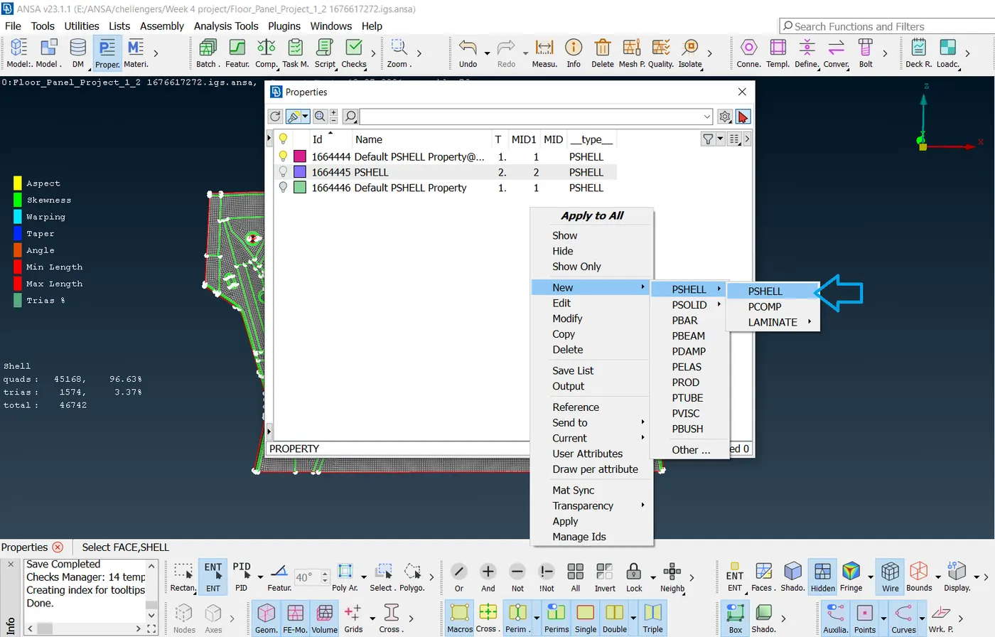
- Geometry clean-up is done after that clean-up creates new property PSHELL.
- After creating a new PSHELL the mid-surface is extracted using the Offset tool by going to Mid-surface and selecting all the surfaces on one face.
- Then, half of the thickness is given as the offset value, and the direction is checked.
- Now, the property is assigned to the extracted mid-surface by going to Faces-Set PID and assigning it to the respective property.
- Similarly, all mid-surfaces are extracted and property assigned for all the components.
- The Outer panel and Inner panel (except one surface) are symmetrical, and only half the mid-surface is extracted.
- Similarly, both hinges are mirror images of each other, so the mid surface is extracted for only one hinge.
- Again, the extracted mid-surfaces are checked for geometric errors and fixed.
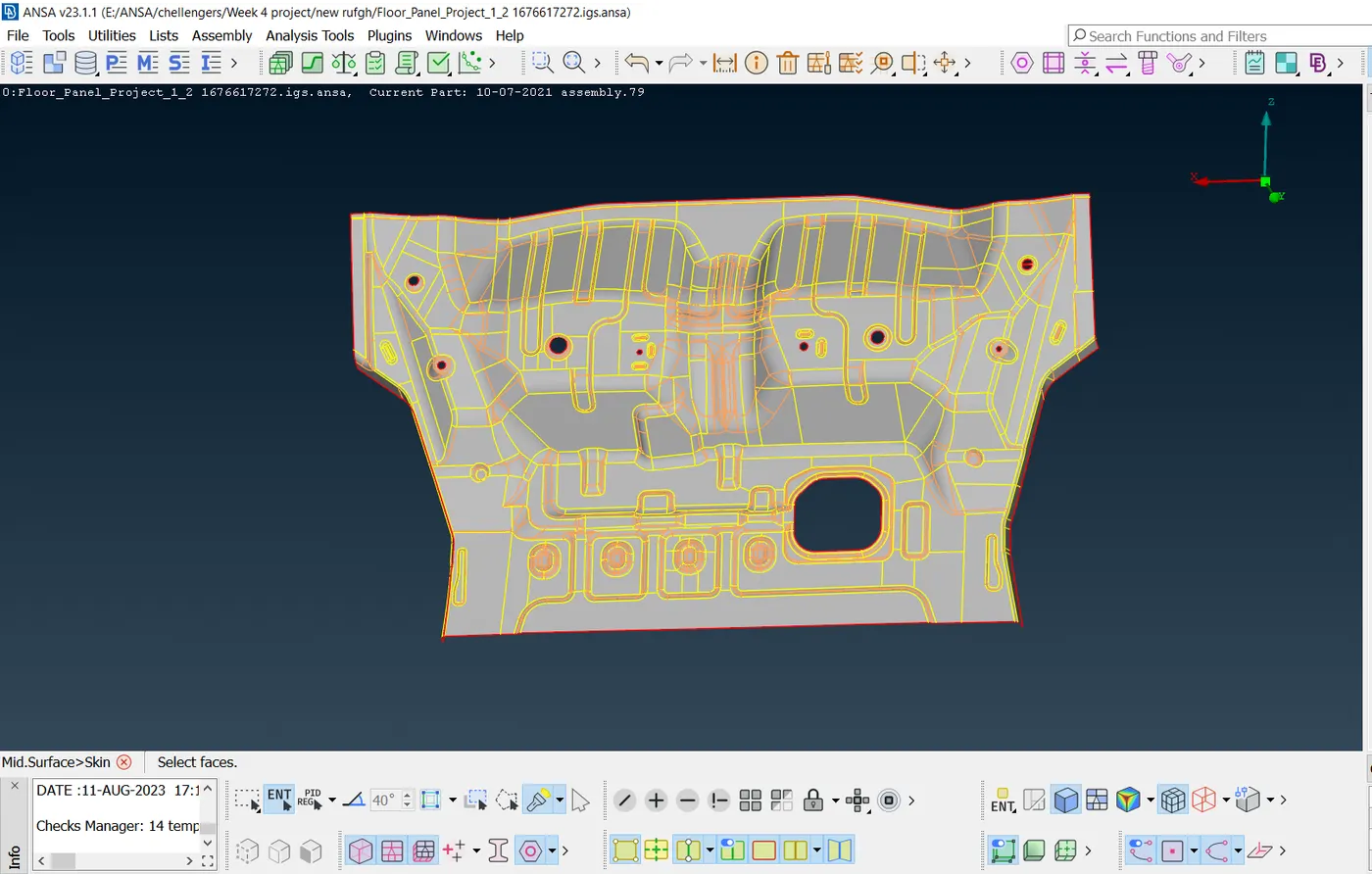
- The final extracted mid-surfaces are shown below.
- Mesh parameters are configured by going to Mesh Parameters.
- Quality criteria are configured by going to Quality Criteria.
- And, the quality criteria file is saved for future reference.
- The created quality criteria parameters are shown in the image below.
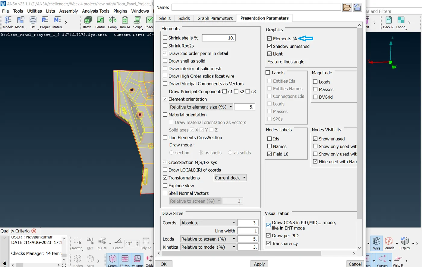
- After giving the value of Quality criteria and then clicking Presentation parameters on the same Tab as shown below image.
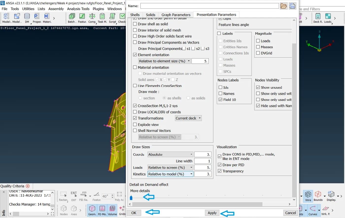
- Meshing is done using the Mesh Generation by Best tool. This tool generates the mesh using the best algorithm applicable.
- Then, the created mesh is refined using the Shell Mesh>Reconstruct tool. It is ensured that there are no rotating quads. Also, trias are kept as low as possible.
- While dealing with trias, the following things need to be ensured.
- No back-to-back trias touching each other
- No opposite trias
- No trias touching the edges
- No trias on a feature
- Low concentration of trias in a region.
- To deal with trias, the following tools are used,
- Grid-Paste, to paste the nodes and move tria backward
- Split- tool, to split an element and move tria forward
- Swap- tool, to move the tria left or right
- Join-tool, to join two trias to make a quad
- After modifying the mesh, the Shell Mesh-Smooth tool is used to smoothen the flow of the mesh. Any elements failing for quality criteria are also fixed by either re-meshing or smoothing the elements.
FINAL MODEL IMAGE
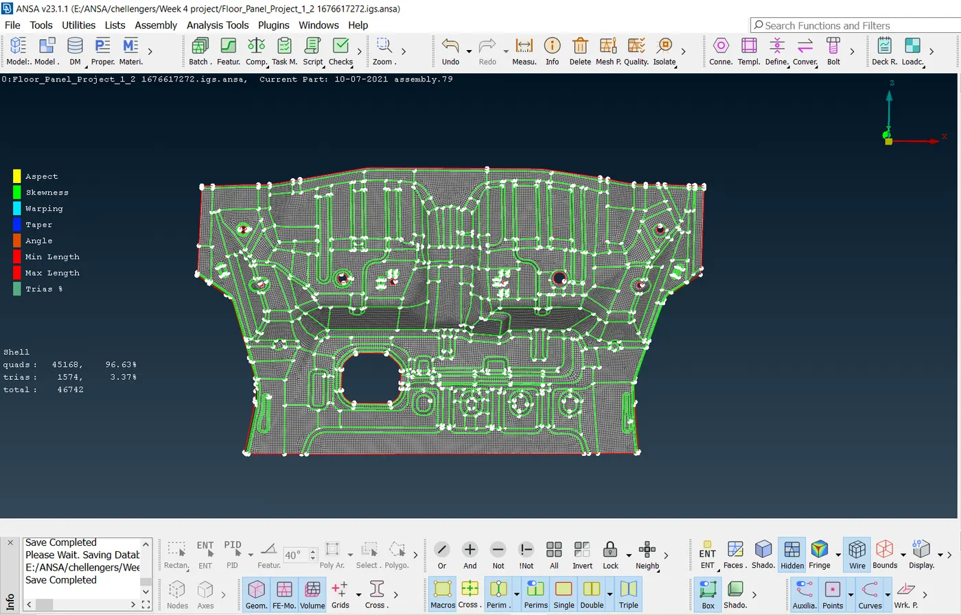
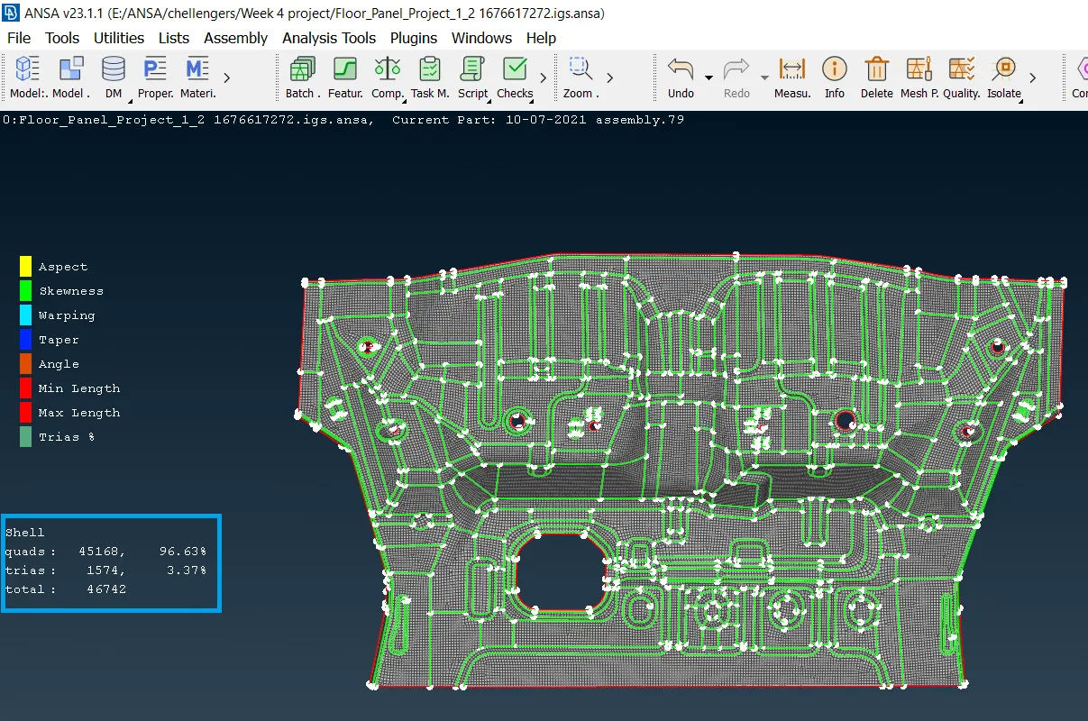
- The above image shows that the Quads 45168 of a total Quads of 46742 which is 96.63%
- And show low trias 1574 which is 3.37%
CONCLUSION
Geometry cleanup, mid-surface extraction, and 2D meshing of the given Floor panel model were successfully done. And all the elements pass the quality criteria. All the features in the model are captured properly with good mesh flow. Tria concentration is kept low.
File Link: https://drive.google.com/file/d/10LAOPm3T8UqlCamXUOsHWSME7VAeC2U5/view?usp=sharing