Week-7 : Converting a detailed engine model to a FRM model
AIM:
- Explore tutorial number 9 and write a detailed report
- Build FRM Model for following configuration using FRM builder approach
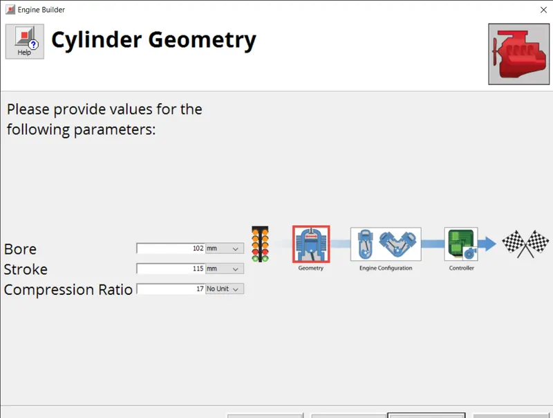
- Bore 102 mm stroke 115 mm CR 17
- No of cylinder 6
- CI engine
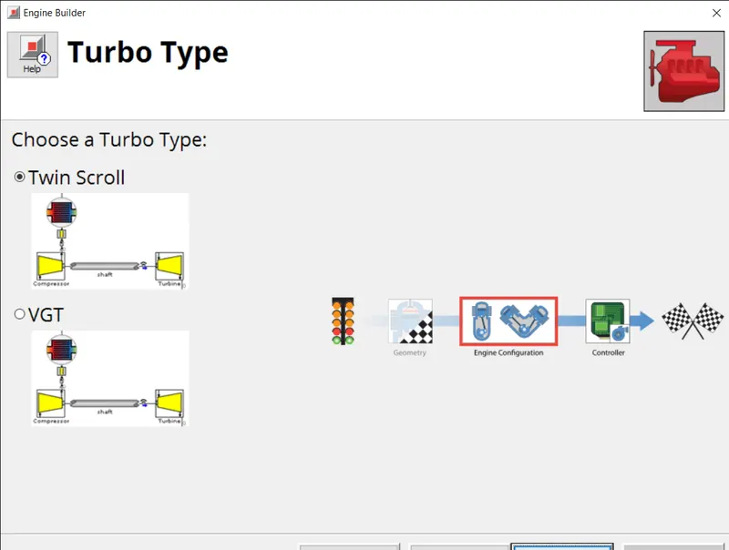
- Twin Scroll Turbine
- GT Controller
- Run all cases
INTRODUCTION:
FAST RUNNING MODEL:
Fast Running Engine Models are dynamic, fully-physical engine models that are designed specifically to run fast. While high-fidelity engine models are commonplace in the engine performance department, they are often too slow running to incorporate into system level models where long transient events may be simulated, or where the simulation model must respond faster than real-time, such as for HiL (Hardwarein-the-Loop) simulations. When simulation speed is of priority, high-fidelity GT-POWER engine models can be simplified into FRMs using a standard conversion process. It is up to the user how far to simplify the model, depending on the accuracy-vs.-runtime requirement.
FRMs are able to achieve such fast run times by two means: (1) increasing the simulation time step size, and (2) decreasing the number of calculations per time step. These two means are often accomplished at the same time by lumping various flow volumes together which will reduce the total number of subvolumes and also allow for a larger time step size by increasing the effective subvolume length (which is responsible for the time step size). In addition to simplifying and combining flow volumes, there are additional solver options that can reduce the number of calculations per time step and, thus, further decrease the run time without changing the time step size.
1. Explore tutorial number 9 and write a detailed report
Launch GT-ISE and open the file SI_4cyl_GDI_Turbo-WOT.gtm from 'File' -> 'Examples' -> 'Engine_1D_Gas_Exchange_Combustion' -> 'Gasoline' -> 'SI_4cyl_GDI_Turbo'.
This model is a 4-cylinder 2.0 liter turbocharged Gasoline Direct Injection (GDI) engine. The turbine wastegate is being dynamically controlled in order to target BMEP. A full-load speed sweep is being simulated, from 5000 RPM down to 1000 RPM. A semi-predictive charge air cooler is included such that the outlet temperature is predicted as a function of inlet gas temperature and mass flow rate, coolant temperature, and charge air cooler effectiveness.
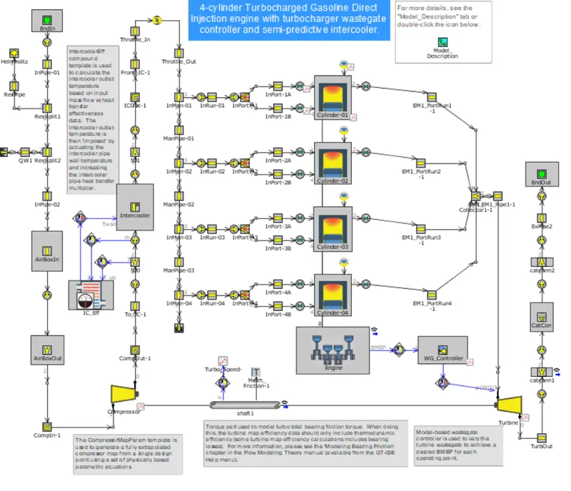
STEP 1: EXHAUST MANIFOLD
In the first step the exhaust manifold is simplified where the highest gas velocities occur, which in turn restricts the time step.
STEP 2: EXHAUST PIPES
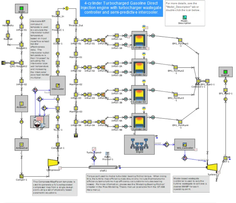
For the second step of model simplification, the exhaust pipes downstream of the turbine will be simplified. The pipe at the outlet of the turbine is combined with the catalyst volumes into a single flowsplit part.
STEP 3: INTAKE MANIFOLD
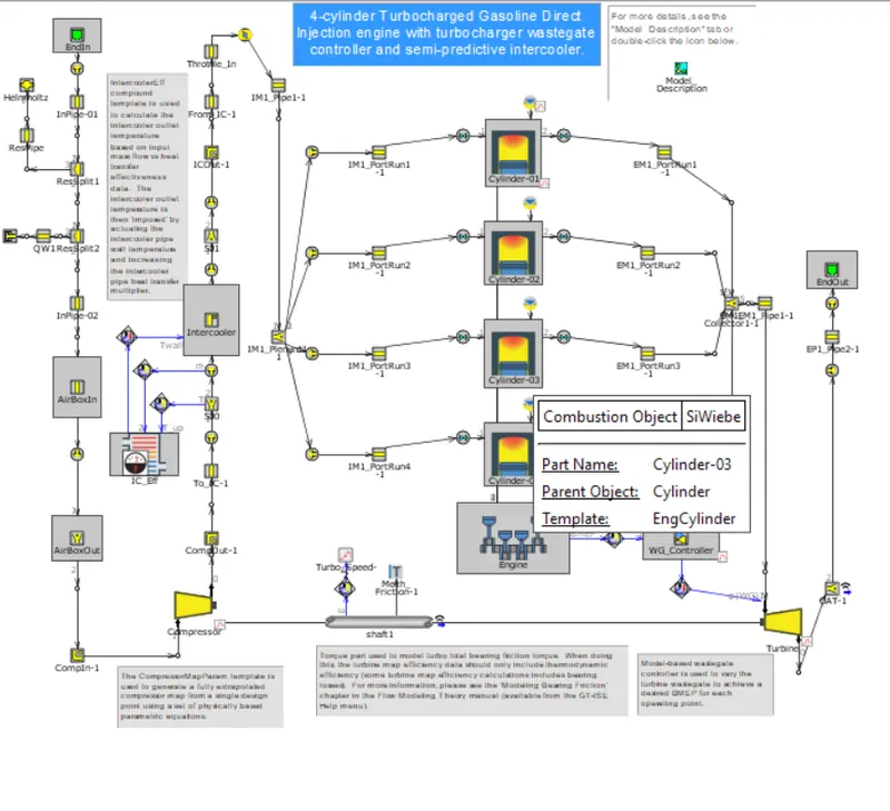
The intake manifold is modified into a single volume.
STEP 4: COMPRESSOR OUTLET PIPES
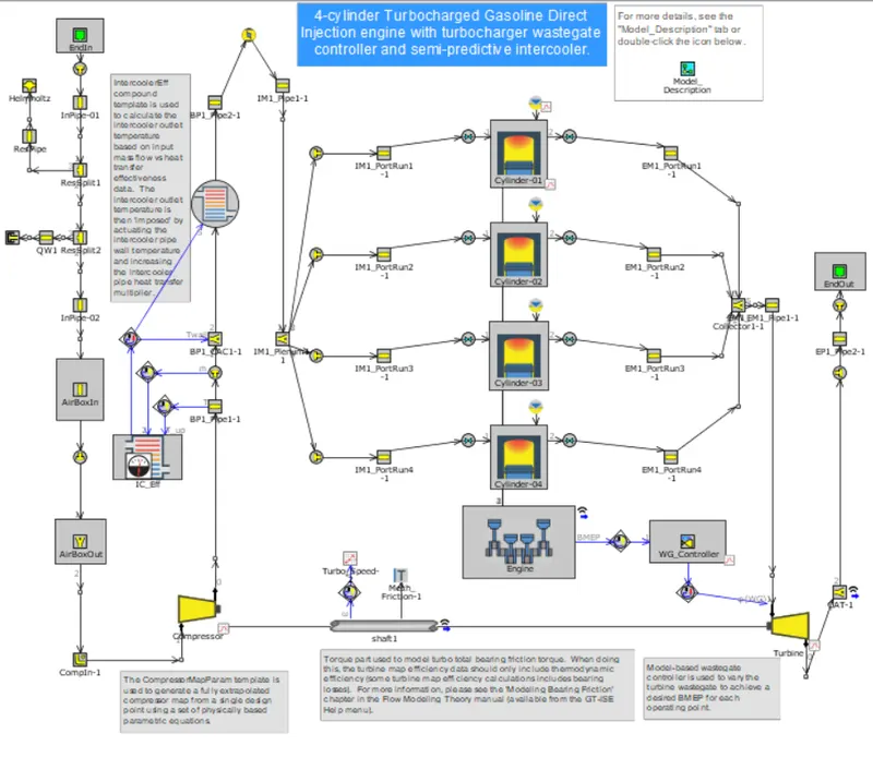
The compressor outlet pipes are reduced to a single volume by using the FRM convertor
STEP 5: INTAKE PIPES
The intake pipes are reduced in to a single model and transition from detailed to FRM model.
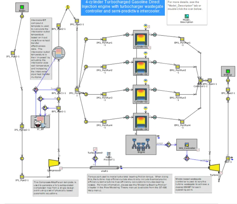
STEP 6: EXHAUST PORT
The exhaust parts are also gets simplified by combine flow wizard
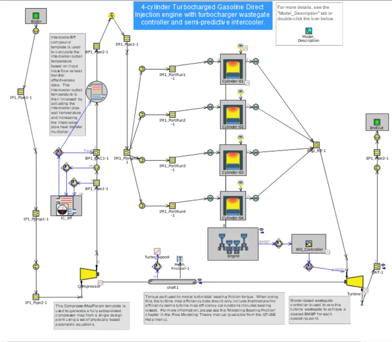
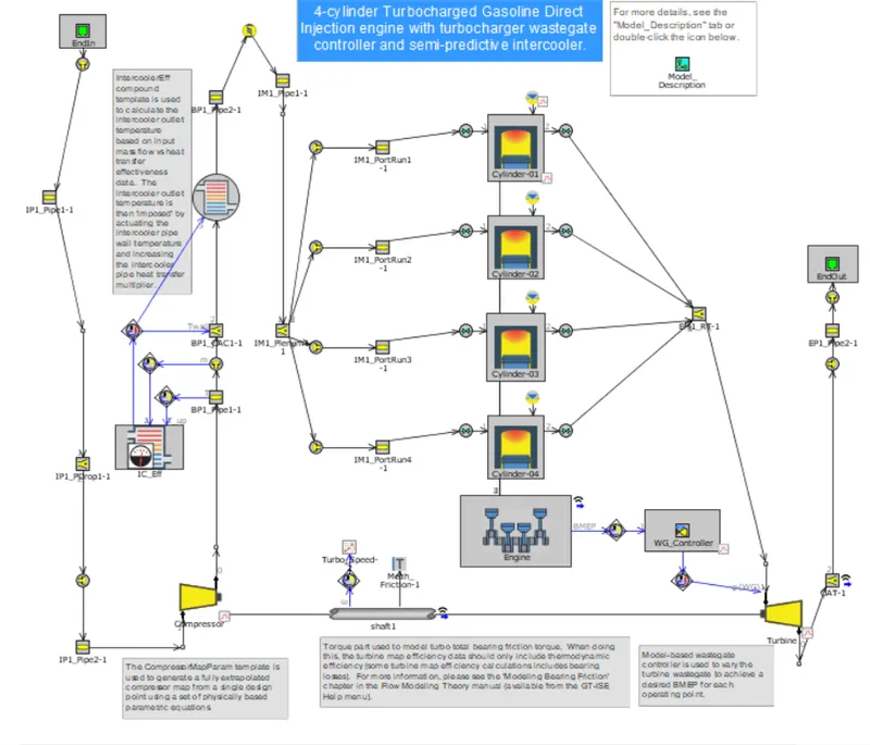
STEP 7: CYLINDER SLAVING
The final simplification to the model will utilize the Cylinder Slaving capability of the EngCylinder component.
The evaporation object was selected as cylEvap and the slaving option selected the slave type file which creates one cylinder as master and others follow the master thereby reducing the time in case of FRM.
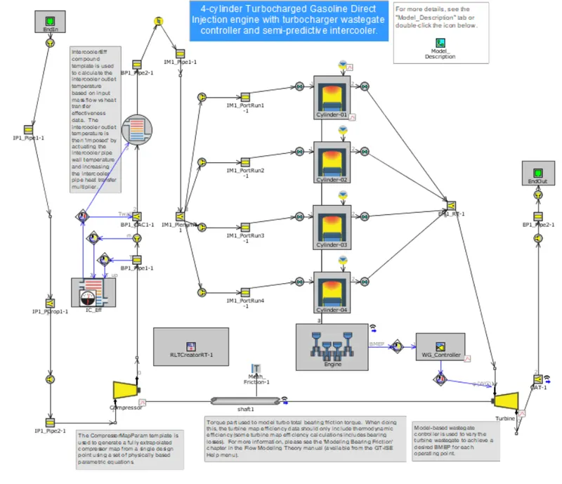
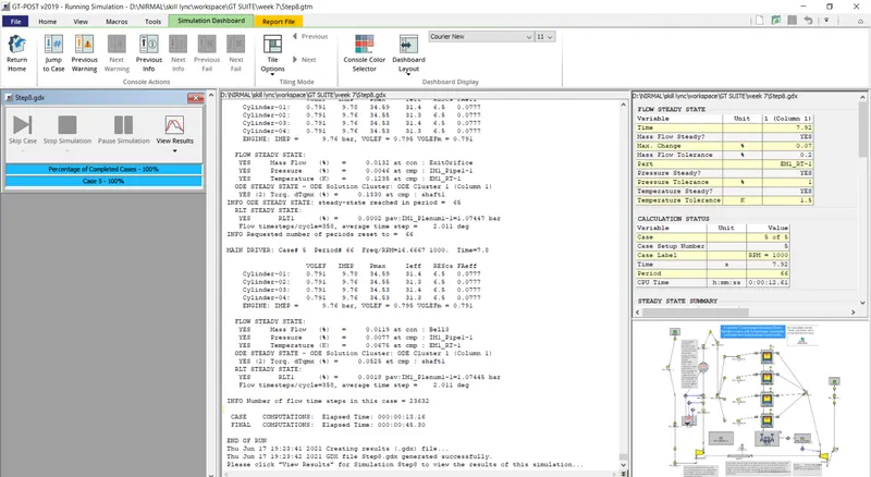
STEP 8: REAL TIME SOLVER
The RLT was setup and the license must be changed to GT suite to GT power to run the simulation.
RESULTS:
2. Build FRM Model for following configuration using FRM builder approach
- Bore 102 mm stroke 115 mm CR 17
- No of cylinder 6
- CI engine
- Twin Scroll Turbine
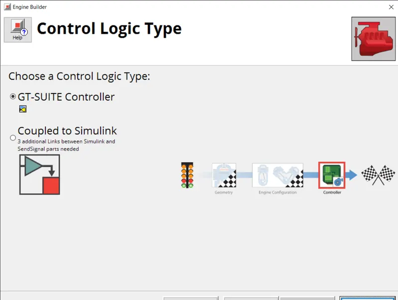
- GT Controller
FRM BUILDER APPROACH:
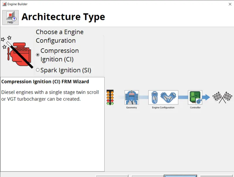
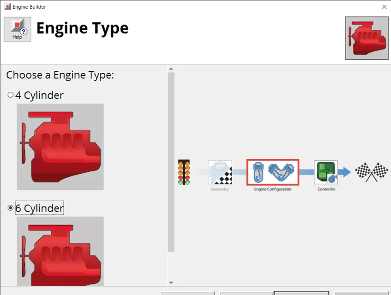
GT provides a feature called FRM builder, in which we need to give some information like architecture type, engine type, cylinder geometry, turbo type and controller logic type.
Steps for FRM builder is shown below,
ARCHITECTURE TYPE:
CYLINDER GEOMETRY:
TURBO TYPE:
ENGINE TYPE:
CONTROL LOGIC TYPE:
MODEL DESCRIPTION:
INTAKE:
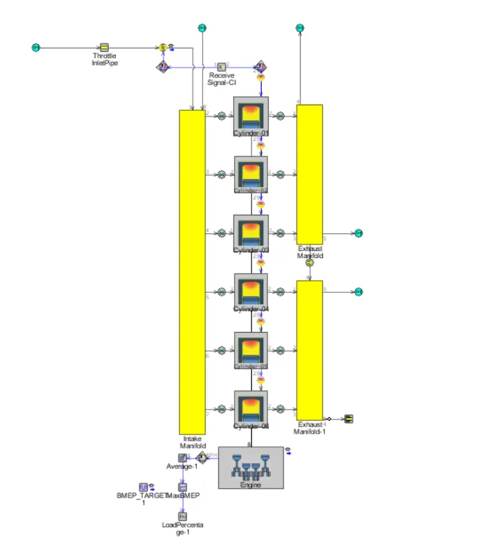
FRM DIESEL:
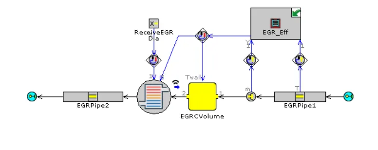
EGR:
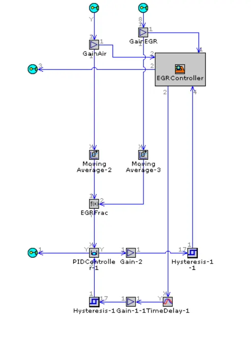
EGR CONTROL:
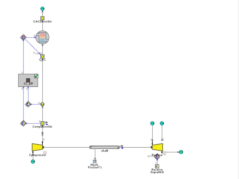
TURBO:
EXHAUST:

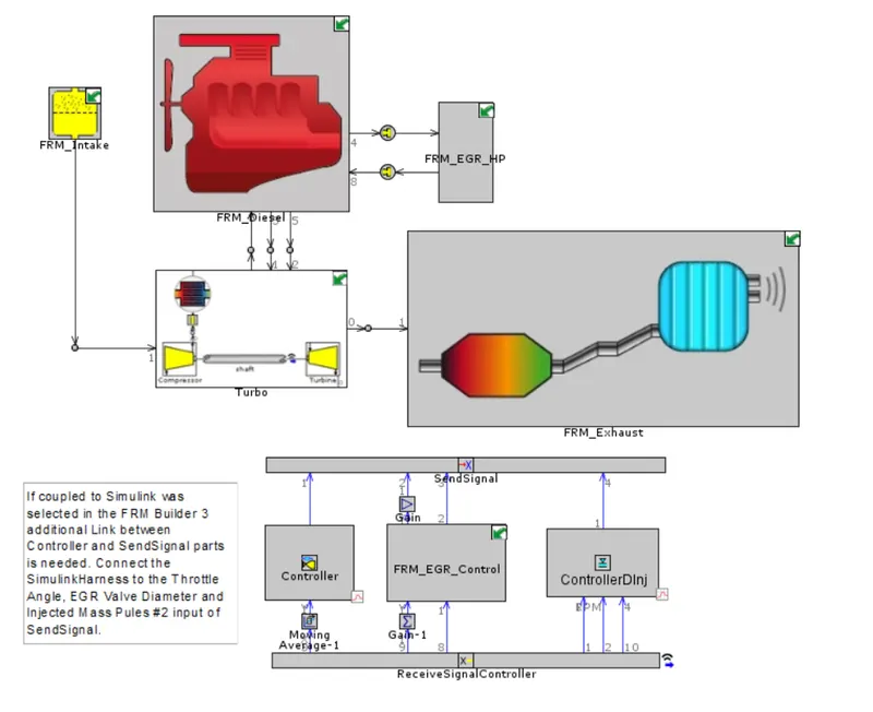
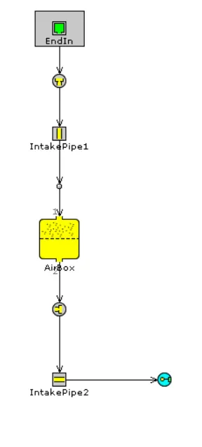
This is a 6 cylinder CI engine build with turbocharger, high pressure EGR and its controller. Since we use FRM approach, so the intake and exhaust are represented by single volume. A assembly is there to send and receive signals thus removing complexity.
CASE SETUP AND RESULTS:
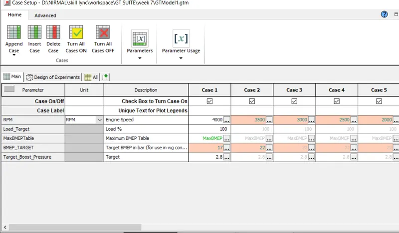
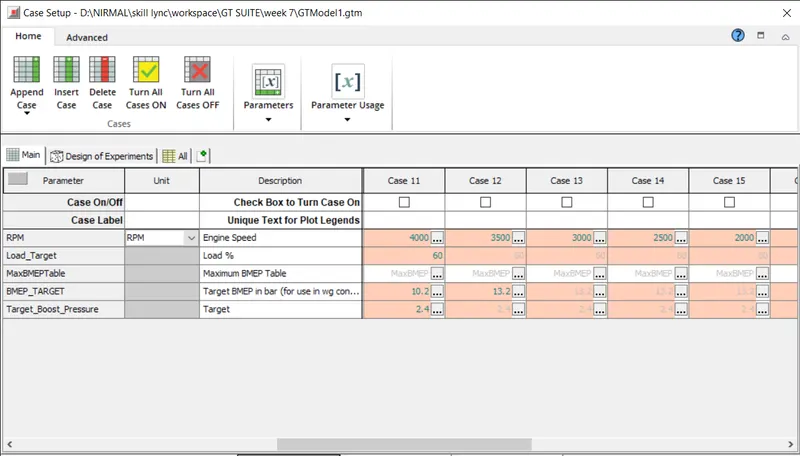
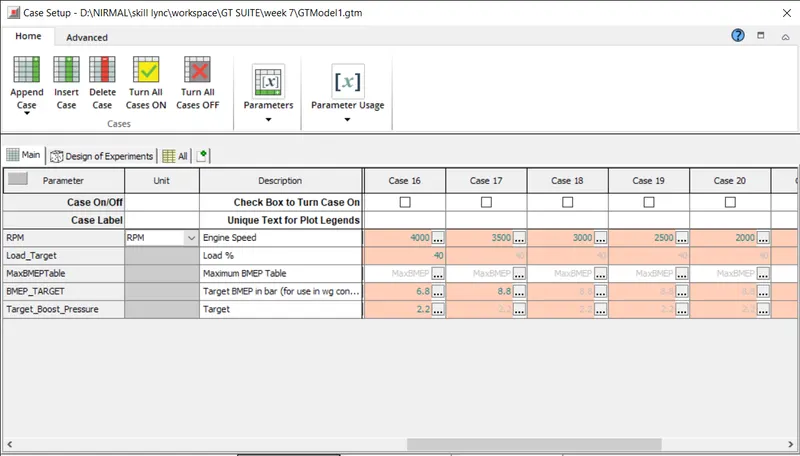
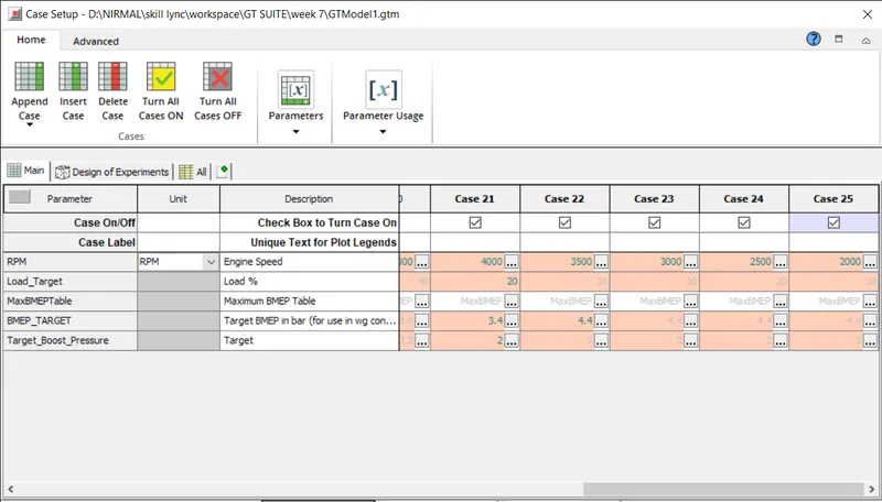
The simulation is ruuned for 25 cases with variation in RPM, target boost pressure, load target and BMEP target.
RUN TIME:
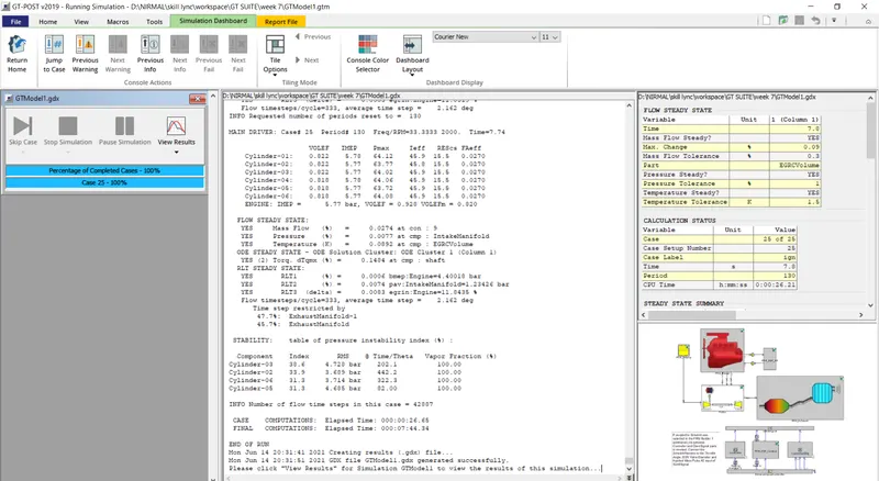
The above image shows the total run time of the 25 cases.
CASE 1-5:
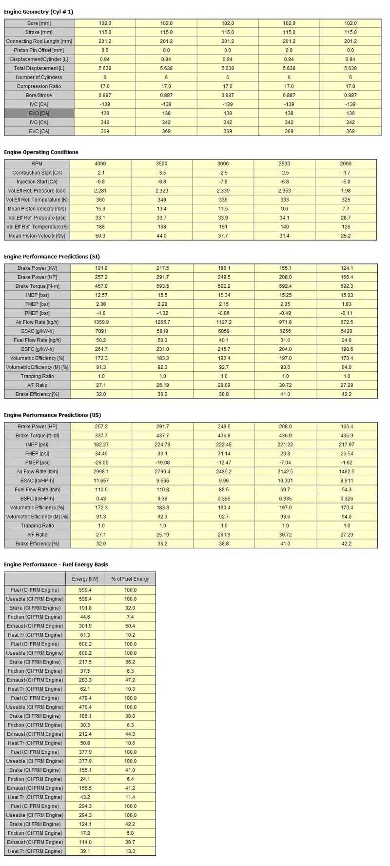
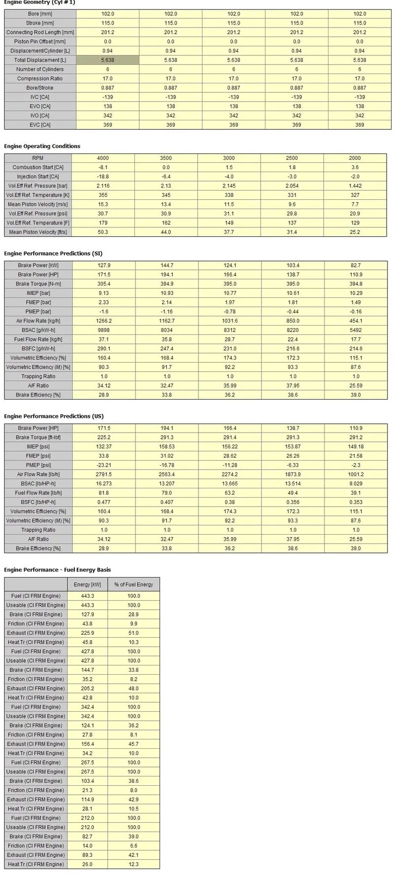
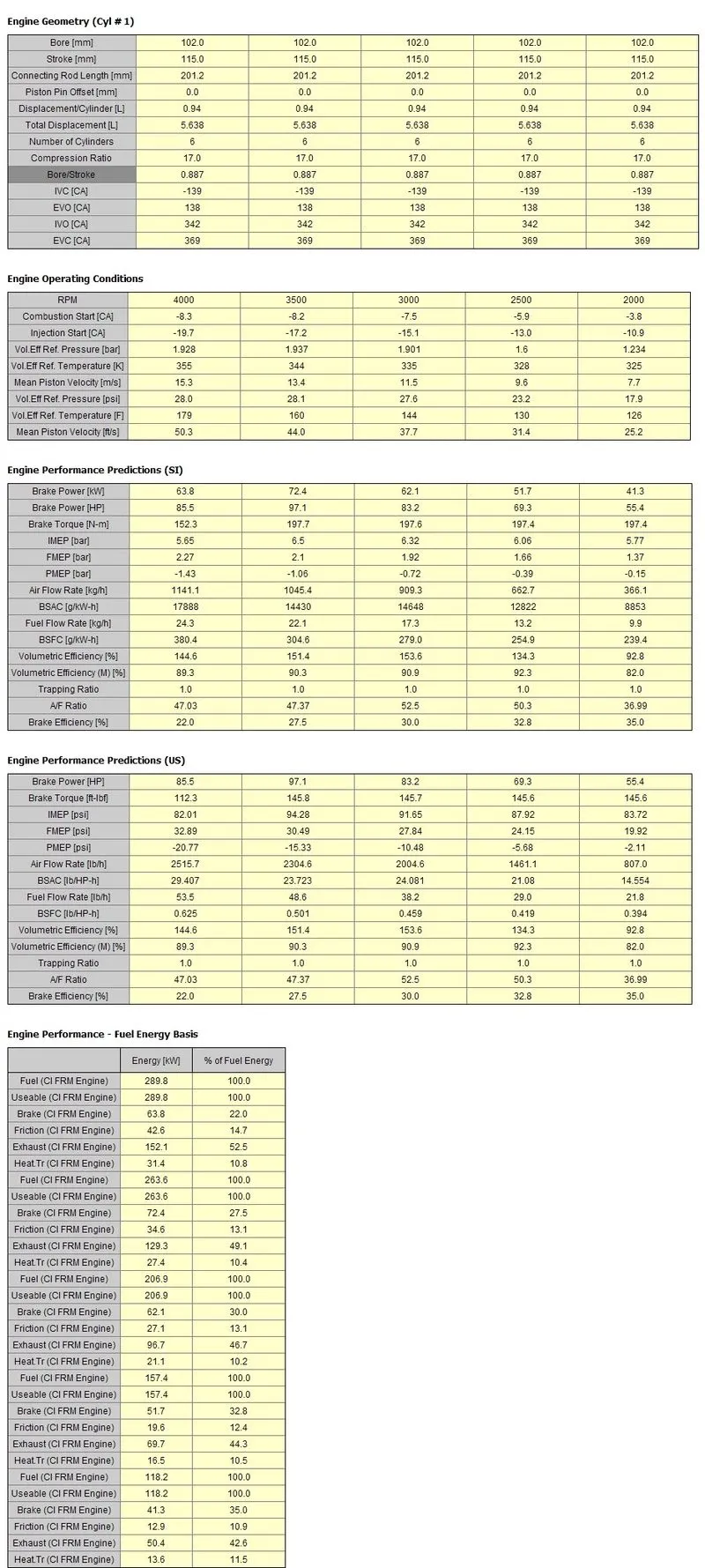
RESULT:


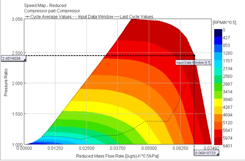
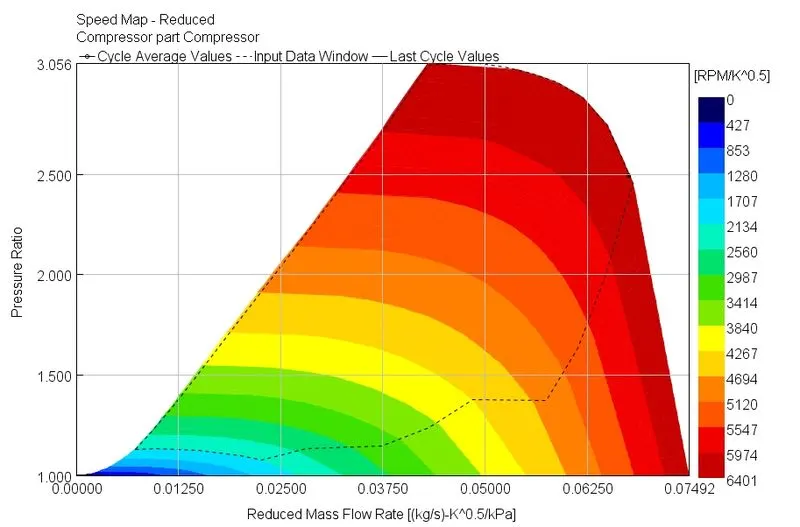
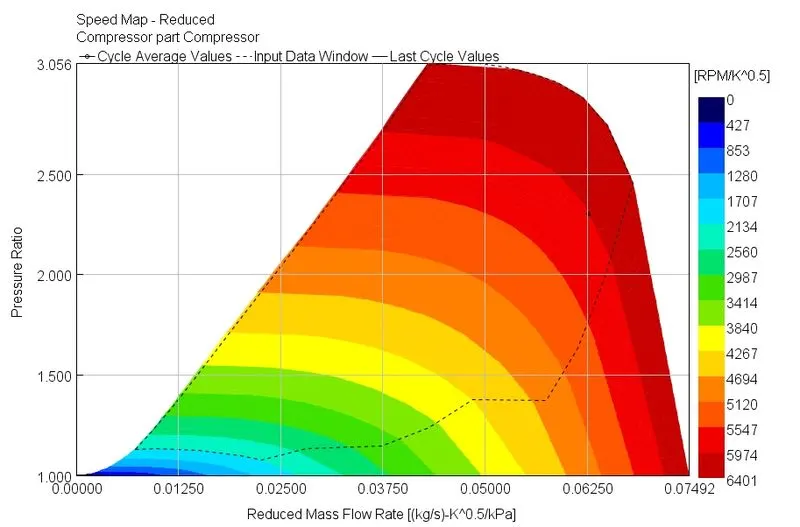
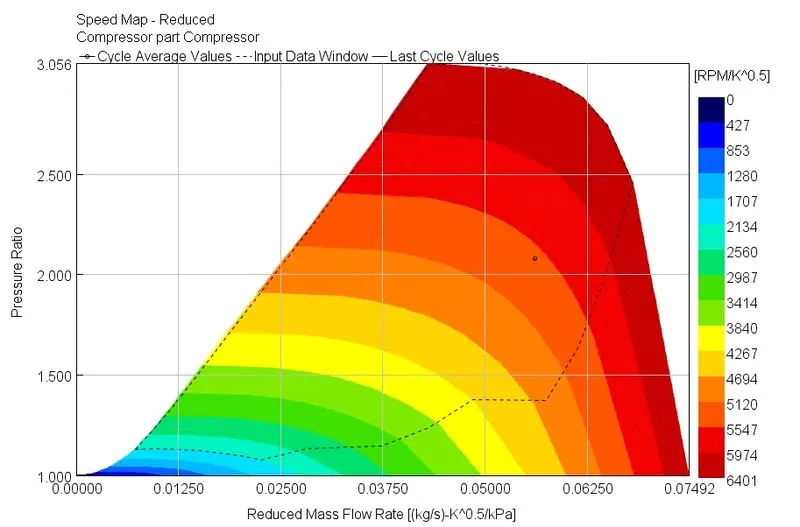
COMPRESSOR MAP:
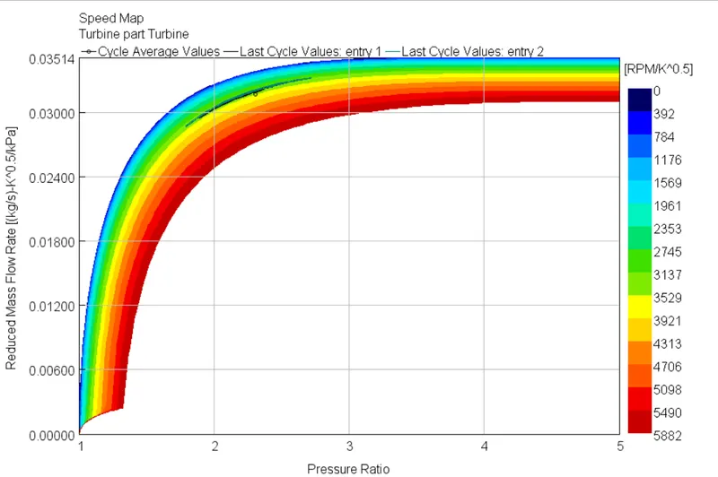
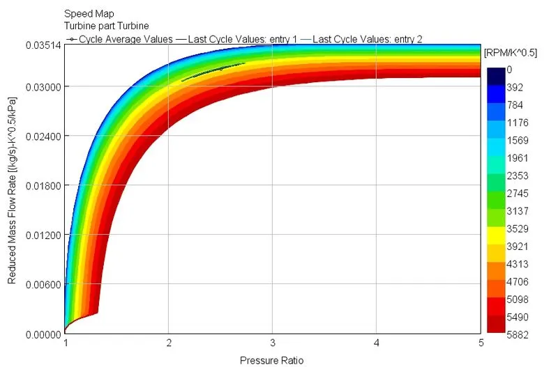
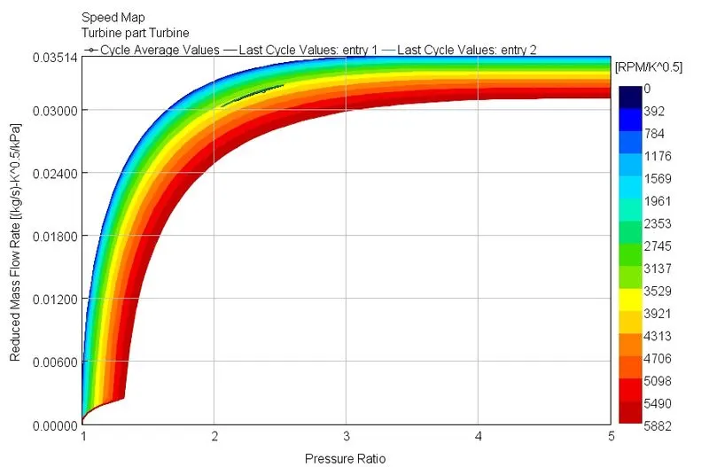
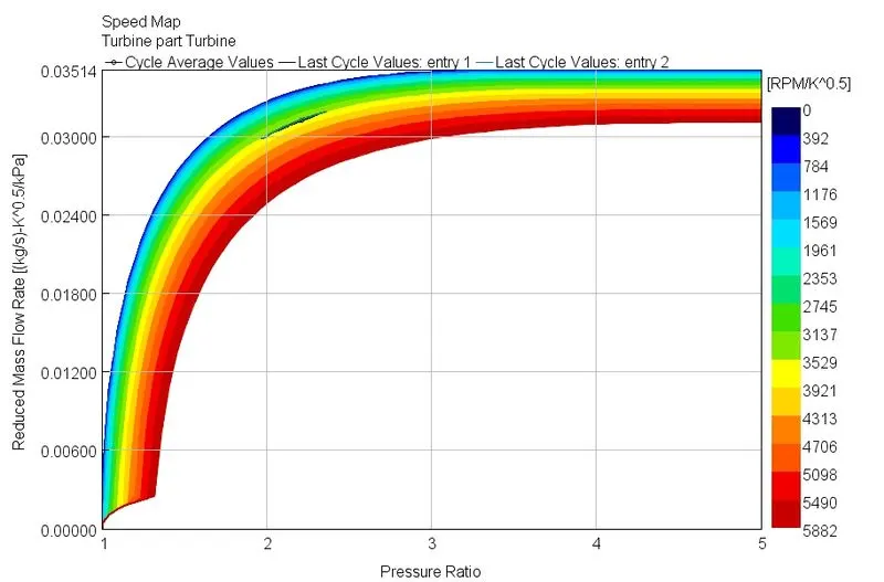
TURBINE MAP:
CASE 6-10:
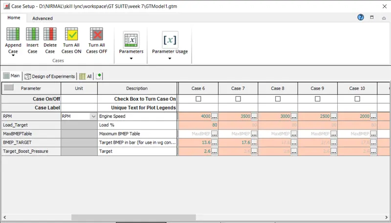
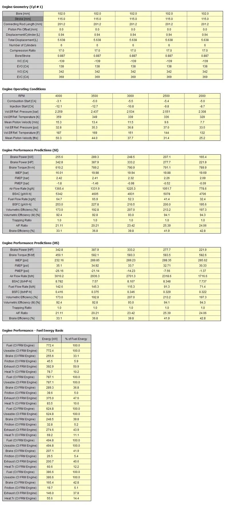
RESULT:

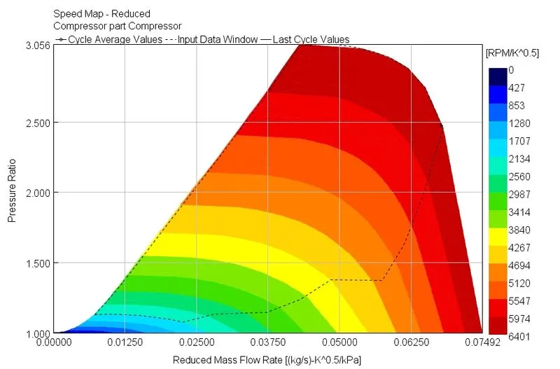
COMPRESSOR MAP:
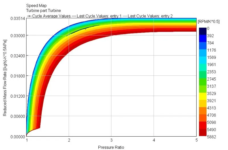
TURBINE MAP:
CASE 11-15:
RESULT:

COMPRESSOR MAP:
TURBINE MAP:
CASE 16-20:
RESULT:

COMPRESSOR MAP:
TURBINE MAP:
CASE 21-25:
RESULT:

COMPRESSOR MAP:
TURBINE MAP:
CONCLUSION:
- All cases were able to produce the target BMEP
- High-speed cases have higher BSFC values compared to low-speed cases.
- High-speed cases produces less power and torque compared to low speed cases.
- Compressors and turbine operates at critical speed in full load condition.
- FRM takes less time to converge than the detailed model.