Week-7 : Converting a detailed engine model to a FRM model
1.TUTORIAL 9:
MODEL: 4 CYLINDER GDI ENGINE. 4 STROKE, TURBOCHARGED ENGINE
FRM CONVERSION: To reduce the time period by converting from the detailed model to the fast-running model.
FRM CONVERTER :
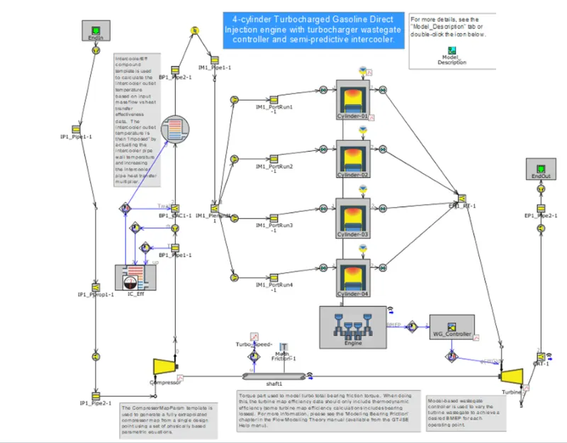
Total 8 steps are shown in the tutorial which reduces the high fidelity model which consumes more time to less time by taking the common volume or the parameters to reduce the number of steps for simulation. We can right-click and combine the parameters by given options.
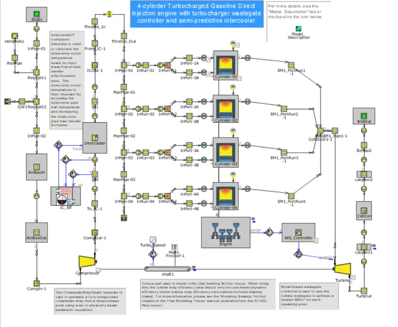
STEP 1: EXHAUST MANIFOLD
The exhaust manifold takes the common volume and combine the data in FRM conversion to reduce the steps in simulation and provide faster results.
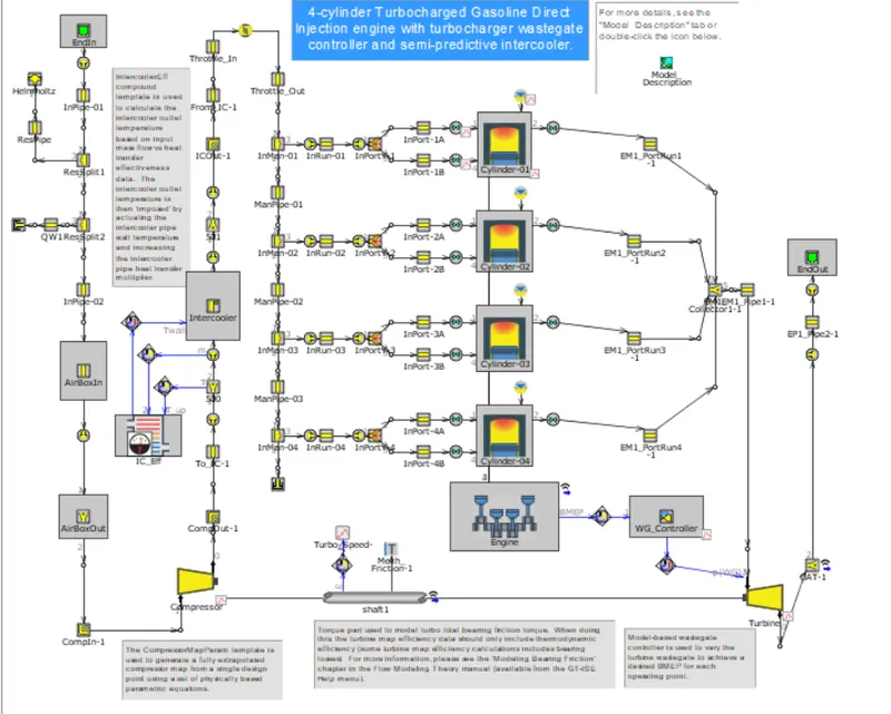
STEP 2: EXHAUST PIPES
The exhaust pipes connected to the turbine also reduces steps by FRM converter.
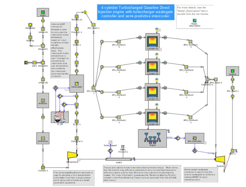
STEP 3: INTAKE MANIFOLD
The intake manifold simulates by taking one volume and reducing that particular section steps by eliminating more steps.
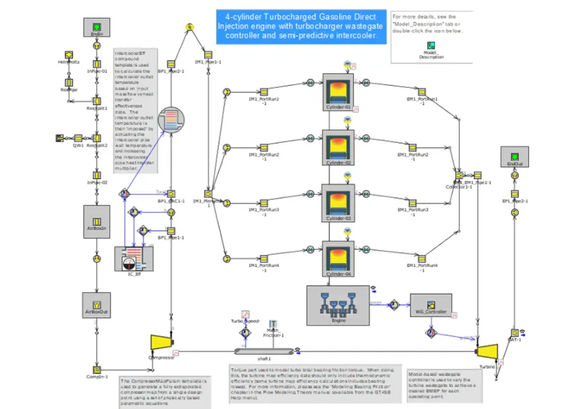
STEP 4: COMPRESSOR OUTLET PIPES
Similarly, the compressor outlet pipes passing to the intercooler also eliminates most of the steps by reducing into a common single model and transitions from detailed model to FRM model
STEP 5: INTAKE PIPE
the inlet pipes also follow the same principle and get simplified.
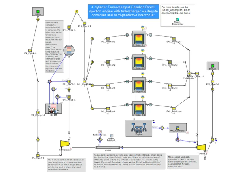
STEP 6: EXHAUST PORT
As one of the sixth step the exhaust port also gets simplified by combine flow wizard
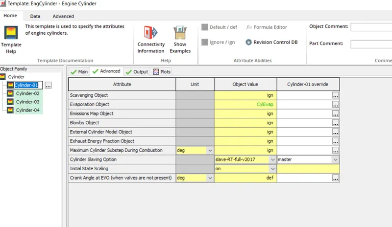
STEP 7: CYLINDER SLAVING
The evaporation object was selected as cylEvap and the slaving option selected the slave type file which creates one cylinder as master and others follow the master thereby reducing the time in case of FRM.
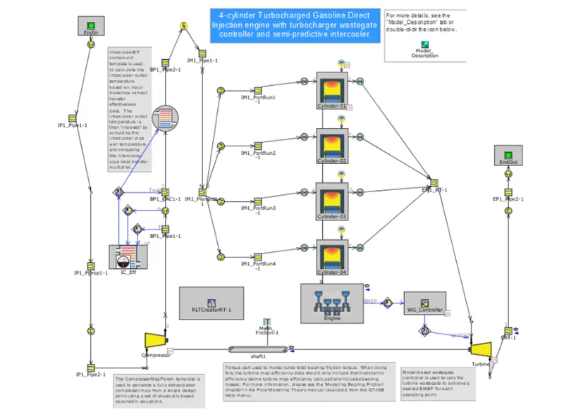
STEP 8: REAL-TIME SOLVER
The RLT creator was set up and the license must be changed to GT Suite from GT POWER RLT to run the simulation.
CASE SETUP:
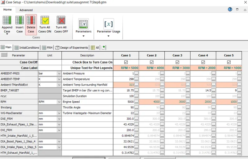
5 cases were run in simulation which had 100 cycles as simulation duration to simulate.
The target Bmep value was given to obtain results.
REAL-TIME FACTOR:
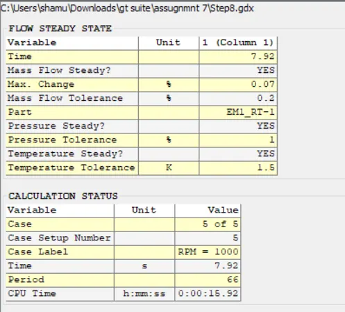
The real-time factor was around 2 as the CPU Time took twice as much as required by the actual duration to complete simulation by implementing FRM Model whereas without the FRM conversion it would be way higher than the value we obtained.
2. FRM BUILDER:
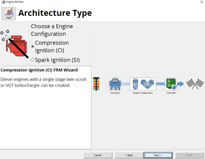
- To Build FRM Model for the following configuration using FRM builder approach
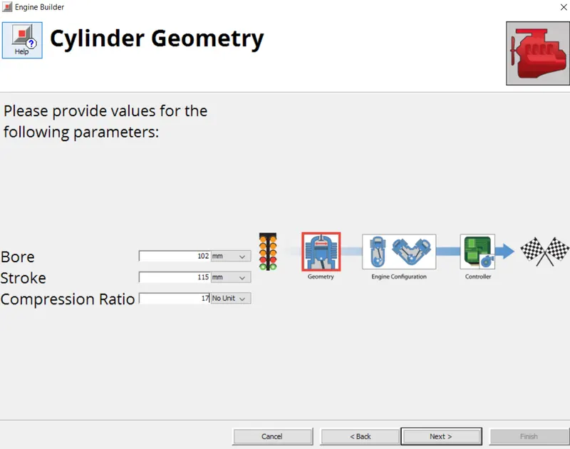
- Bore 102 mm stroke 115 mm CR 17
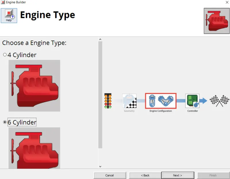
- No of cylinder 6
- CI engine
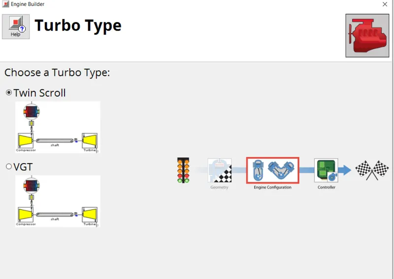
- Twin Scroll Turbine
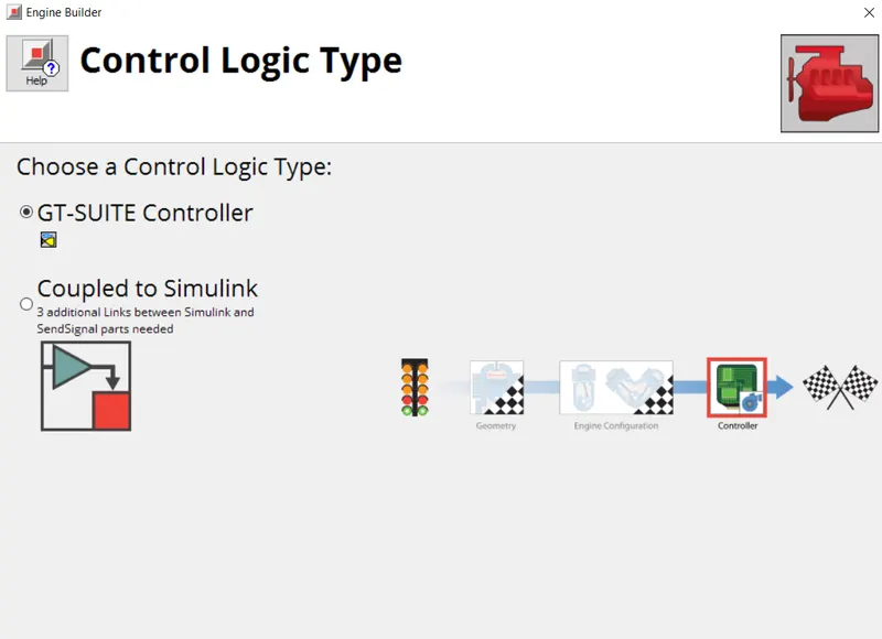
- GT Controller
CI ENGINE:
CYLINDER GEOMETRY
TWIN-SCROLL TYPE TURBO
6 CYLINDER ENGINE
GT CONTROLLER
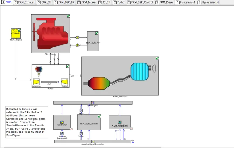
FRM BUILDER MODEL:
LAYOUT:
CASE SETUP:
25 Cases were setup and simulated accordingly.
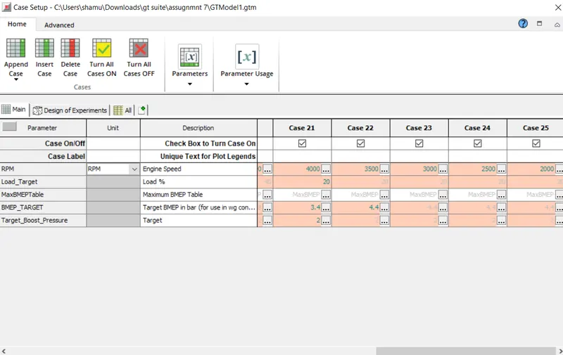
SIMULATION RESULTS:
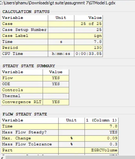
The CPU time was around 33.05 seconds whereas the time required was around 7 seconds. The real-time factor was found to be 4.8 approximately. All 25 cases were simulated and the CPU time varies with the device configuration also and therefore by the FRM builder model we could reduce the steps and achieve the fast-running model.
FEW PLOTS AND RESULTS FROM 25 CASES ARE SHOWN BELOW:
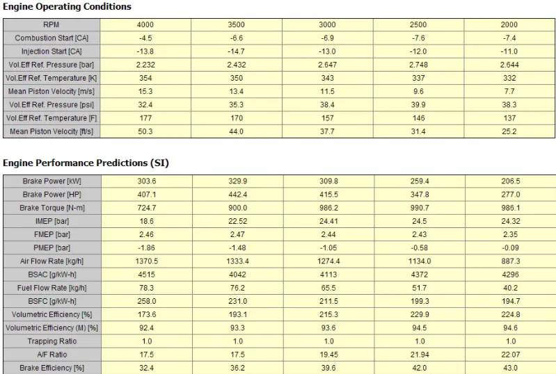
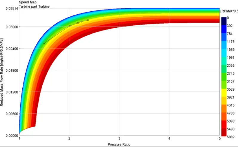
CASE 1 TO 5 RESULTS:

COMPRESSOR AND TURBINE MAPS:
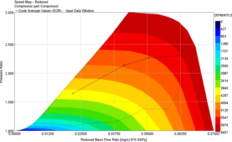
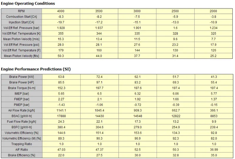
CASES 21 TO 25 RESULTS:

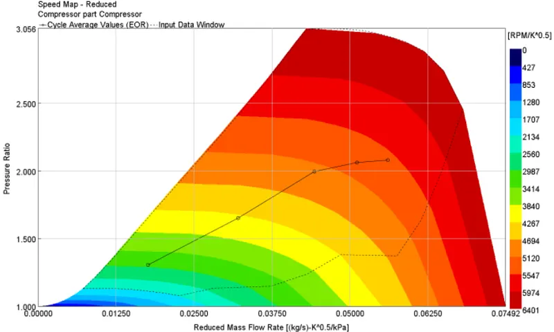
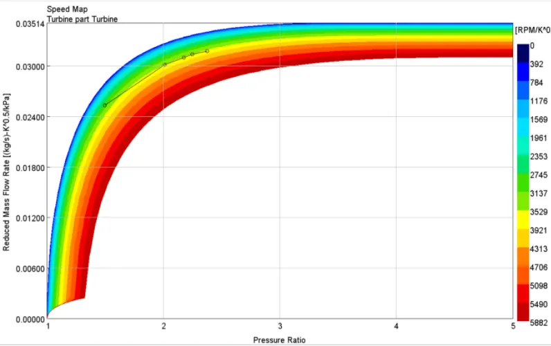
COMPRESSOR AND TURBINE MAPS:
CONCLUSION:
- Most of the cases almost achieved the target BMEP Value
- Higher load and BMEP leads turbine and compressor to operate at critical speeds
- The overall FRM model reduced the steps and gave faster results compared to the detailed model without FRM Builder.