Week-6 : Turbocharger Modelling
1. Different types of Turbochargers:
- Single turbo-charger
- Twin turbo-charger(sequential)
- Twin scroll turbocharger
- Variable Geometry turbocharger(VGT)
- Variable twin-scroll turbo-charger
- Electric turbocharger
- Wastegate turbocharger
Examples of turbochargers in GT POWER:
The snaps of the different examples are taken and shown below by grouping in CI and SI models from GT POWER:
CI MODELS:
1.
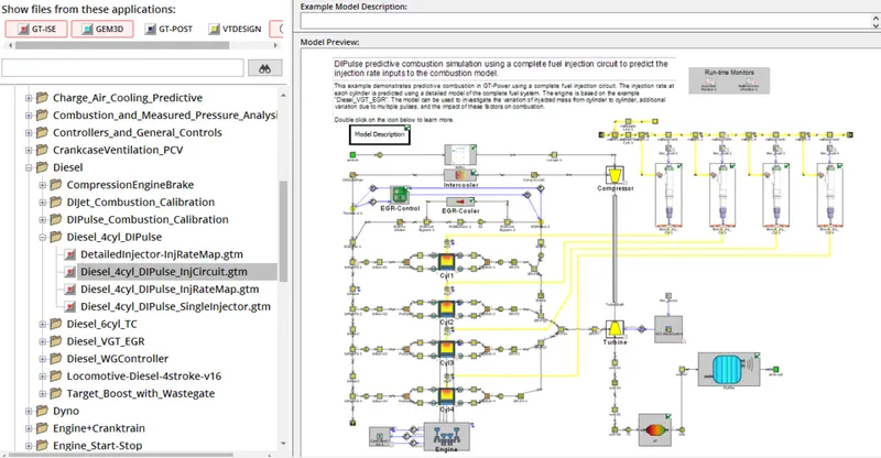
2.
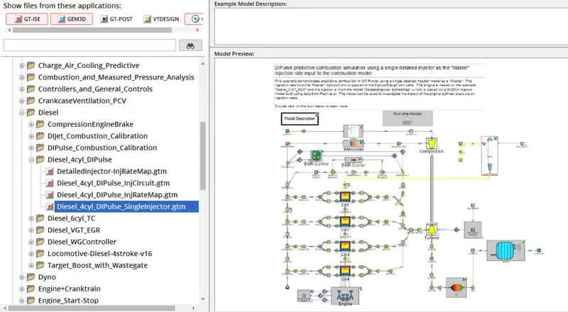
3.
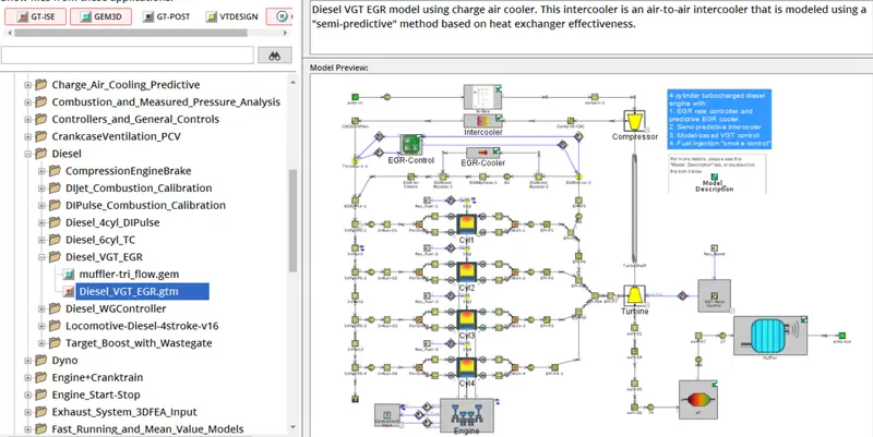
4.
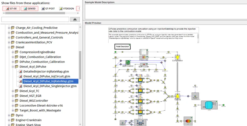
5.
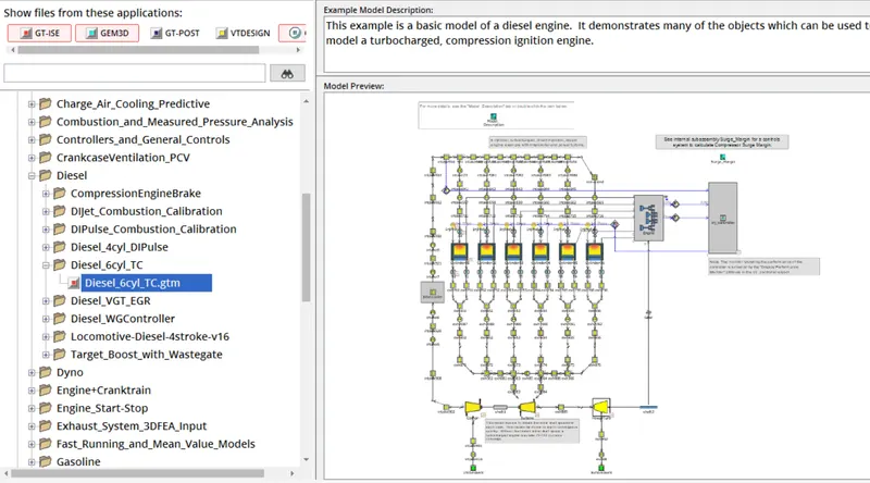
6.
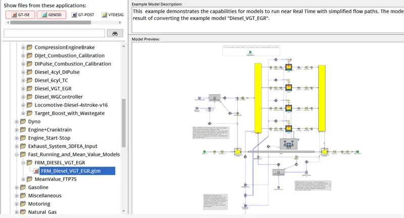
7.
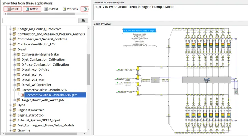
8.
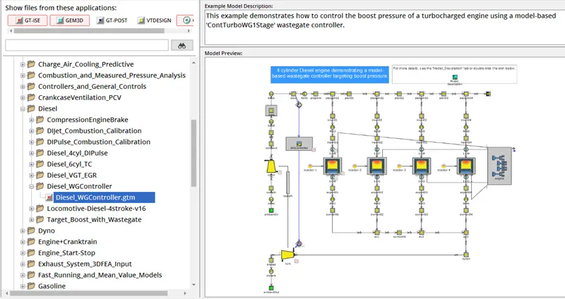
SI MODELS:
1.
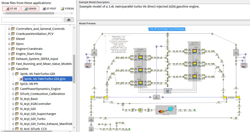
2.
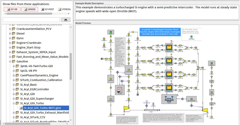
3.
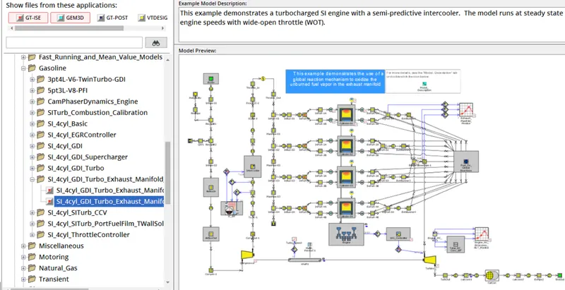
4.
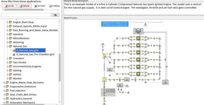
2. Exploring Tutorial 6 and 7
TUTORIAL 6
BRIEF SUMMARY:
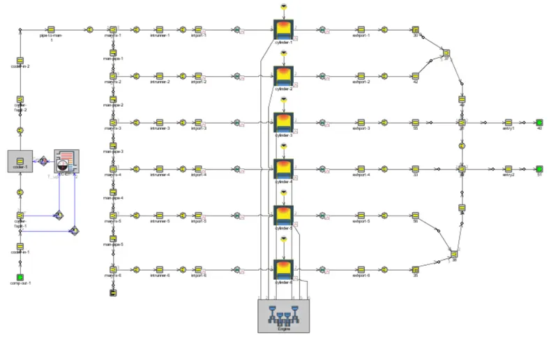
The 6 cylinder diesel engine with a direct fuel injection system is shown above which consist of an intercooler to cool the hot air by reducing the temperature of the compressor outlet gas which is later sent to the inlet manifold with high pressure but reduced temperature. The compressor and turbine inlets are given respectively.
TUTORIAL 7:
BREIF SUMMARY:
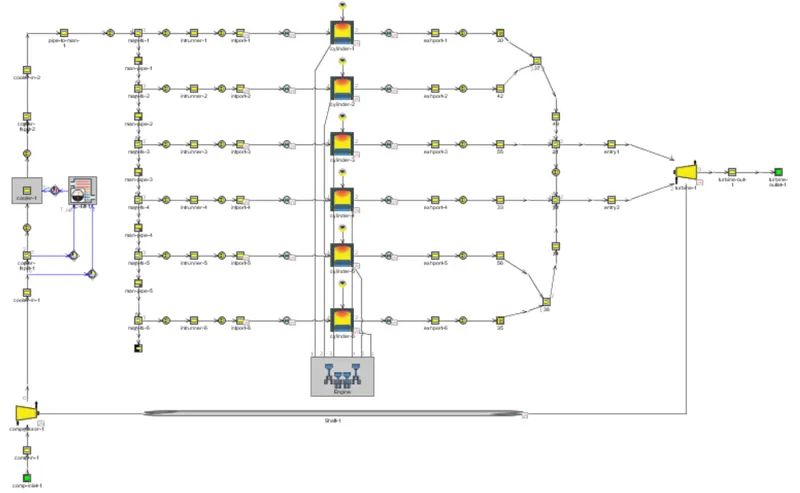
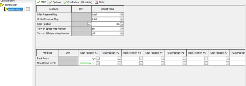
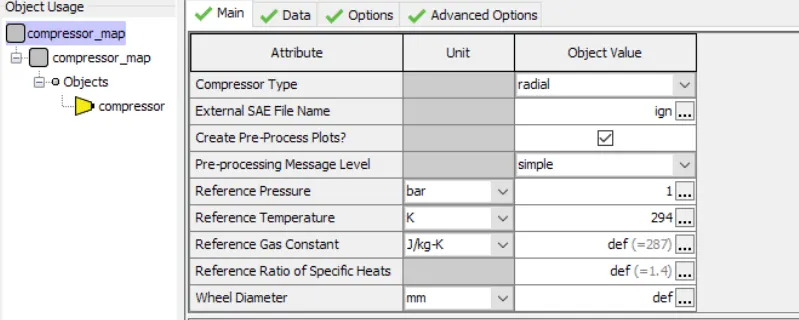
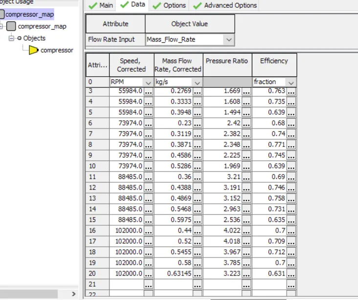
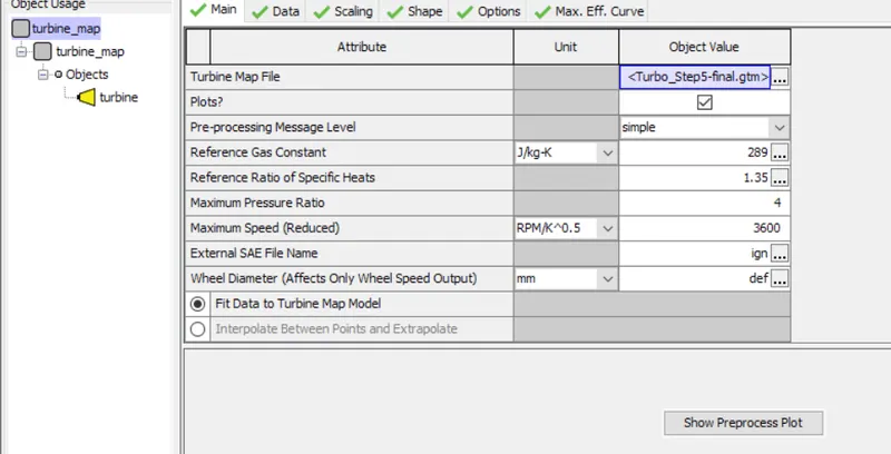
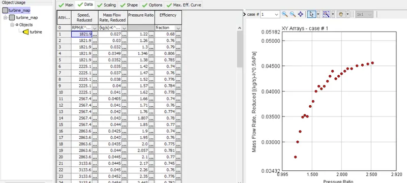
The compressor and turbine both are attached and coupled to each other where the compressor draws its power from the turbine which in turn runs on the exhaust gas flow. The twin-scroll turbine is used here which is connected at the exhaust of 6 cylinder diesel engine. The compressor and turbine maps with respective extensions are provided by the manufacturer's end and have been imported in data to run the simulation model in GT POWER.
3.
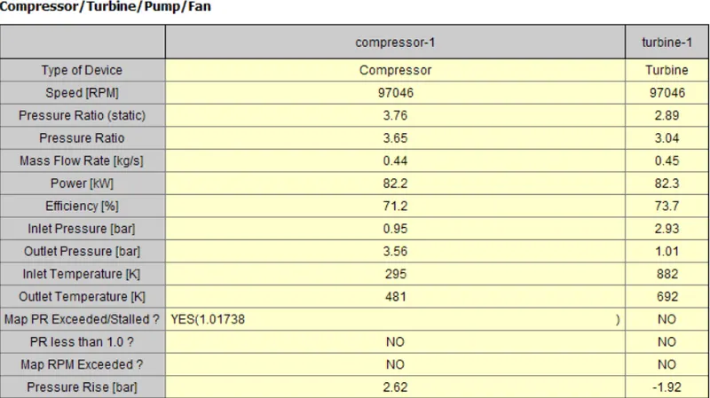
RESULTS OF TURBINE AND COMP VALUES TABLE:
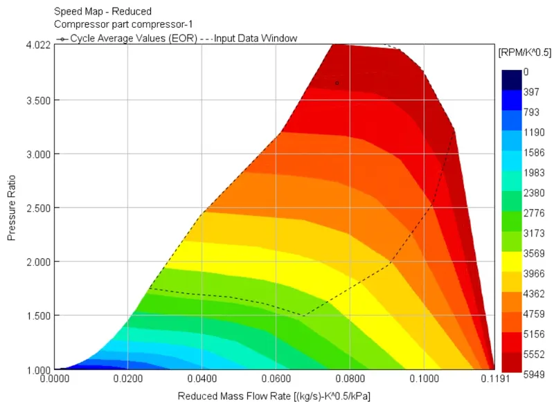
COMPRESSOR MAPS:
- COMPRESSOR SPEED MAP
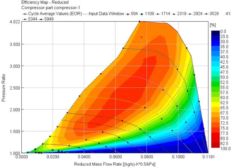
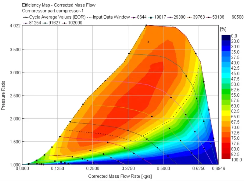
- COMPRESSOR EFFICIENCY MAP
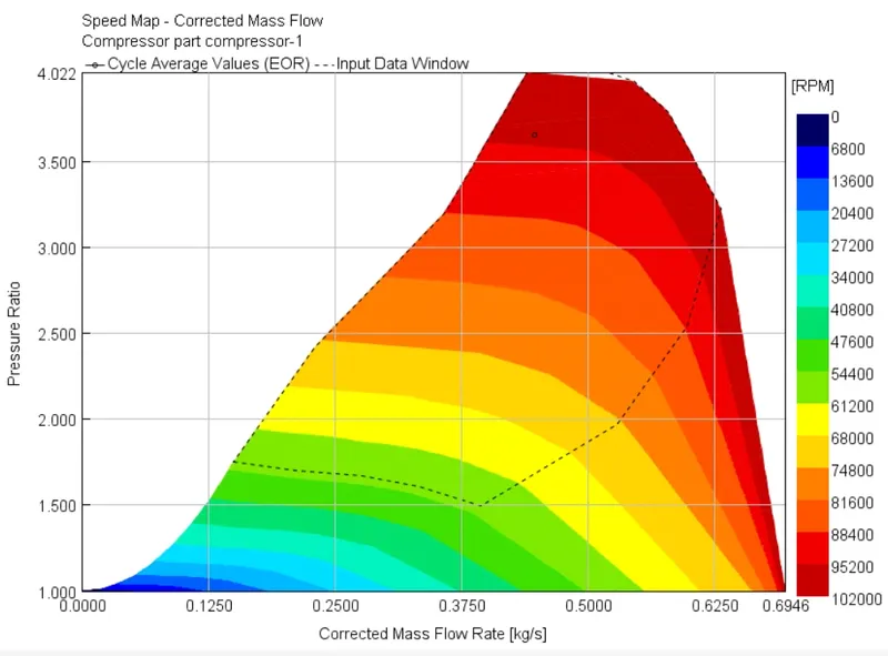
- COMPRESSOR SPEED - CORRECTED MASS FLOW RATE
- COMPRESSOR EFFICIENCY -CORRECTED MASS FLOW
TURBINE MAPS:
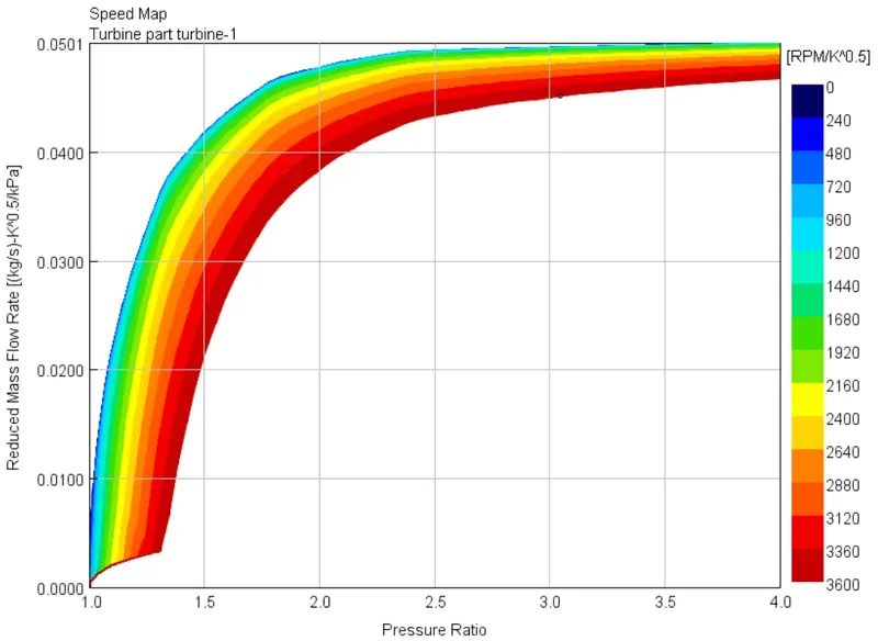
- TURBINE SPEED MAP
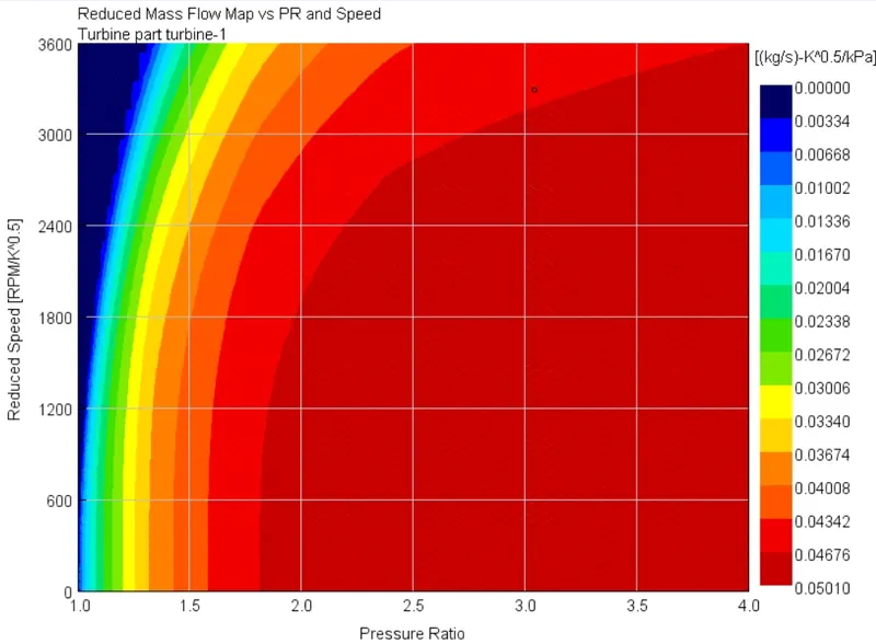
- TURBINE MASS FLOW MAP VS PRESSURE RATIO VS SPEED
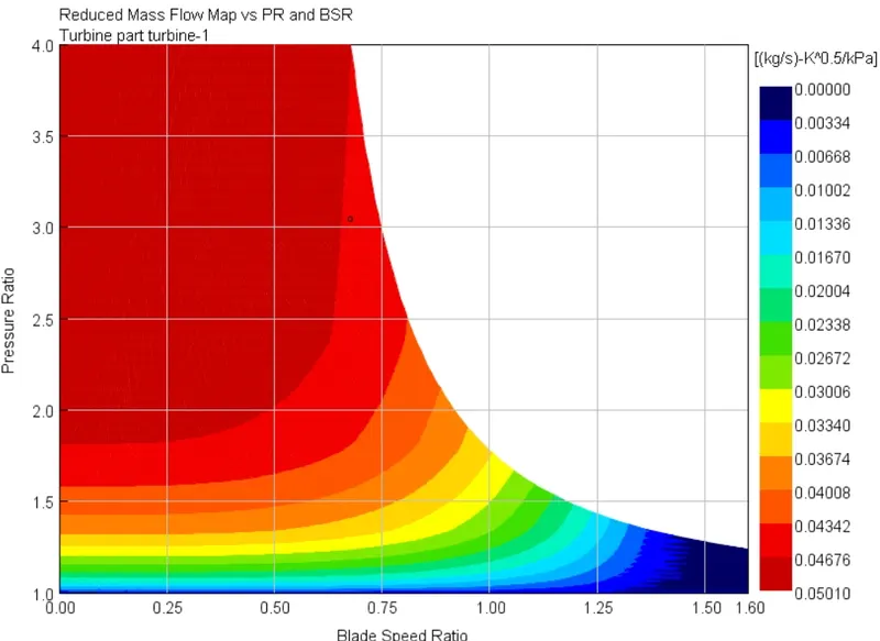
- TURBINE MASS FLOW MAP VS PRESSURE RATIO VS BLADE SPEED RATIO
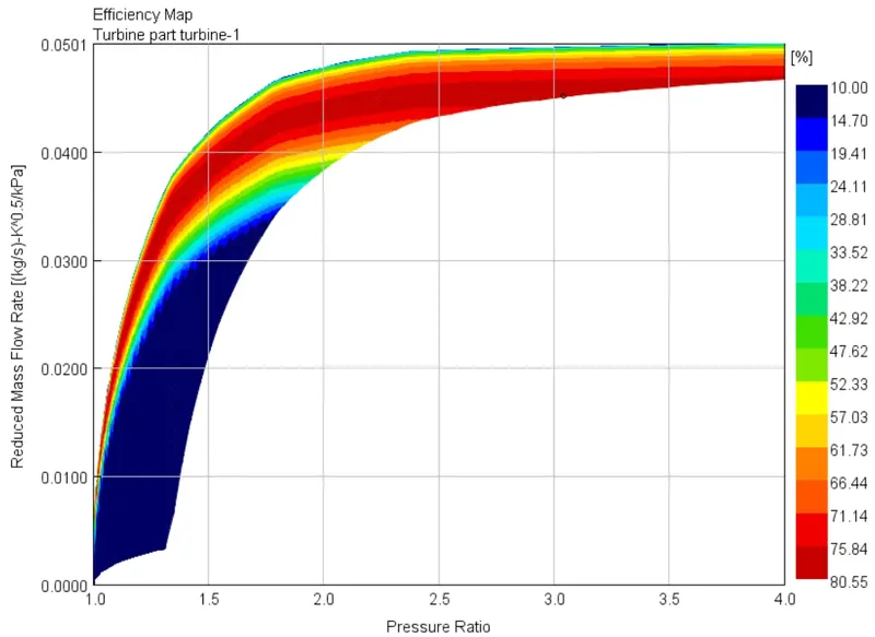
- TURBINE EFFICIENCY MAP
OBSERVATIONS:
operating points of compressor
- PR- PRESSURE RATIO = 3.65
- corrected mass flow = 0.446 kg/s
operating points of turbine
- PR- PRESSURE RATIO = 3.04
- Reduced mass flow = 0.076kg/s
- BSR-Blade speed ratio - 0.6758
4.
THE BENEFITS OF APPLICATION OF VGT OR VARIABLE GEOMETRY TURBINE IS AS BELOW:
At low engine speeds, the turbo lag is present which leads to poor performance especially in passenger cars that operate at low speeds in the city whereas on the highways they have good advantages due to high speeds.
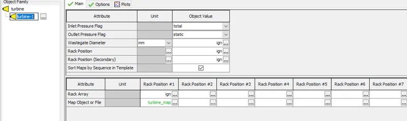
Therefore, the VGT was found to be very beneficial in Passenger cars that operate at both low and high engine speeds in order to achieve by making use of its application of variable geometries or rack array to obtain better performance and eliminate the turbo lag, unlike the fixed geometry turbines.
5.
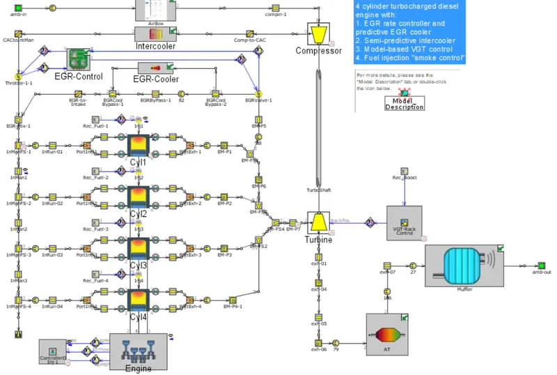
Exploring example of the Diesel VGT EGR and understand the modeling part
LAYOUT:
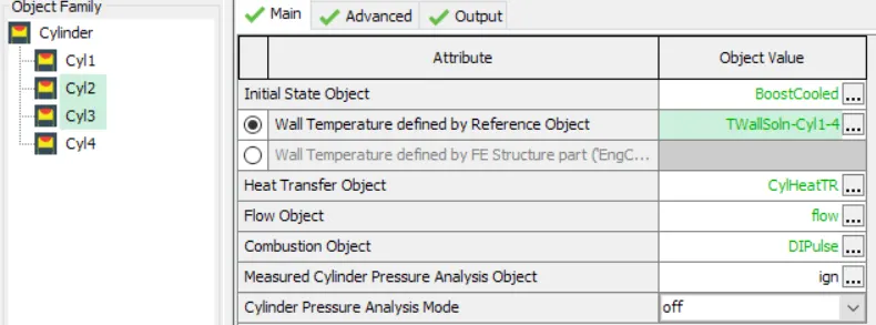
ENGINE CYLINDER:
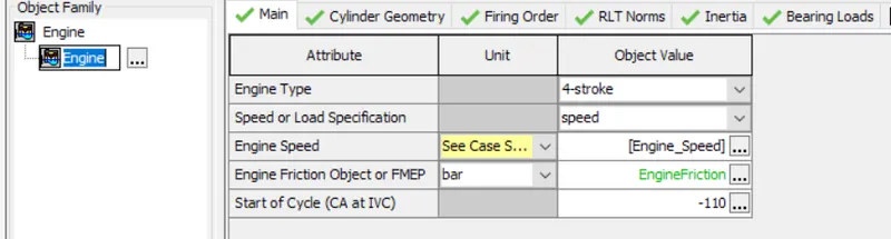
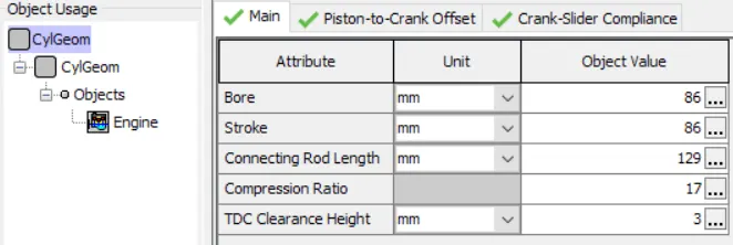
ENGINE GEOMETRY:
ENGINE CYLINDER:
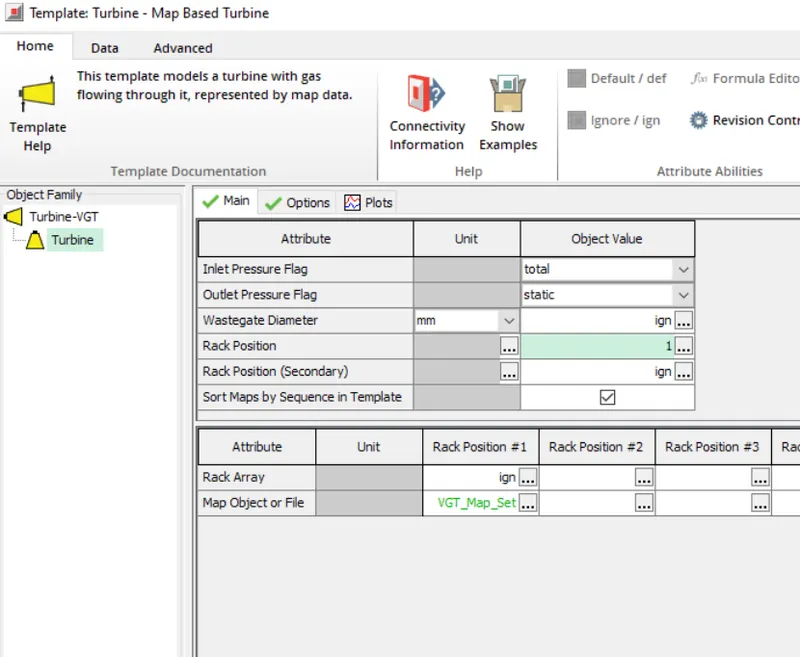
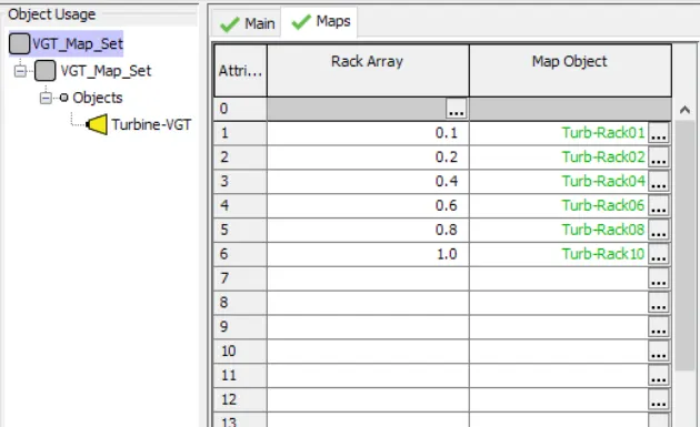
VGT MAP:
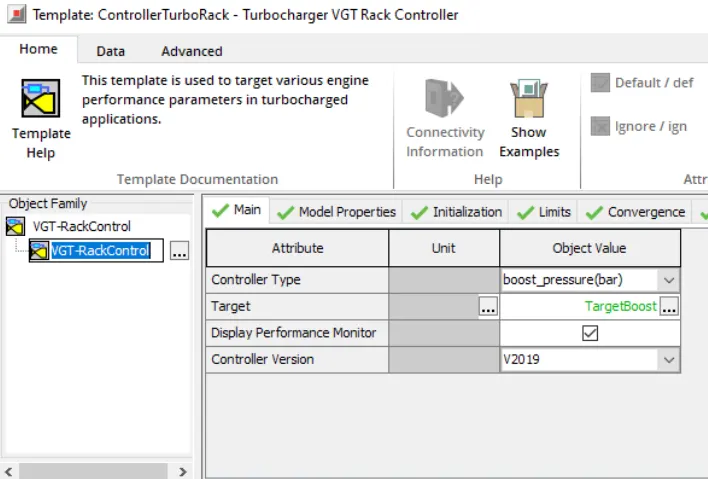
VGT RACK CONTROL:
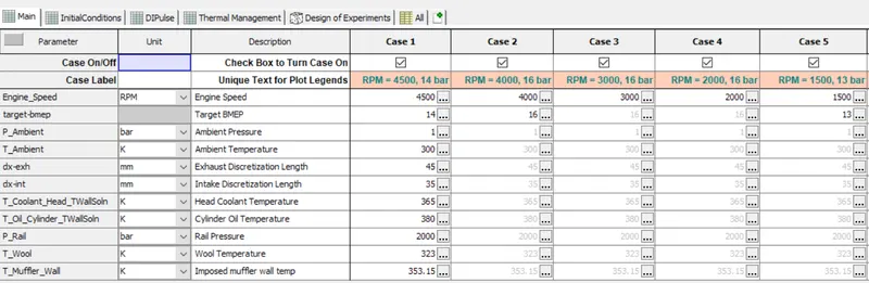
CASE SETUP:
RESULTS:
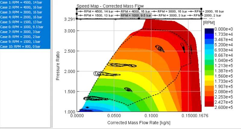
COMPRESSOR SPEED MAP -CORRECTED MASS FLOW RATE ALL CASES:
OBSERVATIONS:
At low engine speeds, we can observe that there is an increase in intake boost pressure. The engine speed decreases resulting in a reduction of pressure ratio and the output pressure overall.
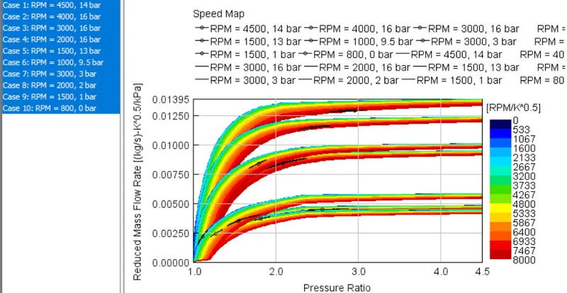
TURBINE SPEED MAP ALL CASES:
OBSERVATION:
The turbine map of pressure ratio vs the reduced mass flow rate was calculated in order to control the variable exhaust flow by varying rack position and making use of the VGT model in the above simulation for all cases.