Week 7 - CHT Analysis on a Graphics card
Objectives-
1. To perform CHT heat transfer steady state analysis on the graphic card model.
2. To find out the maximum temperature and heat transfer coefficient attained by the processor.
Introduction-
Conjugate Heat Transfer analysis is utilised for processes involving a wide range of temperatures in solids and fluids owing to thermal contact. The heating or cooling of a substance by the movement of air is a common example.
Heat transfer is the exchange of heat between two bodies, and the amount of the transfer of heat is directly proportional to the temperature differential between them. Heat transmission in solids is often accomplished by conduction, whereas heat transfer in fluids is accomplished through convection. The key to designing good coolers, heaters, or heat exchangers is efficiently mixing heat exchanges between solids and fluids. The most prevalent method for achieving increased heat transfers is forced convection.
The majority of applications combine heat transfers in solids with heat transfers in fluids. This is because fluid flows around solids or between solid barriers, and solids are often submerged in fluids.
For the analysis of temperature fields and heat transfer, an accurate description of factors such as material properties, flow regimes, geometric configurations, selecting right models depending on the physics to be represented, and heat transfer modes at the boundaries is required.
The following practical CHT issues are used to determine:
- The highest and lowest temperatures in various regions of the system. For example, combustion chambers, gas turbines, chemical tanks, and so forth.
- Temperature distribution is connected to thermal stress over a certain wall or system, for example.
- Temperature response in time-dependent applications such as heating/cooling problems (for example, cooling a specific system such as engine cooling)
- Coefficient of overall heat transmission.
SIMULATIONS:
In the initial section we will carry out simulation at baseline mesh with 1 m/s velocity at the inlet.
And in the later section we will carry out simulations at refined mesh with 1 m/s, 3 m/s and 5 m/s inlet velocities and compare their results.
Simulation Problem Setup-
1. First step was to complete meshing of the entire Graphic Card body.
2. Then setup tab in the standalone system is opened.
3. First we turned on the energy equation tab.
4. Secondly, K-epsilon turbulance model is chosen.
5. Then required materials were chosen from fluent database and if they are not available they were added with respective properties.
6. Proper solid and fluid regions were assinged along with the chosen materials to them. Information about materials is given in the next section.
Materials used-
| Part | Material | Density (kg/m^3) | Specific Heat J/(Kg.K) |
| Base | Titanium | 4850 | 544.25 |
| Fin Base | Copper | 8978 | 381 |
| Processor | Silicon | 2330 | 705 |
| Enclosure | Air | 1.225 | 1006.46 |
Section 1-
Baseline Mesh-
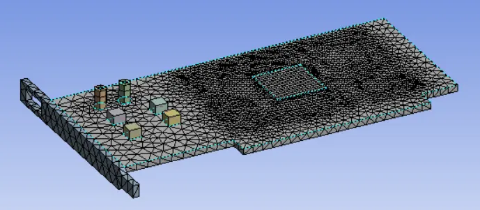
Meshing Information-
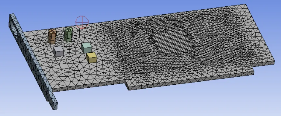
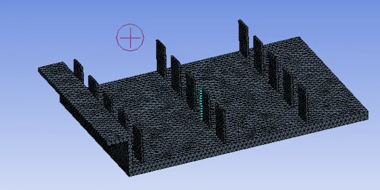
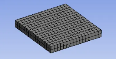
Entire body was meshed using three body sizing options.
Mesh size - 3 mm.
Body Sizing-
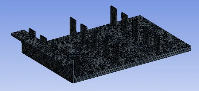
Base- 2 mm.
Fin Base- 1 mm.
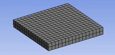
Processor- 1 mm.
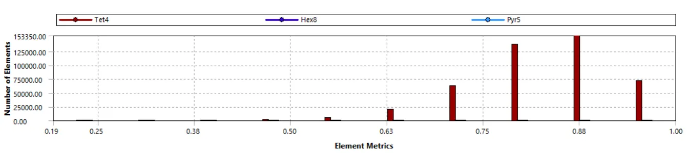
Element Quality mesh matric-

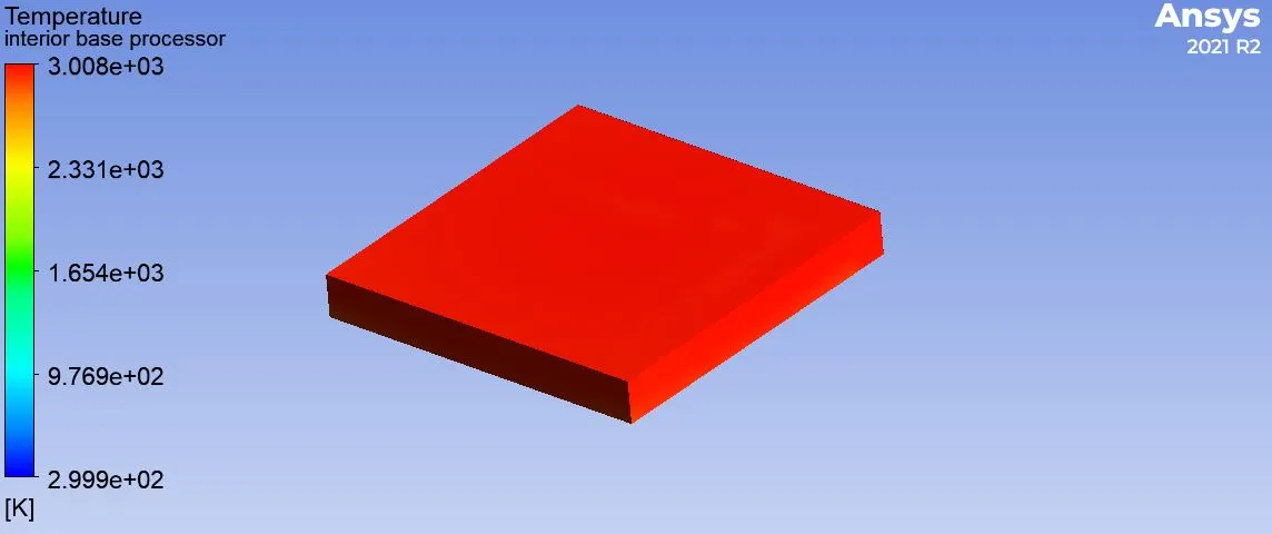
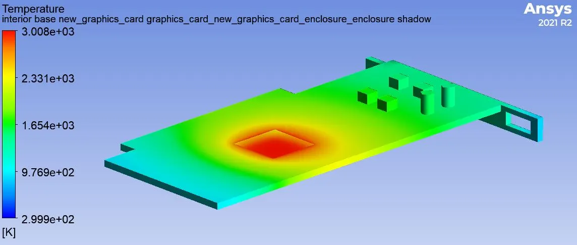
Processor Temperature-
Base Surface Temperature-
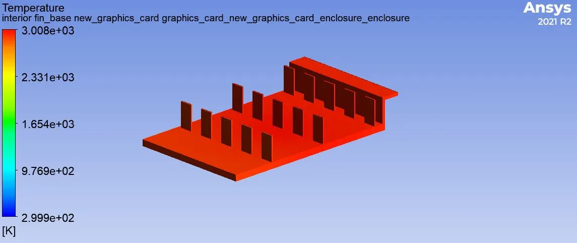
Fin Base Surface Temperature-
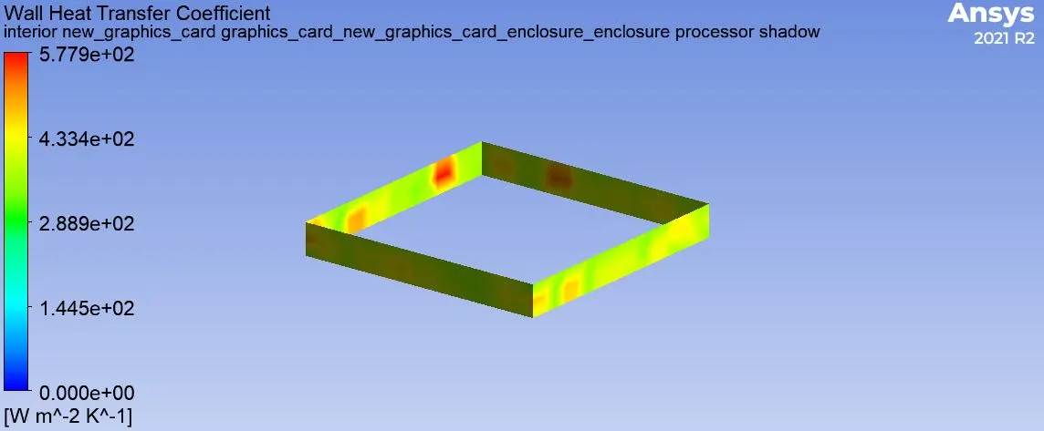
Processor Heat transfer Coefficient-
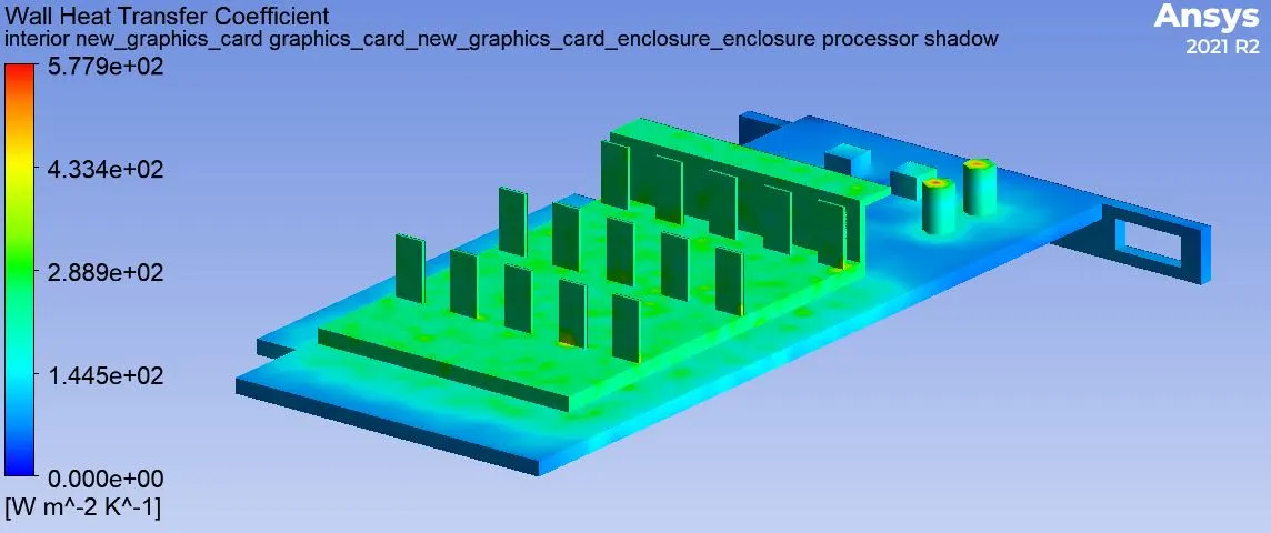
Wall Heat Transfer Coefficient of Graphic Card-
Section 2-
Refined Mesh Information-
Mesh - 3 mm.
Body Sizing-
Base - 2 mm.
Fin Base - 0.5 mm.
Processor - 0.5 mm.
Element Quality Mesh Matrix-
1 m/s Inlet velocity-
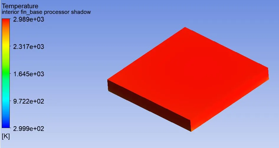
Processor Temperature-
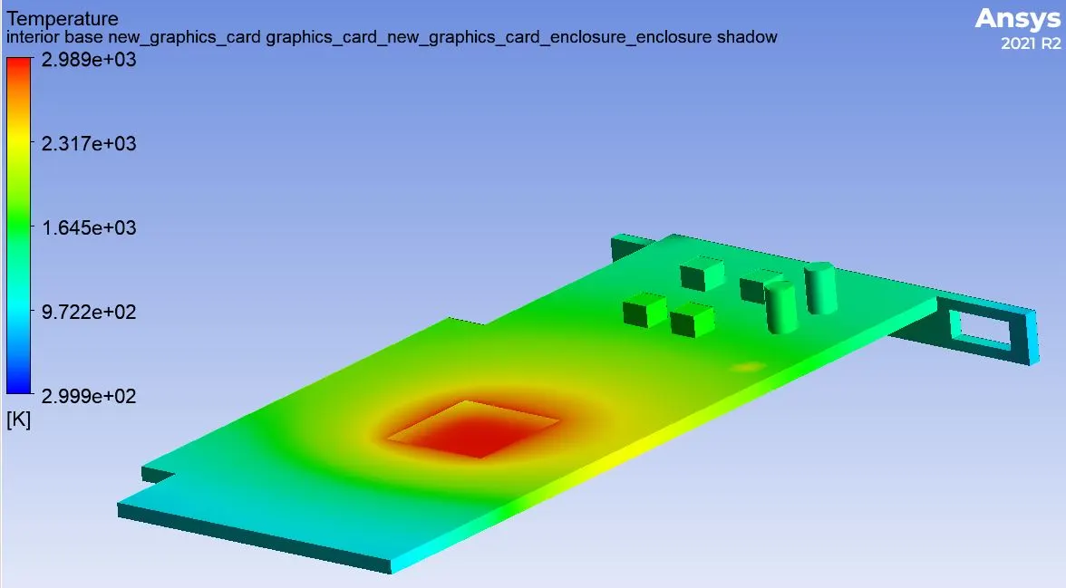
Base Surface Temperature-
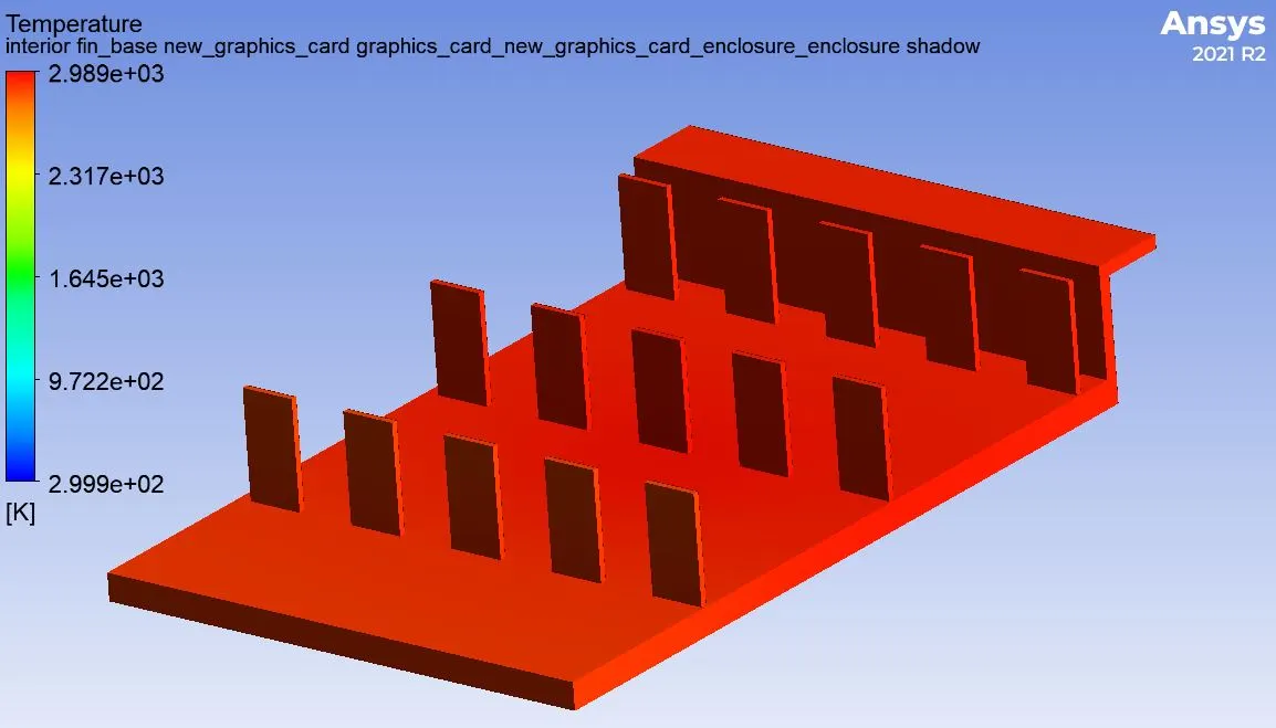
Fin Surface Temperature-
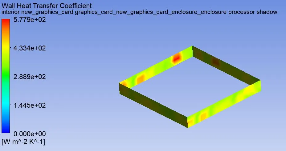
Processor Heat transfer Coefficient-
Graphic Card Heat Transfer Coefficient-
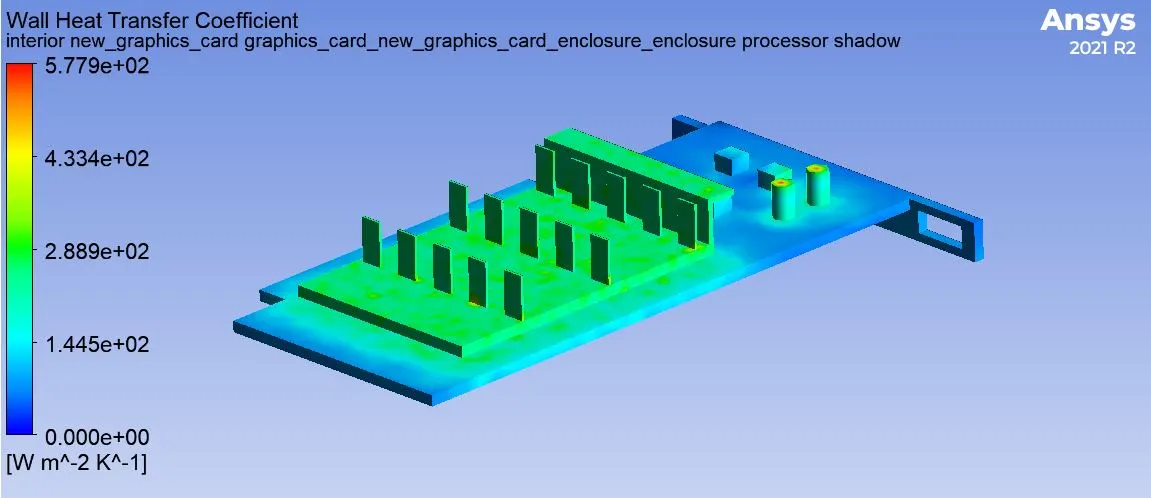
3 m/s Inlet velocity-
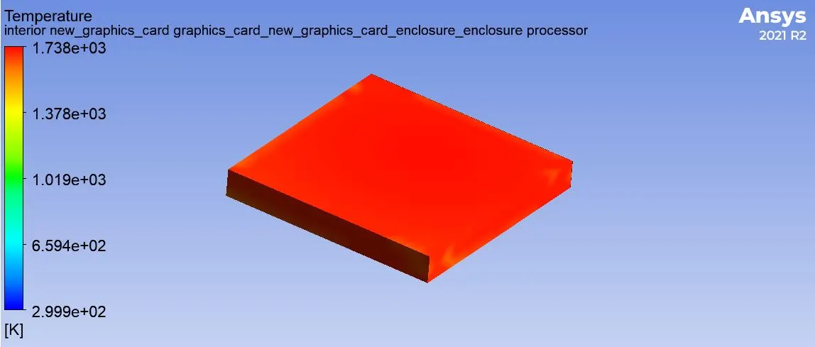
Processor Temperature-
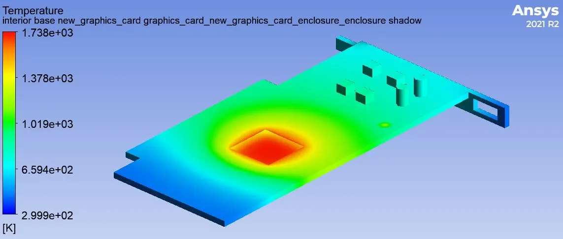
Base Surface Temperature-
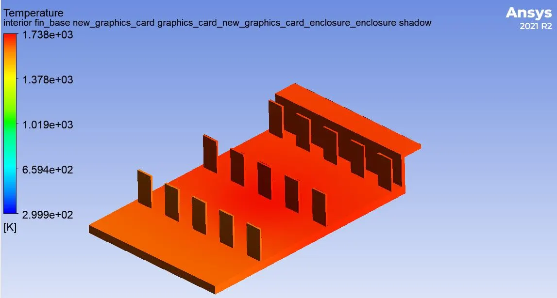
Fin Base Surface Temperature-
Processor Heat transfer Coefficient-
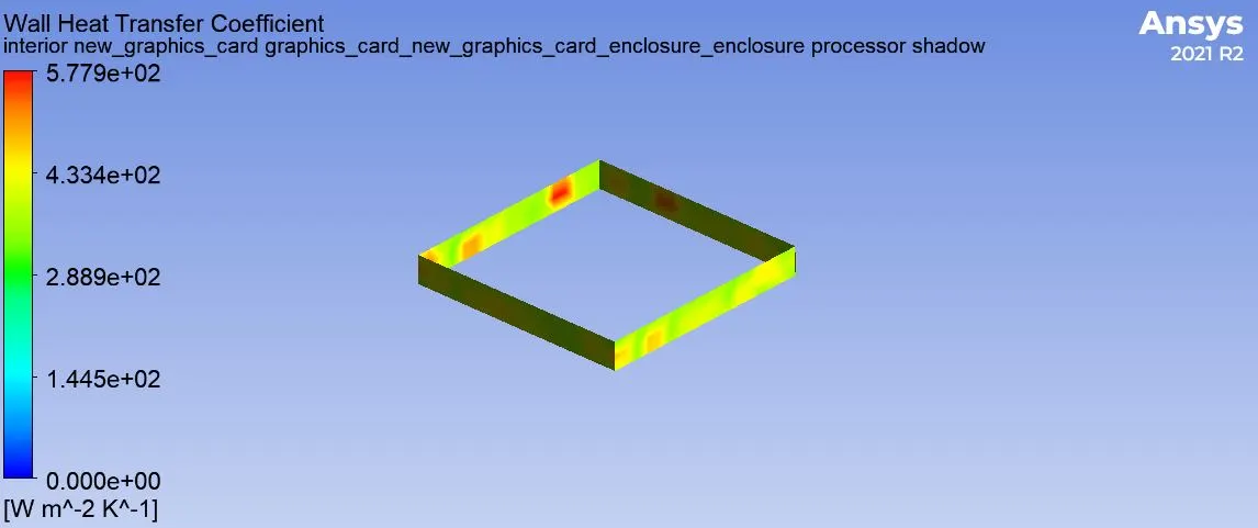
Graphic Card Wall Heat Transfer Coefficient-
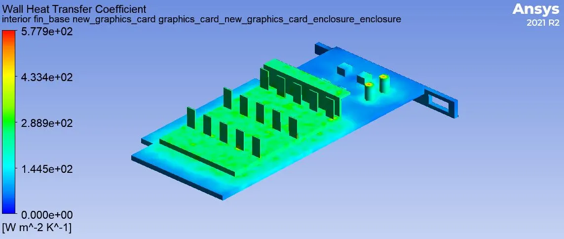
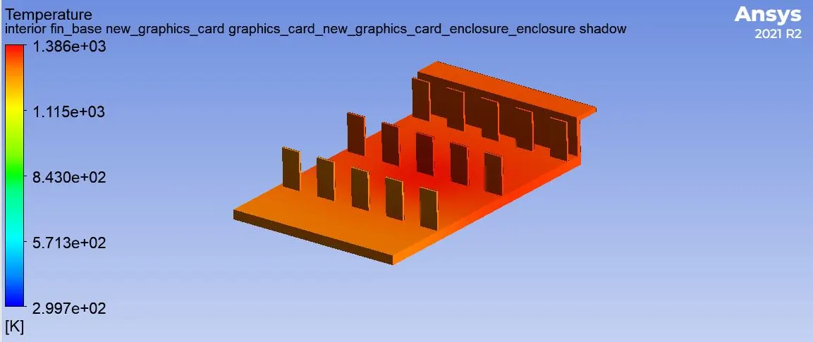
5 m/s Inlet Velocity-
Processor Temperature-
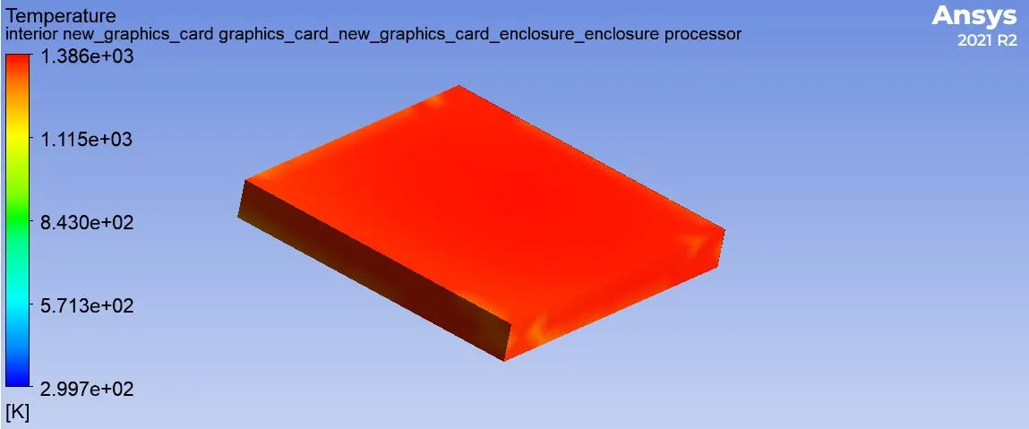
Base Surface Temperature-
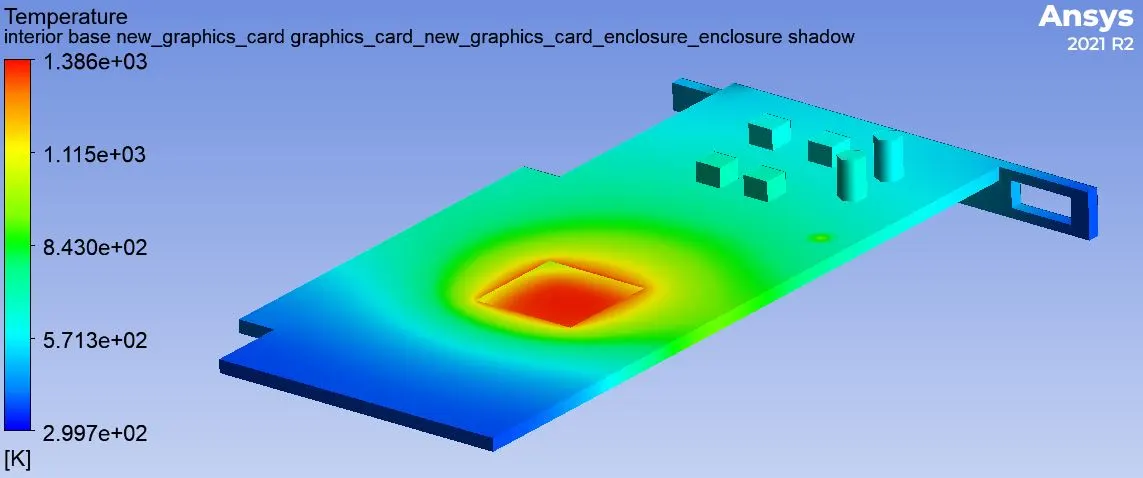
Fin Base Surface Temperature-
Processor Heat transfer Coefficient-
Graphic Card Heat Transfer Coefficient-
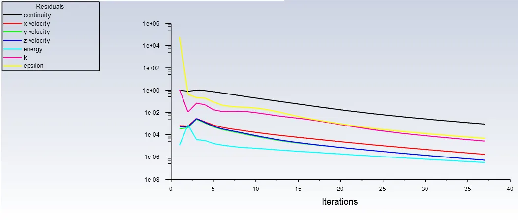
Sample Residual Plot-
Results-
| Velocity at Inlet Condition (m/s ) | Processor Temperature (K) | Processor Heat Transfer Coefficient (W/(m^2 K) |
| 1 (Rough Meshing) | 3008 | 577.9 |
| 1 (Refiine Meshing) | 2989 | 577.9 |
| 3 (Refined Meshing) | 1738 | 577.9 |
| 5 (Refined Meshing) | 1386 | 577.9 |
Conclusion-
- Heat Transfer coefficient is independent of meshing condition.
- Processor temperature depends on the condition mesh.
- Maximum processor temperature goes decreasing as inlet air velocity increases.
- Potential hot spot in the graphic card is obviously the processor.