Project 1 : CFD Meshing for Tesla Cyber Truck
Aim- To mesh Tesla Cybertruck
Procedure-
1. Download the model from challenges section of the website.
2. Opening the model in the ANSA.
3. Checked the model for single cons and possible tripple cons.
4. Some surfaces were missing in the model. Firstly, I created all the missing surfaces by using 'New' and 'Coons'
5. Checked surfaces for possible unnecessary surfaces but found none on them present.
6. There was some weird surface generation in the model I repaired them by creating new appropriate surfaces.
7. Once all the surfaces were present and no single and tripple cons were remaining I moved on to creating PIDs.
8. I created four PIDs in the first stage of the topological cleanup. Namely, Body, Wheels, Windows and Lights.
9.I isolated the parts which are to assigned to a respective PIDs using '!Not' option.
10. I applied respective parts to the appropriate PIDs by right clicking on the PID and selecting Apply and choosing those isolated parts one by one.
11. Once all the PIDs were created I moved on to deciding quality criteria for perticular PIDs.
12. Quality criteria-
Tria element for all the PIDs.
Body-
Target length- 3mm
Min Length- 2mm
Max Length- 4mm
Windows-
Target Length- 2mm
Min Length- 1mm
Max Length- 3mm
Lights-
Target Length- 4mm
Min Length- 3mm
Max Length- 5mm
Wheels-
Target Length- 2mm
Min Length- 1mm
Max Length- 3mm
13. I saved all the quality criterias by their respective names to make them avail easily at the time of need.
14. I edited Mesh Criteria visibility to the options of my choice.
15. I entered in hidden mode and classic mesh section of meshing option.
16. I isolated PIDs one by one and started with distinct PIDs that are not in direct contact with each other.
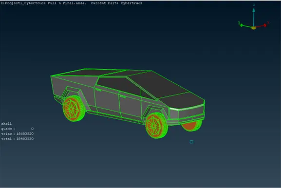
17. I selected respective quality criteria for respective PIDs and meshed them one by one.
18. After meshing every PID there were significant amount of off elements.
19. I first chose Restructure option from Shell Mesh and restructured the meshing. Still there were number of off elements.
20. Then I went with Reshape option from the Shell Mesh. This time after reshaping there were less number of off elemets making it possible to solve them individually by using move option from Grids.
21. Lastly I chose to mesh Body PID. As per quality criteria I selected Perimeter of the PID but carefully excluded the edges that were in direct contact with other PIDs. If I had selected those that would have caused complete mesh erasing of that other PID.
22. This way I meshed my last Body PID.
Wind Tunnel-
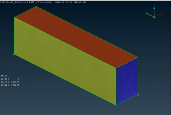
23. Now it was time for Wind Tunnel Creation.
24. I then measured approximate distance between two extreme possible points in the front viewand top view of the cybertruck and noted them down.
25. Base Face of the wind tunnel (WT) should be nearer to the wheen of the vehicle. Therefore I chose a distance of 700mm from the bottom point of the 'bonnet' of the cybertruck and created a point there (Pt1)
26. For front face of WT 5*x, i.e. x= total length of the car, is the appropriate distance so I created Pt2 there.
27. For left and right hand side of WT, (1/2)*width + x, i.e. x= total length of the car, is the appropriate distance, so created two points Pt3 and Pt4 at left and right hadn side of Pt2 respectively.
28. For rear face of WT 6*x, i.e. x= total length of the car, is the appropriate distance but from Pt1 it is (6*x)+x= 7*x.
Therefore I created Pt5 there.
29. For left and right hand side of WT form Pt5 on the left and right hand side I created Pt6 and Pt7 respectively at (1/2)*width + x, where x= total length of the car, distance.
30. I chose to create curves there. So I created curves between Pt3 & Pt4, Pt6 & Pt7.
31. Now I created Base face of the WT using New option in Faces.
32. To create top face of WT I chose offset option of Faces section in Topo and created it at the distance of (Height of the car + 3*x), where x= total length of the car.
33. Now with those two edges I created front and rear face of the WT.
34. I created PIDs for all the faces of the WT individually and applied them to each one of them.
35. Firstly I meshed top and bottom (base) faces of the WT. For top face 400mm is the target length and for bottom face 80mm is the target length. I meshed them using conventional method of meshing.
36. Before meshing front and rear face of the WT, I chose spacing option in 'Classic Mesh' 'Perimeters' section. I chose Geometric Biasing, factor 1.2, Dstart- 80mm, Dlimit- 400mm. I chose the edges of the front and rear face of the WT and pressed OK.
37. Before meshing fornt and rear face of the WT I deavticated Min length and Max length quality criterias. and then chose 'Spot Mesh' select and selected the front face and middle clicked. It was now meshed with the variable mesh length.
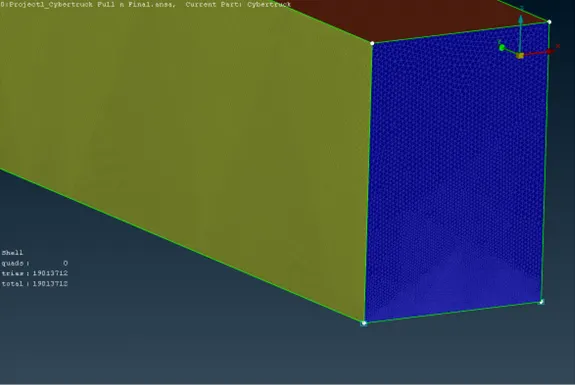
38. In a similar way I meshed Rear face, left hand and right hand side of the wind tunnel one by one.
Learning Outcomes-
I was able to-
-create missing surfaces
-solve single and tripple cons
-create PIDs
-mesh all the PIDs
-create wind tunnel
-mesh it with variable mesh length
Result-
As a result of complete and successful meshing the ANSA has created 19013712 tria elements with zero off elements for respective quality criteria of the PIDs.
Conclusion-
It is important to have finer mesh size near and at the area of interest. I successfully completed the challenge.
Google drive link of the model-
https://drive.google.com/file/d/1ksZL8nxbt5C0tE3BX3el5gbNs9ExNUrs/view?usp=sharing
!!THANK YOU!!
https://drive.google.com/file/d/1ksZL8nxbt5C0tE3BX3el5gbNs9ExNUrs/view?usp=sharing