Week 7 - CHT Analysis on a Graphics card
AIM
To perform the steady-state conjugate heat transfer analysis on the given model of a graphics card.
OBJECTIVES:
- Conduct the simulation, adjusting the velocity within the range of 1 m/s to 5 m/s for a minimum of three different velocities, and analyze the outcomes.
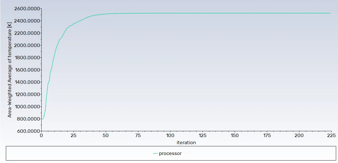
- Determine the peak temperature and heat transfer coefficient achieved by the processor during the simulation.
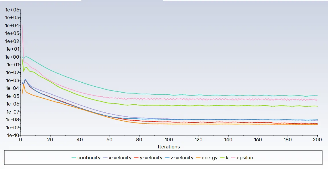
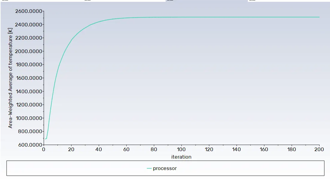
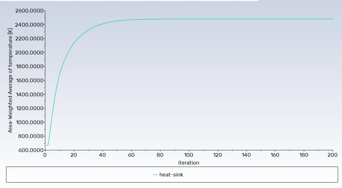
- Validate the convergence of the simulation through the presentation of relevant images and plots.
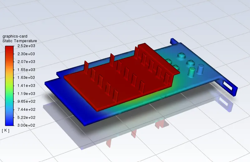
- Identify potential hotspots on the model where temperature concentrations are particularly high.
INTRODUCTION:
A Graphics Processing Unit (GPU) is a vital component in contemporary computer devices, responsible for executing graphical computations to produce the user interface output. Given that high-performance GPUs generate substantial heat, maintaining effective cooling is crucial. Elevated temperatures not only pose a risk of damaging or shortening the lifespan of the GPU but can also adversely impact its computational efficiency. Improved cooling solutions and lower temperatures allow GPUs to operate at higher frequencies, resulting in enhanced performance.
Consequently, Computational Heat Transfer (CHT) analysis has emerged as a critical aspect of the GPU industry. This analysis is essential for designing an optimal thermal management system for graphic cards, ensuring that heat dissipation is efficiently handled. By conducting CHT analysis, manufacturers can fine-tune cooling systems to keep GPUs within an optimal temperature range, maximizing their longevity and overall performance capabilities.
Commonly used materials in graphic cards components:
1. Base or Printed Circuit Board (PCB):
- Fiberglass: Provides structural support.
- Copper Foil: Used for electrical conductivity in the circuit traces.
- Tin Lead Antimony (SnPb₂): Commonly used in soldering for connecting electronic components.
- Epoxy Resin: Used as a substrate material for the PCB.
The base material is not explicitly mentioned, but it is likely a combination of materials such as fiberglass and epoxy resin for structural support and insulation.
2. Cooling Fins:
Copper: Used for its high thermal conductivity to transfer heat away from the GPU.
3. Heat Pipes:Material composition is not explicitly mentioned, but common materials include copper or aluminum for efficient heat transfer.
4. Shroud:
Injection Molded Plastic: The shroud is likely made of plastic, possibly ABS or another thermoplastic material.
5. Fans:The fan blades are typically made of plastic (commonly ABS or similar materials).
CONJUGATE HEAT TRANSFER (CHT):
Conjugate Heat Transfer (CHT) analysis enables the simulation of heat exchange between solid and fluid domains, facilitating the study of various applications such as heat exchangers, electronic equipment cooling, and general-purpose heating and cooling systems.
Convective Contribution:Dominance of conduction and convection varies based on fluid properties and flow region.
Viscous Effects:Negligible in many cases but considered for high-velocity scenarios.
Density Effects:Variation in density due to temperature, causing compression and generating heat.
Contemporary conjugate convective heat transfer models have evolved with the widespread use of computers, replacing empirical relations with mathematically stated problems. This model describes heat transfer between a body and fluid, considering physical processes and solutions separately for each object.
Applications of Conjugate Heat Transfer:
Examples of Applications:
- HVAC, Heat Exchanger, Tank, Internal Combustion Engine, Heat Sink, Boiler, Reactor, Heat Pipe, Turbocharger.
- Heat Transfer in a Solid - Conduction:The diffusion of heat in solids due to temperature gradients. Conduction is described by Fourier’s law, where heat flux (q) is proportional to the temperature gradient.
- Heat Transfer in a Fluid - Convection: Heat carried away by moving fluid, either through external influences (forced convection) or buoyancy forces (natural convection). Fluid motion contributes to convective heat transfer, viscous effects, and density effects.
Used extensively in various areas from aerospace and nuclear reactors to medical procedures and meteorology. Applications include analyzing temperature distributions, thermal stress, time-dependent heating/cooling problems, and overall heat transmission coefficients.
The accurate description of material properties, flow regimes, geometric configurations, and appropriate models is crucial for analyzing temperature fields and heat transfer. Practical CHT issues are addressed, including determining temperature extremes, assessing temperature-related stress, studying time-dependent temperature responses, and calculating overall heat transmission coefficients. Conjugate Heat Transfer analysis proves indispensable for optimizing thermal management in systems involving both solid and fluid components.
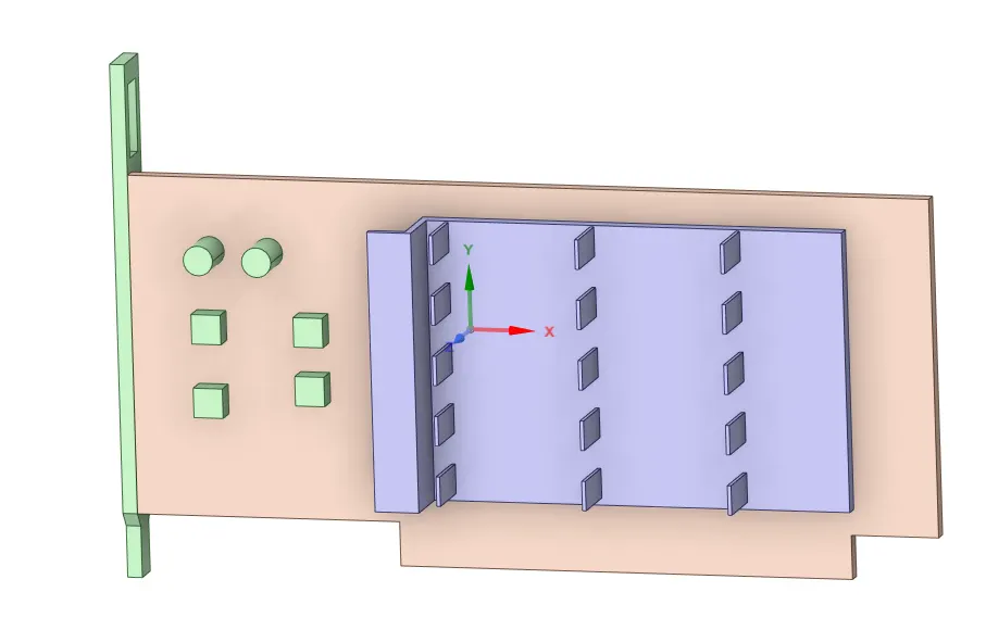
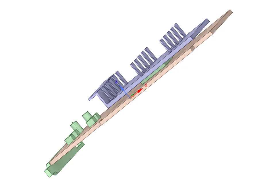
Graphics card Model:
Top view:
Side view:
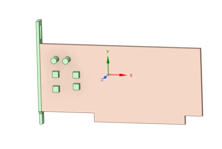
Parts of Graphics card:
(a) Base:
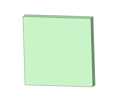
(b)Processor:
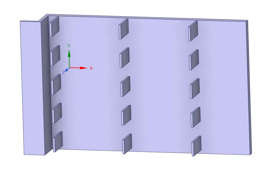
(c)Heat Sink:
Encloser:
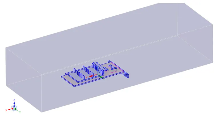
Share topology enabled.
MATERIAL:
| Part | Material | Density (kg/m^3) | Specific Heat J/(Kg.K) |
Thermal Conductivity W/(m.K) |
| Base | FR4 | 1850 | 950 | 0.29 |
| Fin Base | Copper | 8978 | 381 | 398 |
| Processor | Silicon | 2330 | 705 | 149 |
| Enclosure | Air | 1.225 | 1006.46 | 0.0257 |
MESHING:
Mesh-1:
Meshing Information-
Entire body was meshed using three body sizing options.
Mesh size - 3 mm.
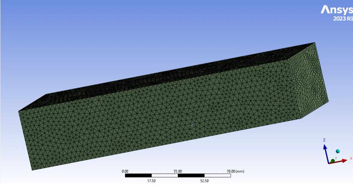
Body Sizing-
Base- 2 mm.
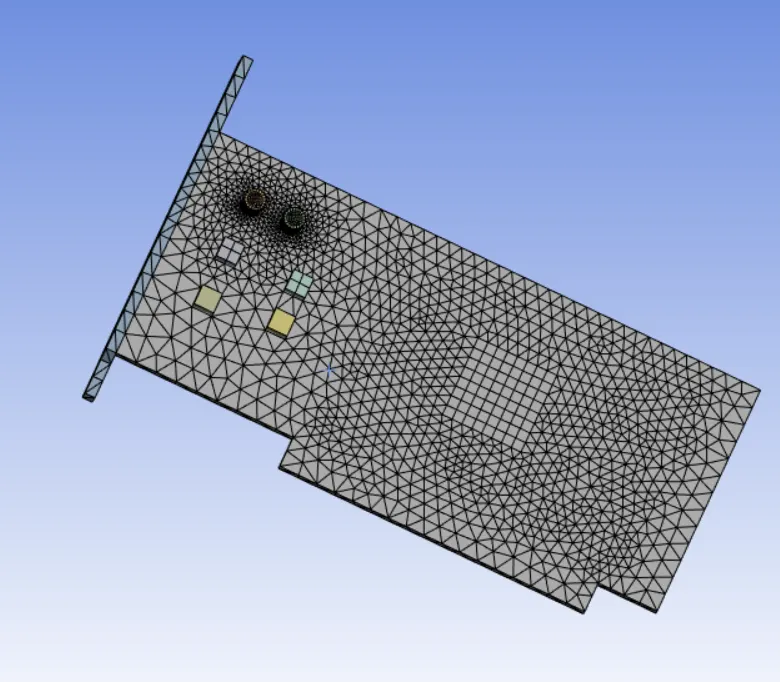
Heat sink- 1 mm.
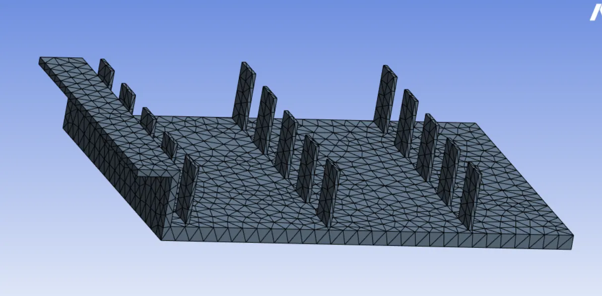
Processor- 1 mm.
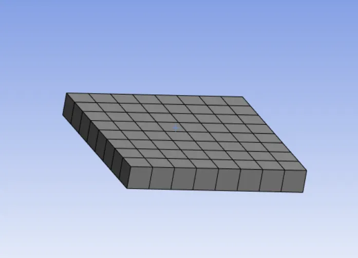

FLUENT SETUP:
- Setting up the physics :Setting up the physics for CHT analysis on a graphics card in ANSYS fluent.
- For this case we are using pressure-based steady state solver
- Velocity formulation - Absolute
- Model setup
Energy
Viscous - k-omega - Workstation-class GPUs designed for professional applications (e.g., content creation, 3D modeling, CAD) may have power consumption ranging from 75 watts to over 300 watts.
- Low-Power or Integrated Graphics:Integrated graphics solutions or low-power dedicated GPUs found in some laptops or budget systems may have lower power consumption, often below 75 watts.
Setting Source properties for the Heat Dissipation -
Since the processor acts as the heat source, specify the calculated heat generated.
For this simulation, let’s assume that the processor consumes 75W of energy and converts all of it into heat. The dimensions of the processor are 8mm x 8mm x 1mm.
Then the heat generated per volume will be :
Heat Generation rate `= (Power)/(Volume) = 75/(8**8**1**10^3)` = `1.19*10^9``W/m^3`
CASE 1:
Mesh-1 setting with 1m/s
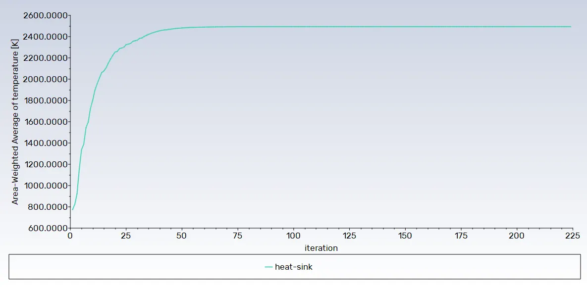
Residual Plot:
Temperature plot for processor:
Temperature plot for sink:
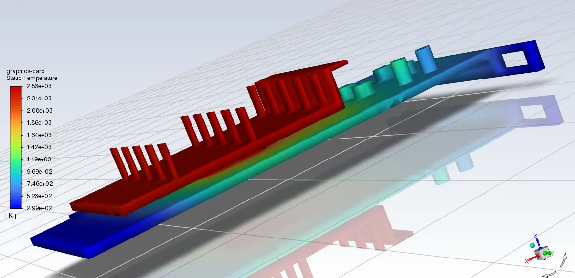
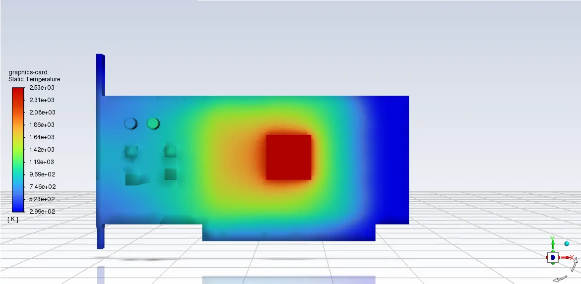
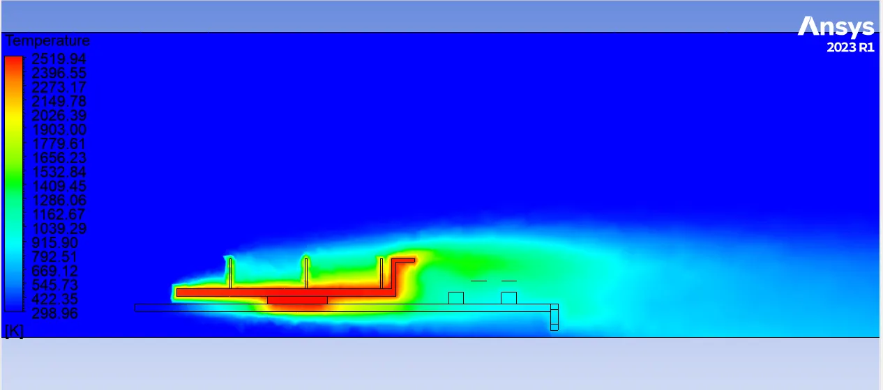
Graphics card temperature distribution:
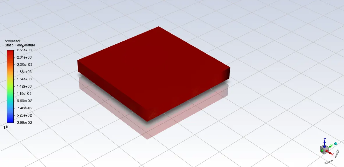
Processor temperature distribution:
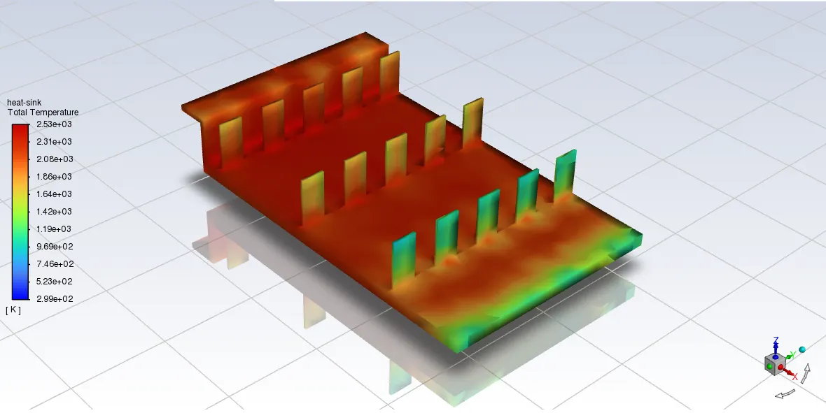
Heat sink Total temperature distribution:
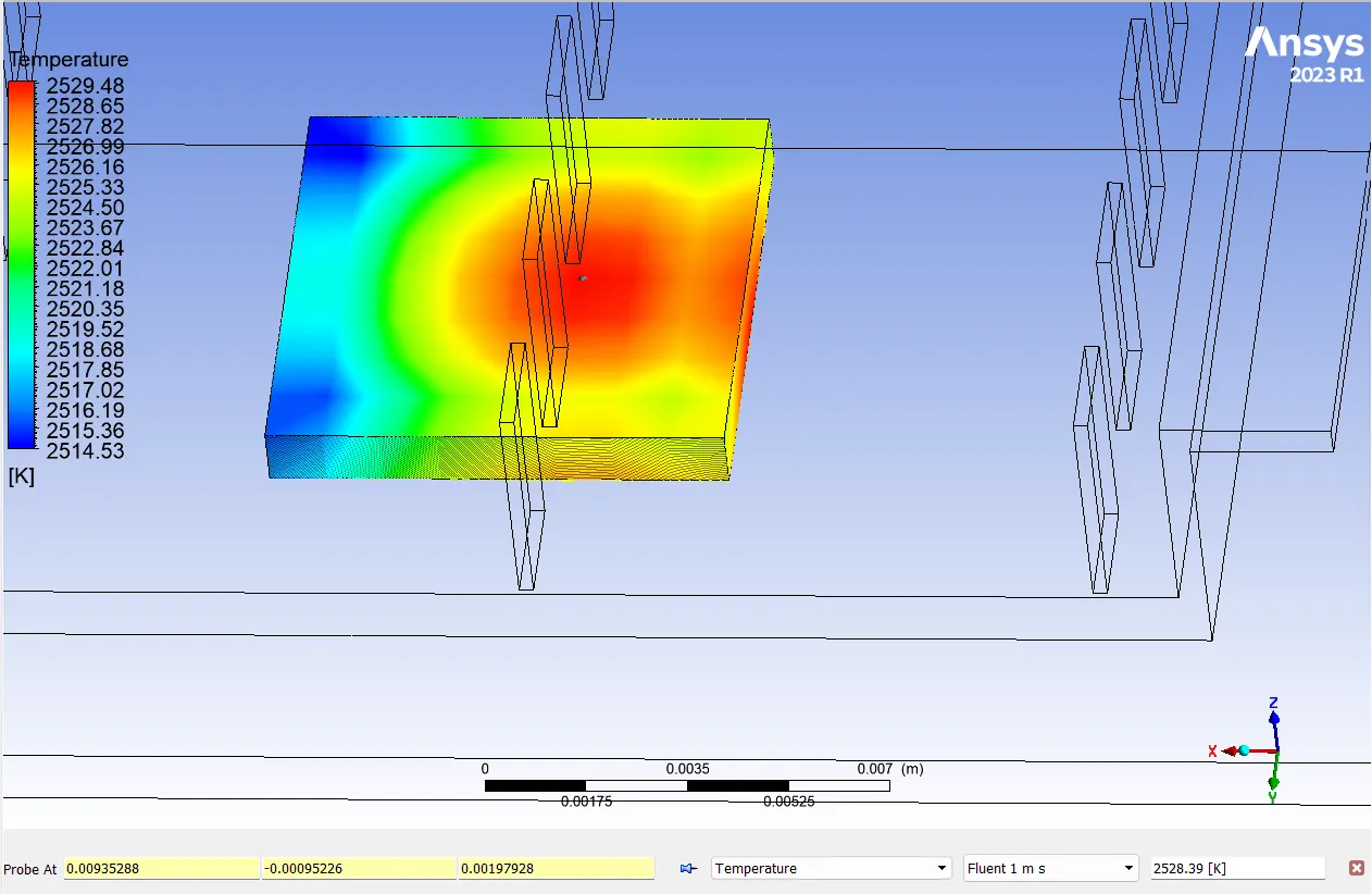
Hotspot region on GPU:
(a)Top view:
(b) Bottom view:
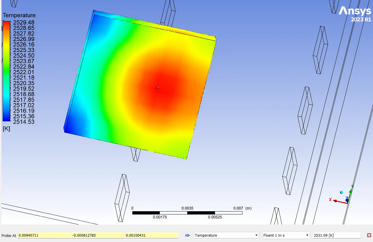
The processor top side hot spot temperature is 2528.39 C and bottom temperature is 2531.09 C.
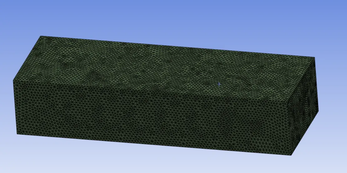
Mesh-2:
Meshing Information-
Entire body was meshed using three body sizing options.
Mesh size - 2 mm.
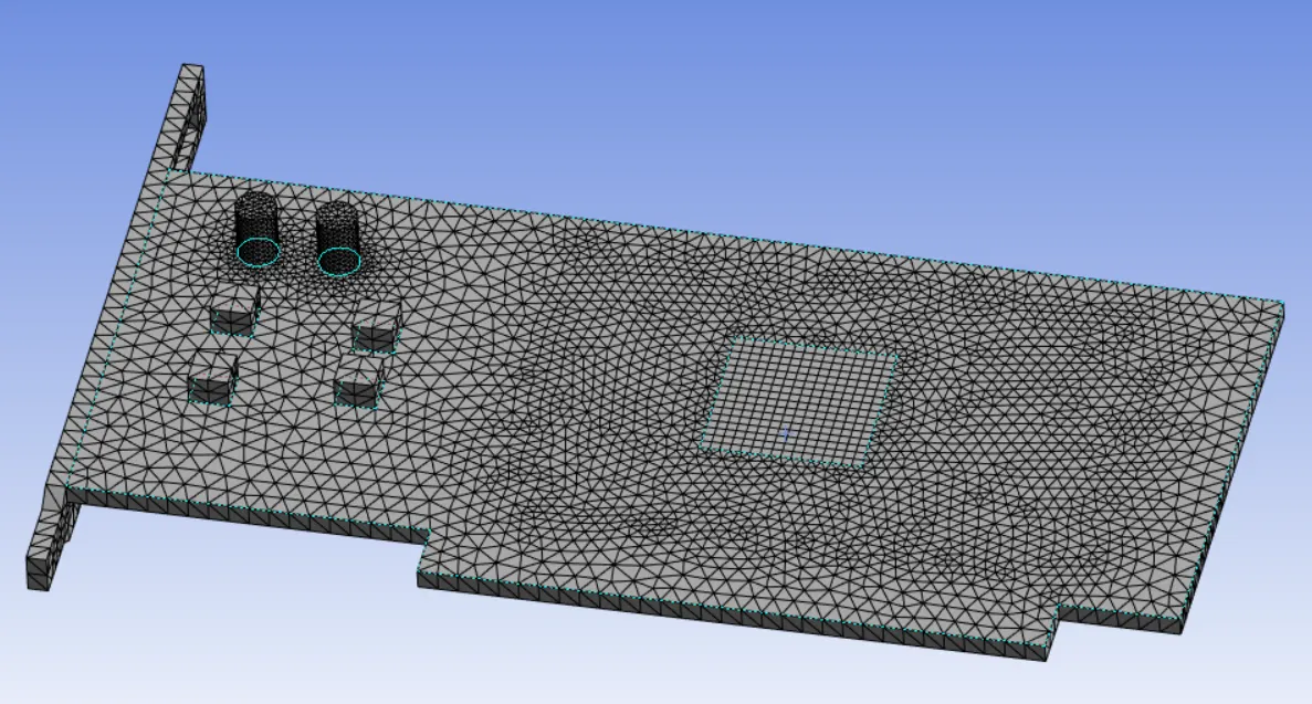
Body Sizing-
Base- 1 mm.
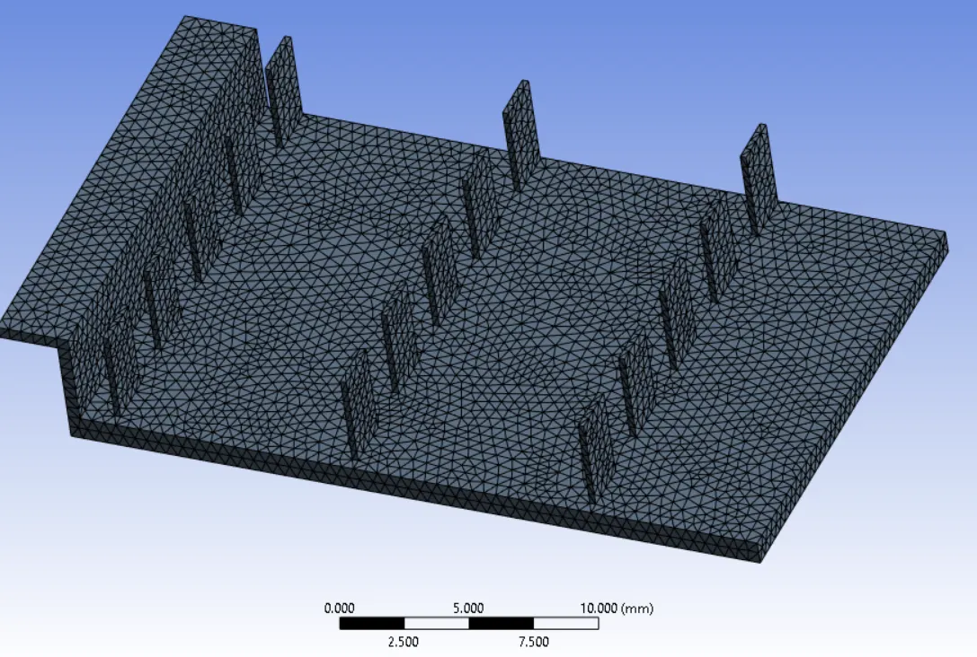
Heat sink- 0.5 mm.
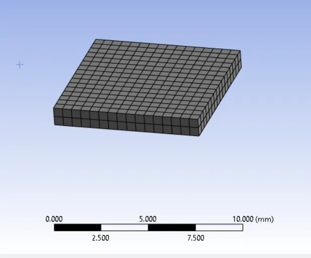
Processor- 0.5 mm.

CASE 2:
Mesh-2 setting with 1m/s
Residual Plot:
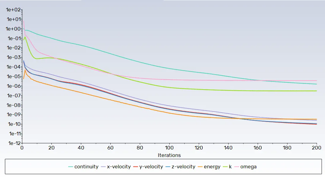
Temperature plot for processor:
Temperature plot for sink:
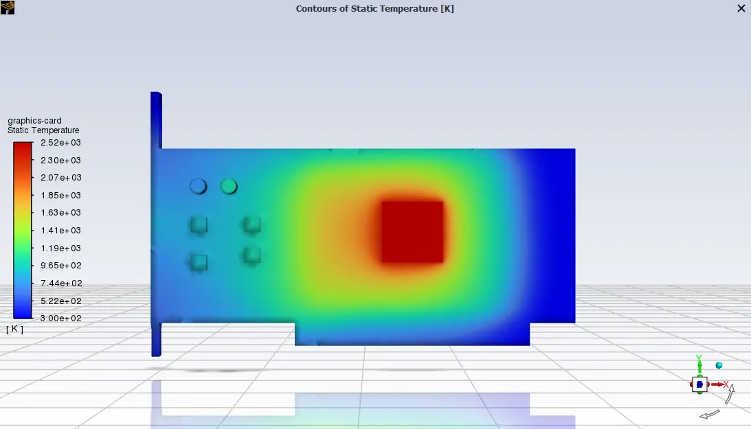
Graphics card temperature distribution:
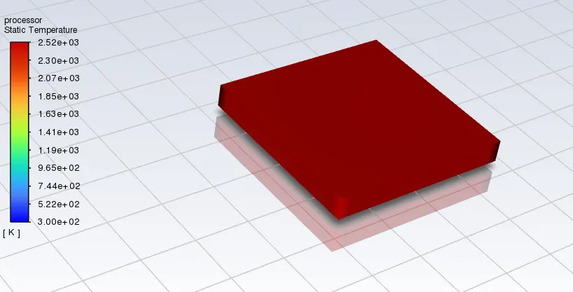
Processor temperature distribution:
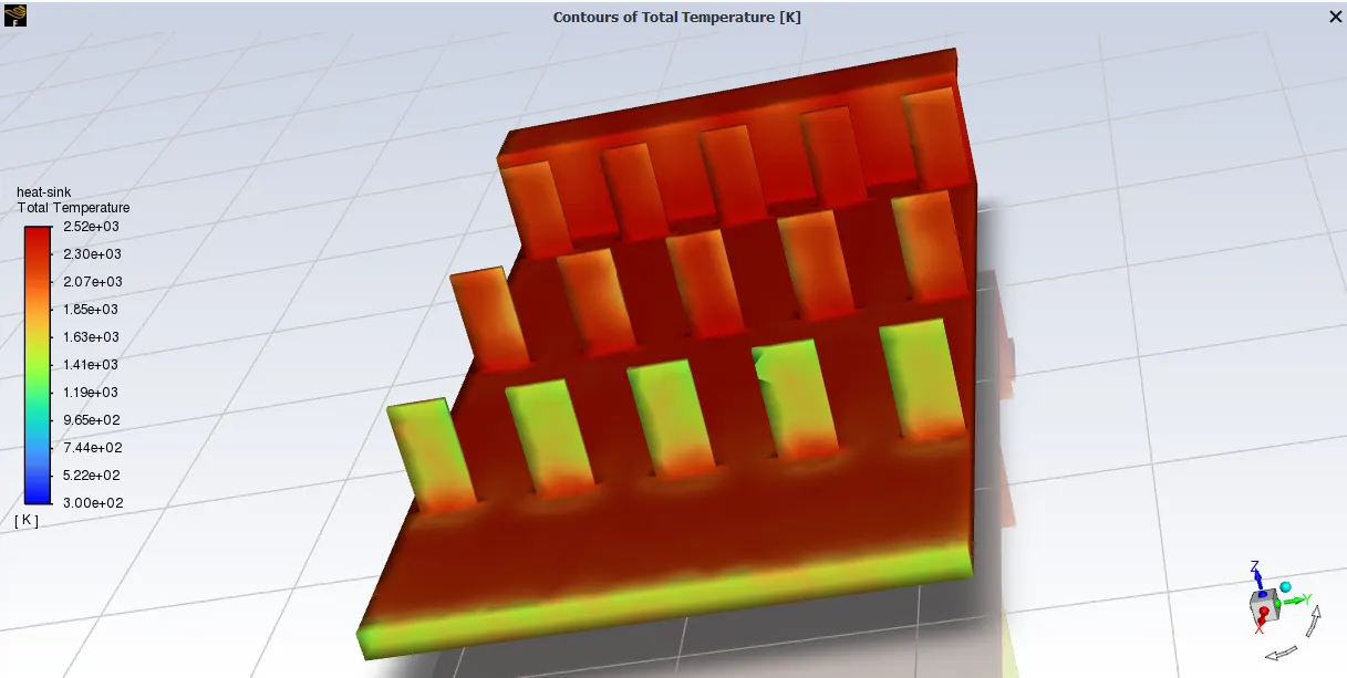
Heat sink Total temperature distribution:

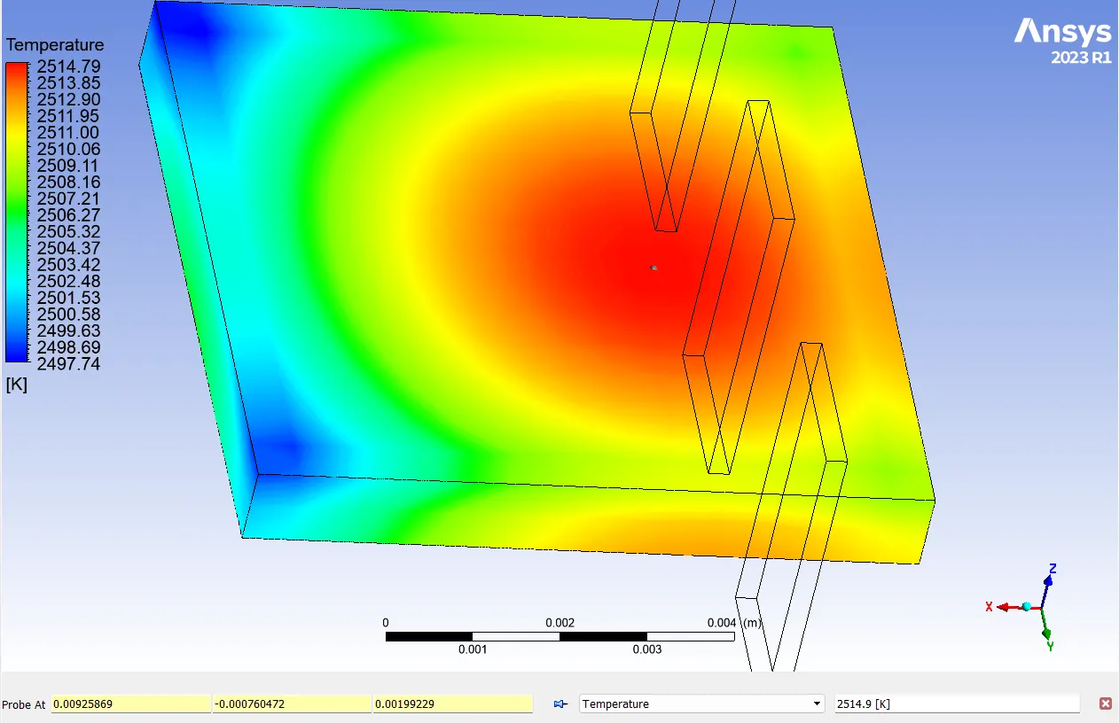
Hotspot region on GPU:
(a)Top view:
(b) Bottom view:
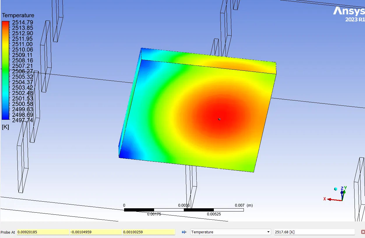
The processor top side hot spot temperature is 2514.9 C and bottom temperature is 2517.68 C.
CASE 3:
Mesh-2 setting with 3m/s
Residual Plot:
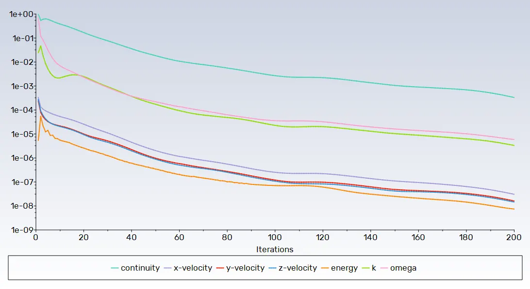
Temperature plot for processor:
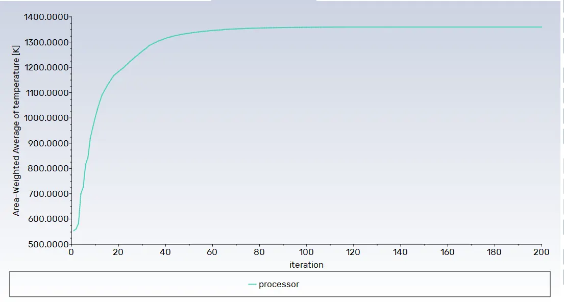
Temperature plot for heat sink:

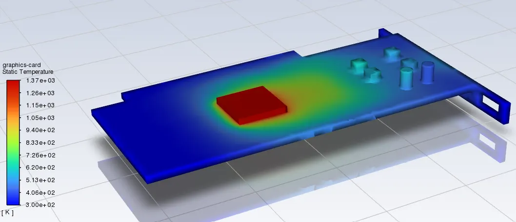
Graphics card temperature distribution:
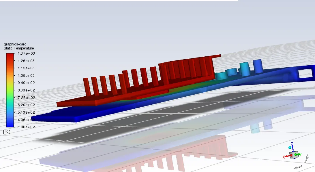
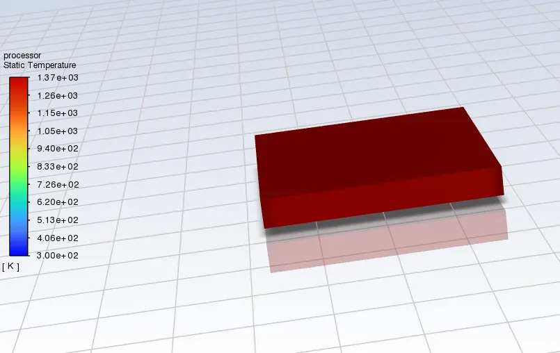
Processor temperature distribution:
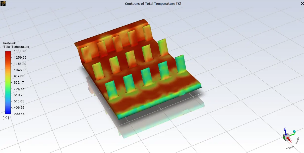
Heat sink Temperature distribution:
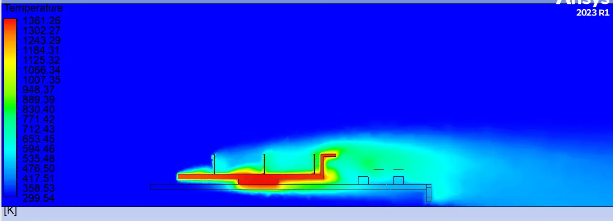
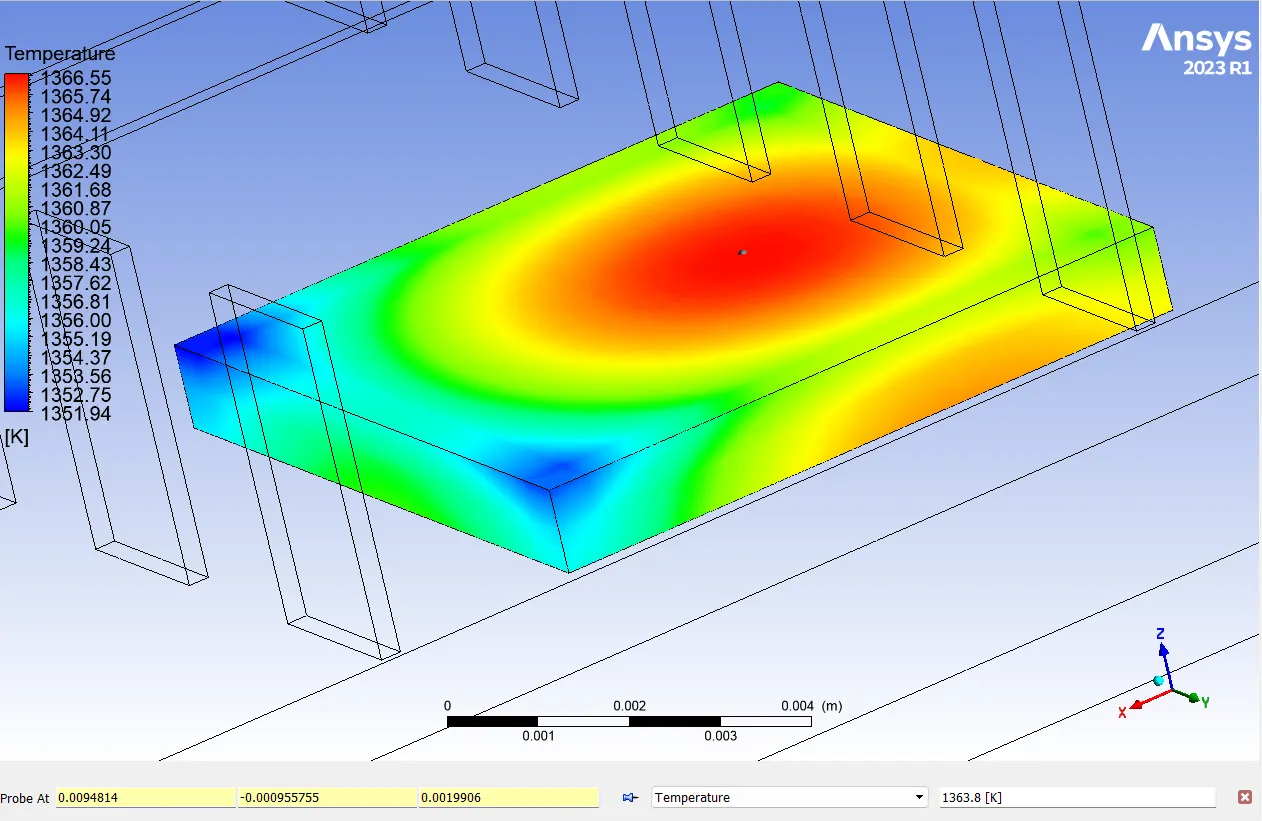
Hotspot region on GPU:
(a)Top view:
(b) Bottom view:
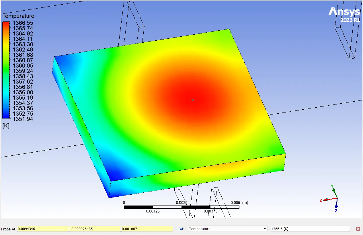
The processor top side hot spot temperature is 1363.8 C and bottom temperature is 1366.6 C.
CASE 4:
Mesh-2 setting with 5m/s
Residual Plot:
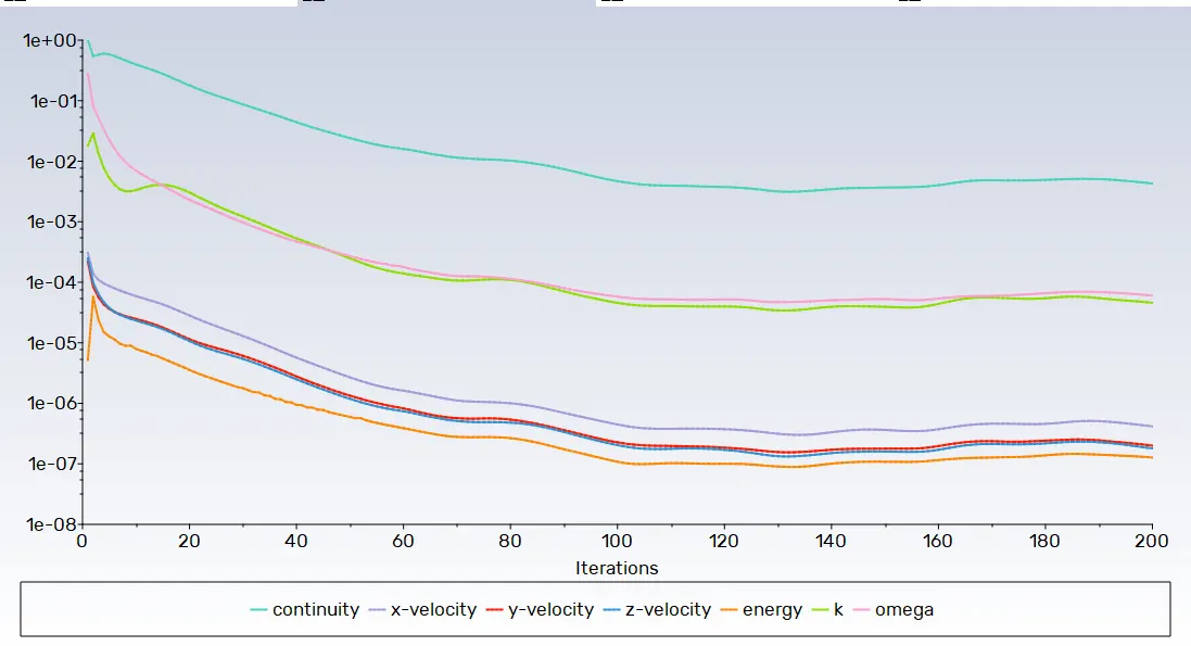
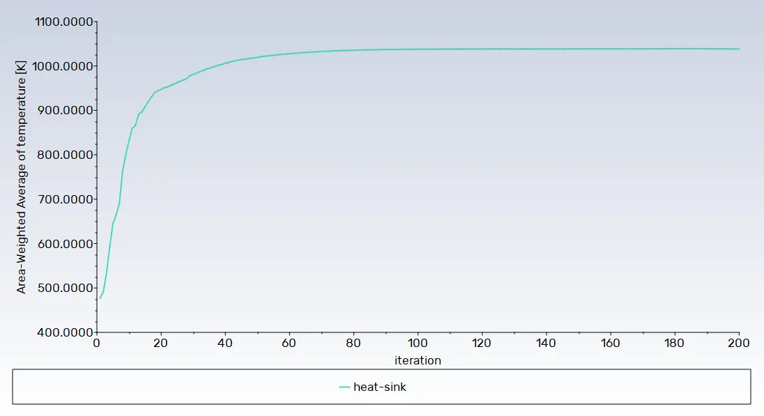
Temperature plot for processor:
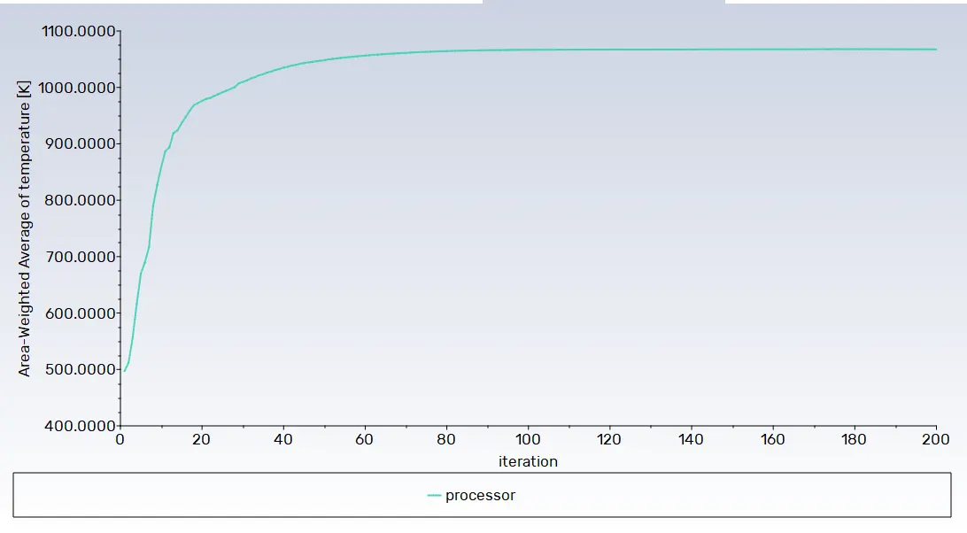
Temperature plot for sink:
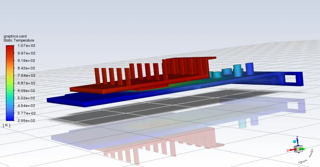
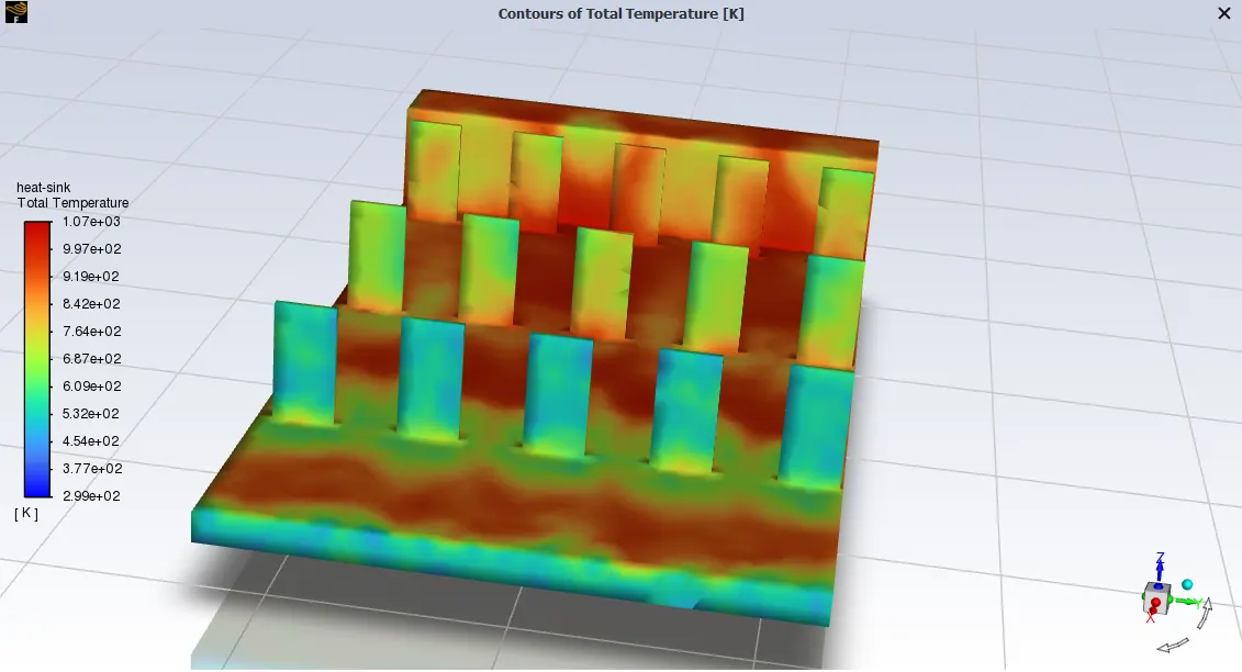
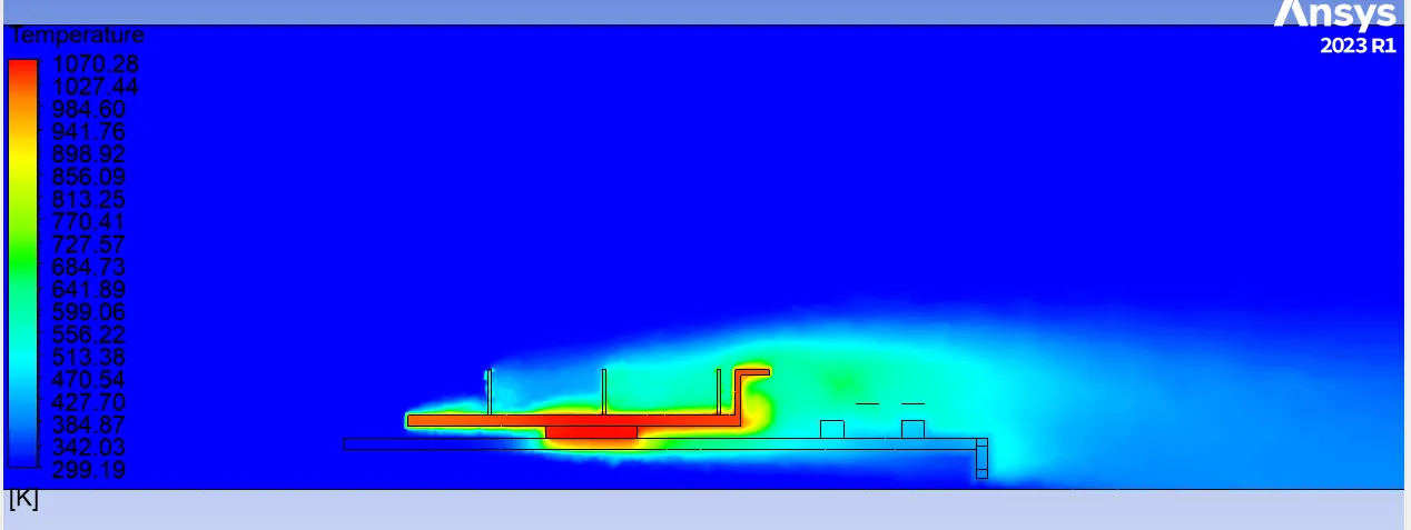
Graphics card temperature distribution:
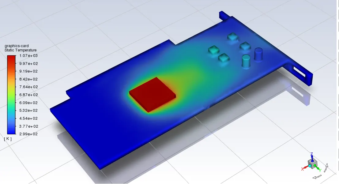
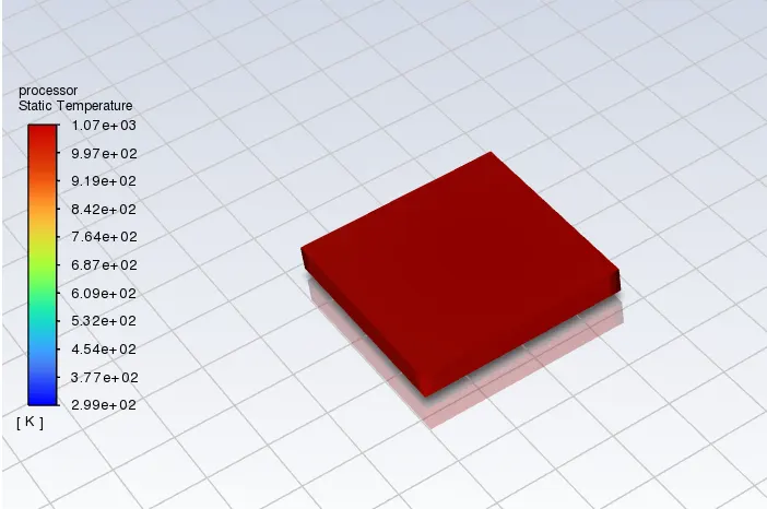
Processor temperature distribution:
Heat sink Temperature distribution:
Hotspot region on GPU:
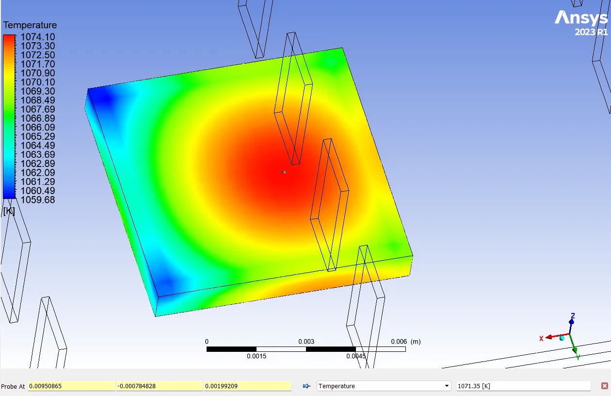
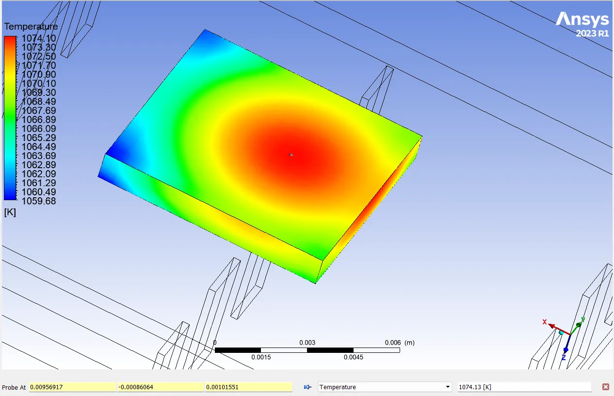
The processor top side hot spot temperature is 1071.35 C and bottom temperature is 1074.13 C.
The temperature fluctuation on the processor is attributed to the interaction of various materials with distinct thermal properties.
---------------------------------------------------------------------------------------------------------------------------------------
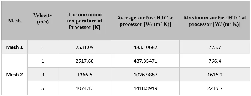
Result parameters for different velocity cases:
Conclusion:
- The choice of copper for the fins significantly contributes to efficient heat dissipation due to its excellent thermal conductivity.
- Higher velocities result in decreased hotspot temperatures, indicating improved overall cooling efficiency.
- Finer mesh resolutions yield more accurate results and provide more detailed temperature contours for analysis.
- As the velocity increases from 1 m/s to 5 m/s, the average temperature at the processor decreases, accompanied by an increase in both average and maximum surface heat transfer coefficients.
- Mesh-2 with a finer mesh size provides more accurate results compared to Mesh-1, demonstrating the importance of mesh refinement in capturing detailed thermal behavior.
- The observed trends suggest that optimizing velocity and mesh resolution can lead to better thermal management strategies for graphics cards, ensuring optimal performance and longevity.
Refrences :
- Conjugate Heat Transfer - https://www.comsol.com/blogs/conjugate-heat-transfer/
- Advanced Cooling for Power Electronics - https://www.electronics-cooling.com/2017/07/advanced-cooling-power-electronics/