Week 7 - CHT Analysis on a Graphics card
OBJECTIVE
To Perform Conjugate heat transfer Analysis on a Computer graphics card using Ansys fluent and to run the simulation with two different mesh sizes.
THEORY
Conjugate Heat transfer Analysis
It is a Heat transfer analysis involving two different mediums i.e solids and fluids . Heat transfer takes place in a conductive form with solids and convective form with fluids.
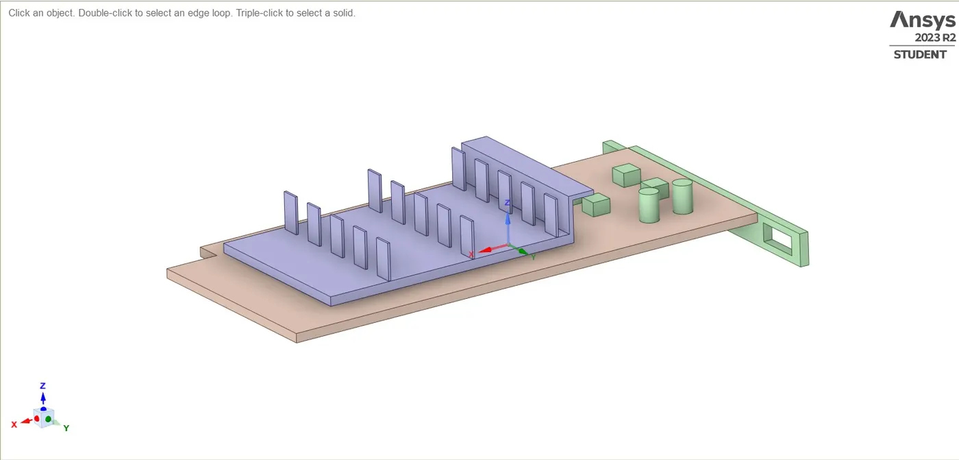
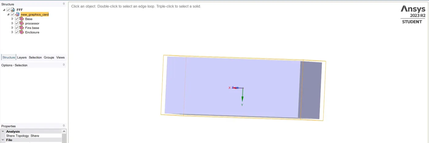
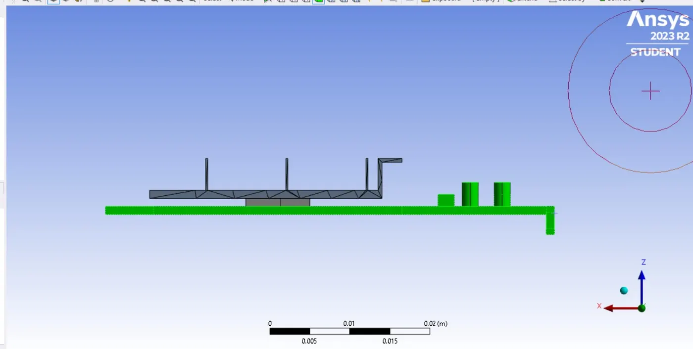
A typical graphics card geomtery is used for the simulation consisting a base, proccesor, and air fins
GEOMETRY
MESH
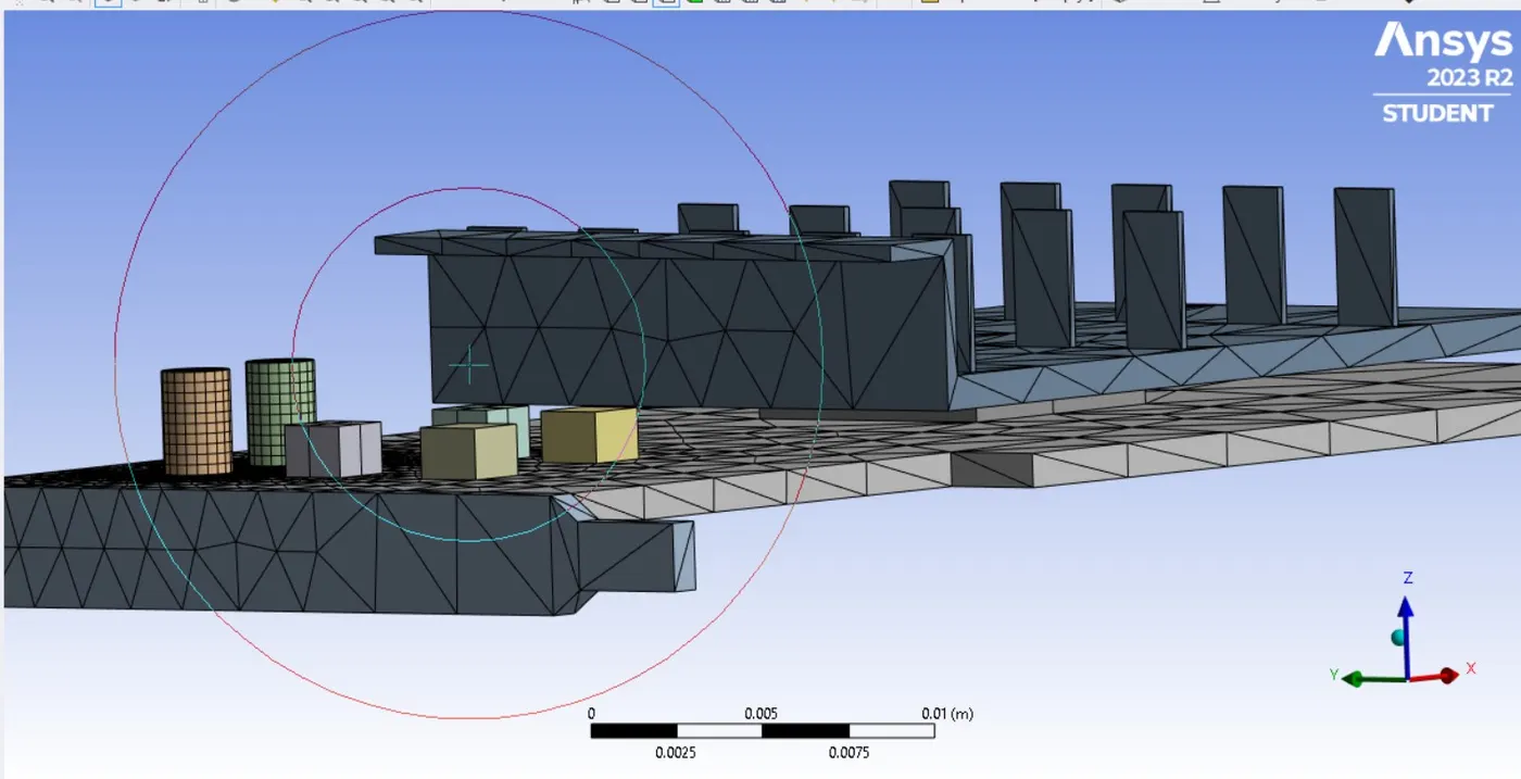
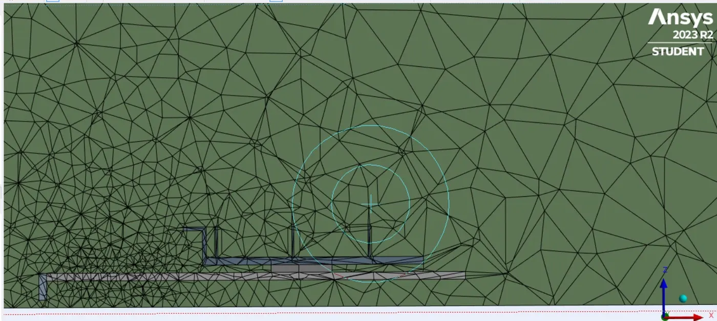
Base level mesh
Total mesh elements - 15729
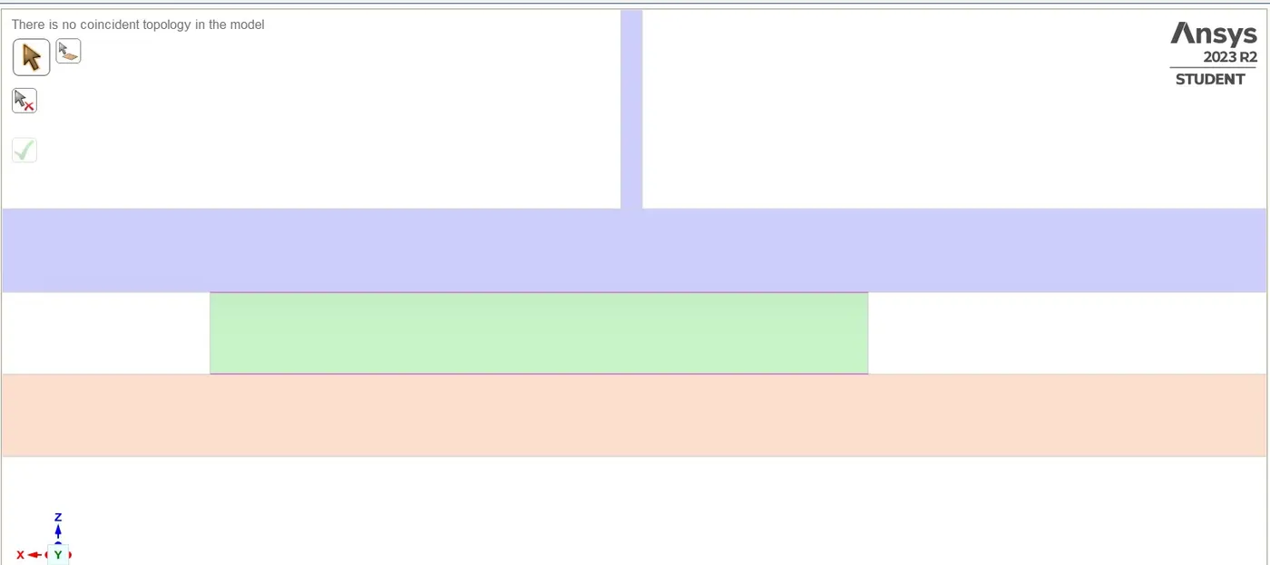
SETUP
The simulation is ran for steady state convergence option with energy function enabled as in this simulation the heat sourced from the proccesor is transferred to Air fins and to the base.
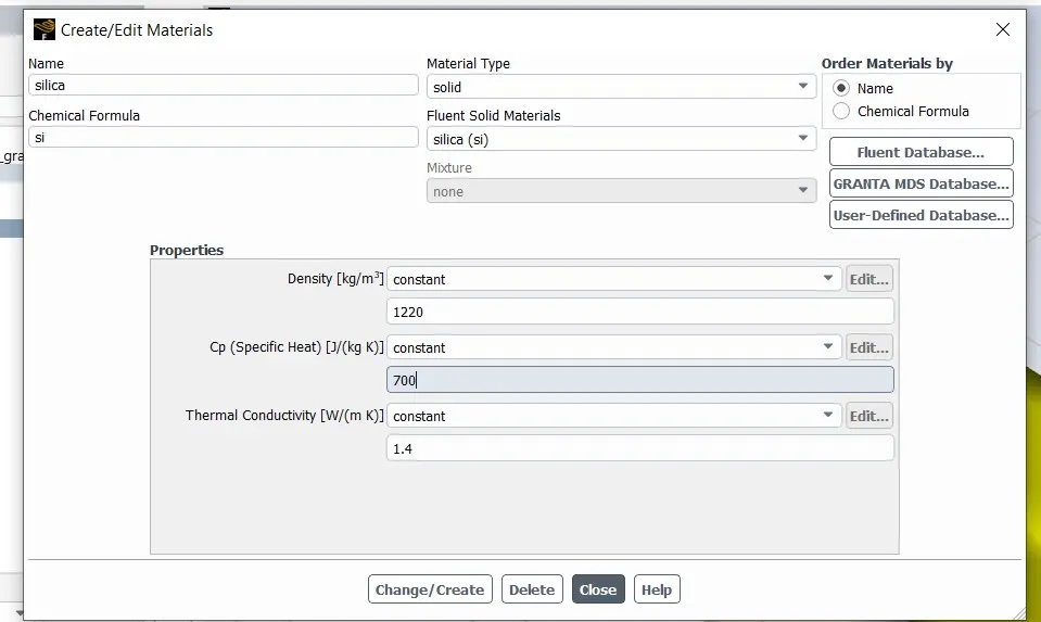
Differentiating the graphics card as proccesor, base, and fins and naming them with respective functional materials to perform the simulation. Here silica is used for the proccesor material and the physical entities such as specific heat and thermal conductivity is valued in reference .
Silica
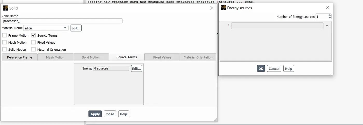
Cell Zones and boundaries are named as cell zone identifies the individual volume and is used fro physical boundary definition or source defintion. Boundaries are differentiated from cell zones as it implies with surface of the named selection.
Heat generated in watts - 100W
Volume of the proccesor - LxBxH= 0.008 x 0.008 x 0.001 = 6.4e-08m
Heat source generated in (W/m^3) = 15625000000
Velocity Inlet - 2m/s
RESULTS
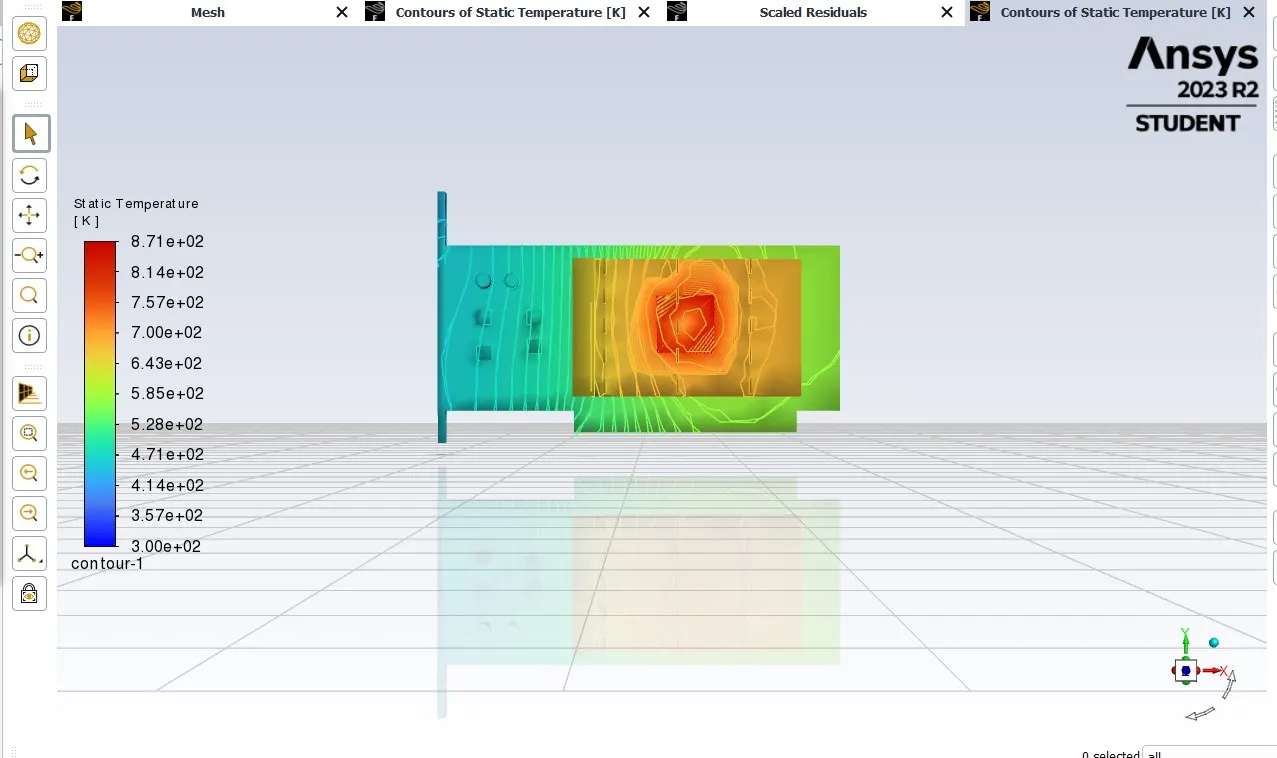
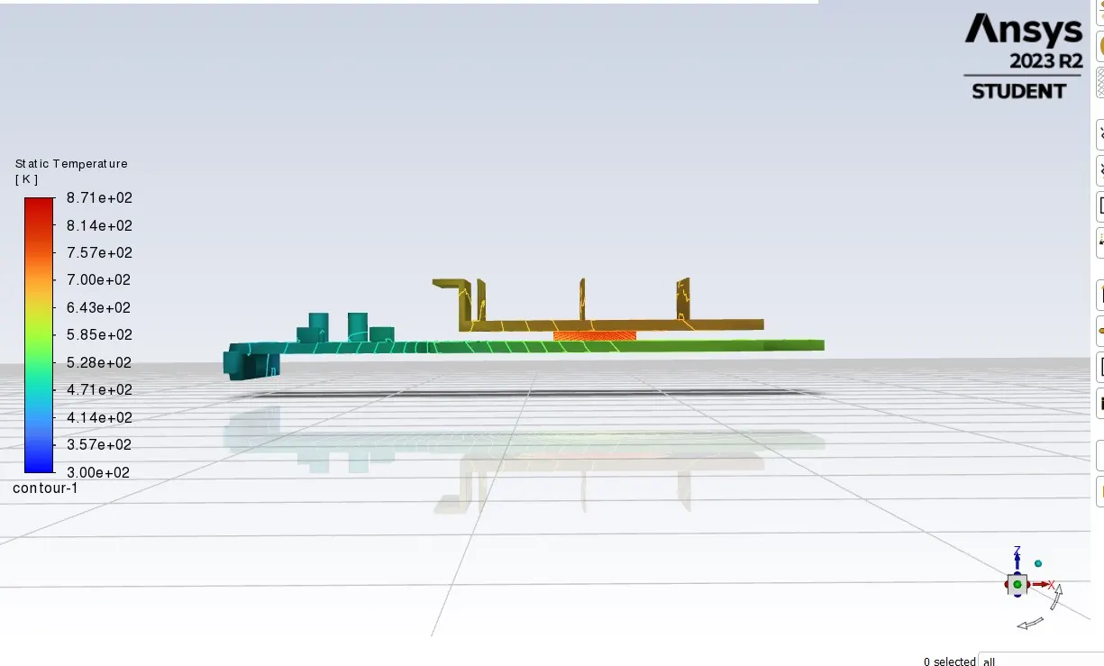
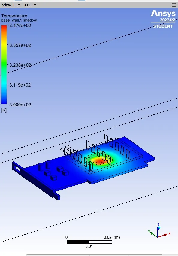
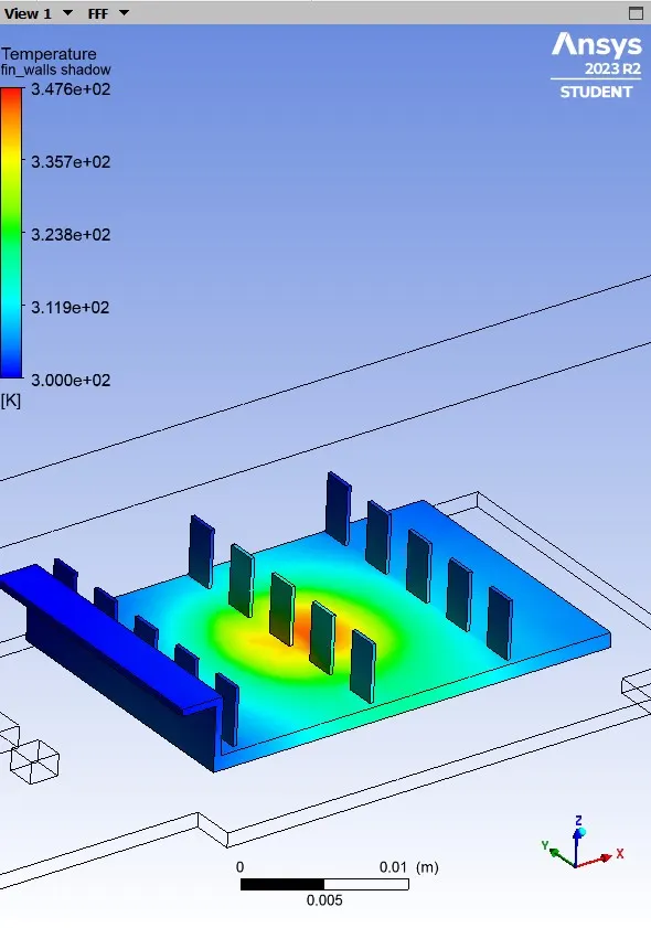
Proccesor is the hotspot area as it generates the heat and distriputes it.
POST PROCESSING
Surface heat transfer on the air fins
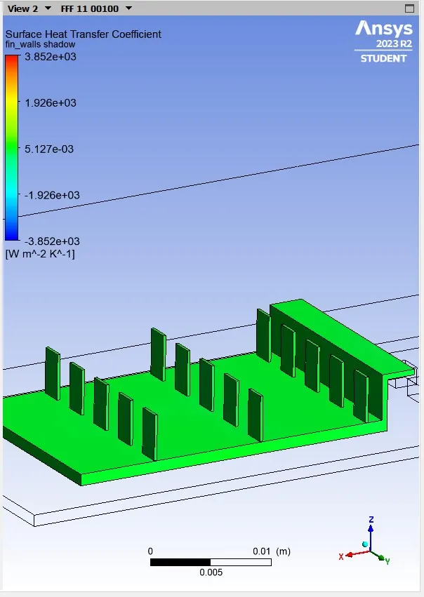
Wall heat transfer on bottom
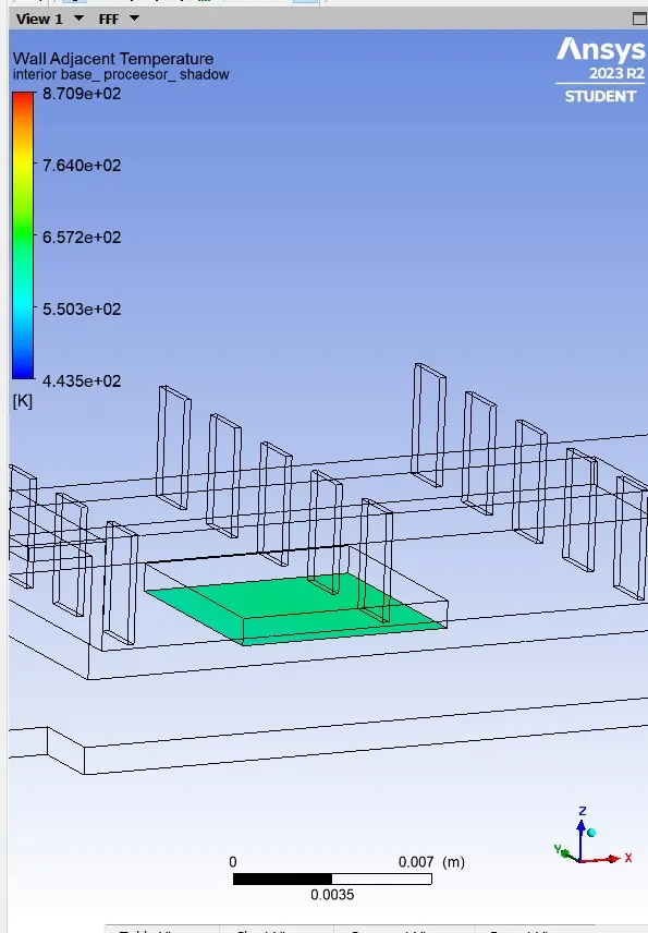
Wall heat transfer on top side
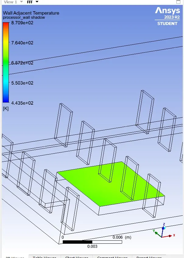
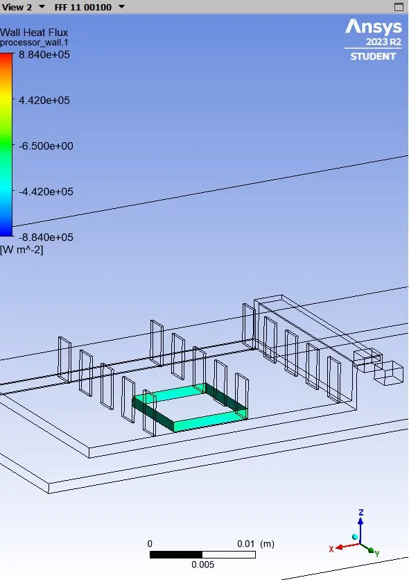
Heat flux on the side wall of processor
CASE 2
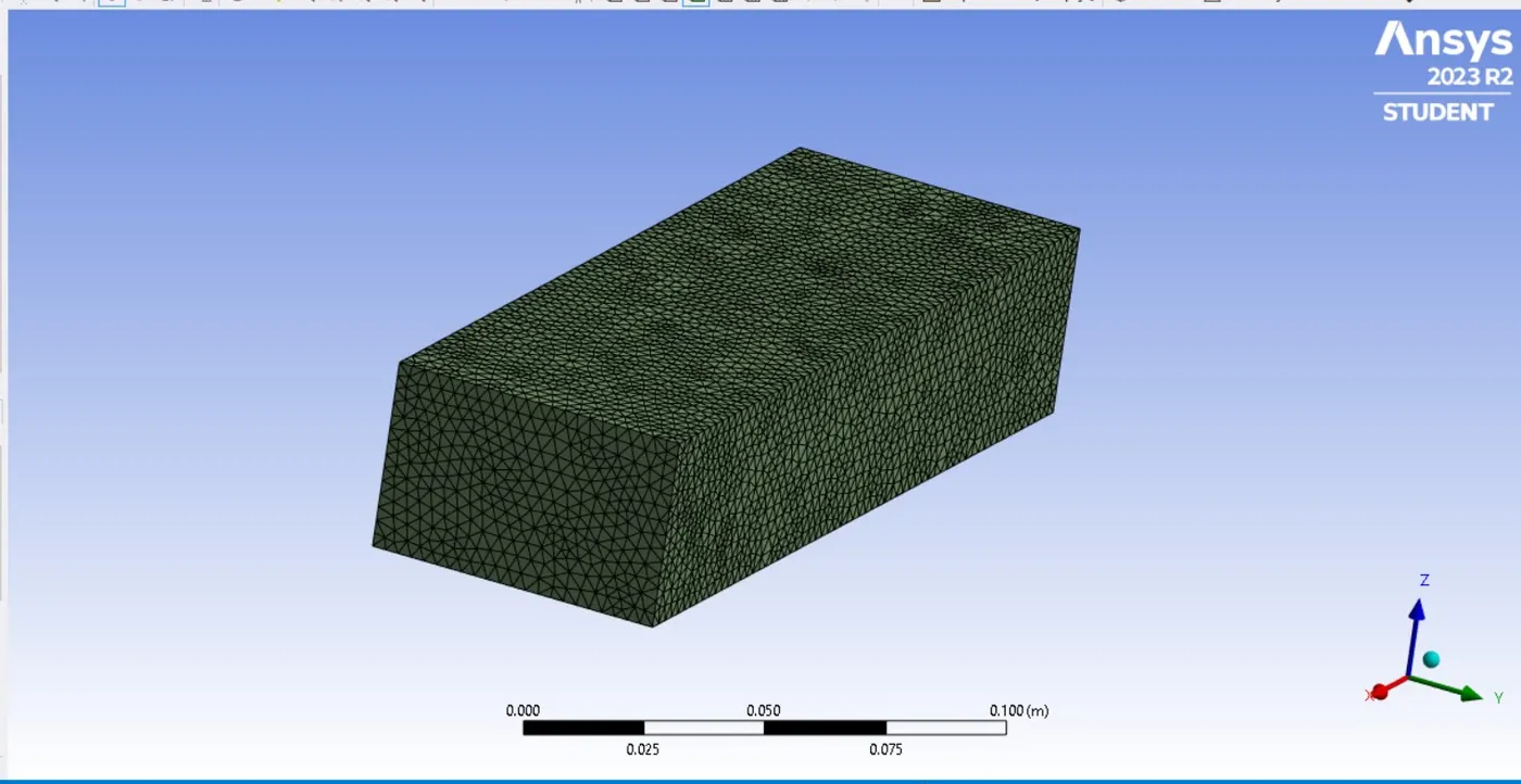
Mesh size - 3e-3m
Total mesh elements - 166503
Mesh geometry
SETUP
As the mesh is refined the temperature distribution while simulating was restricting This is because the refined mesh captures physics and parameters on a detailed and keen way. So the thermal conductivity for the user defined silica has been increased to 50
Velocity Inlet - 5m/s
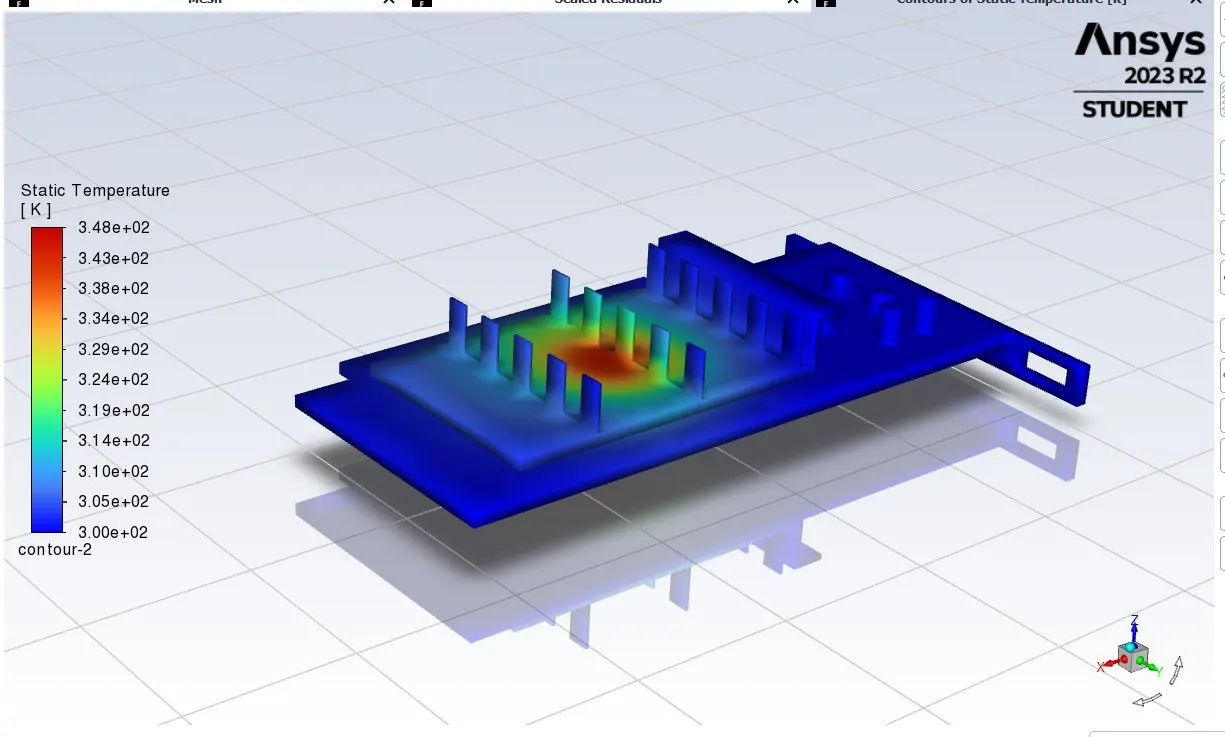
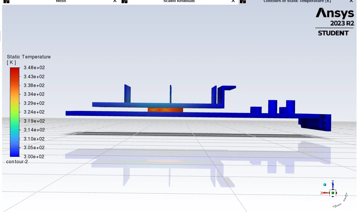
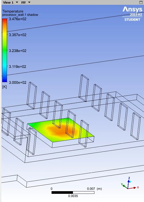
- The hotspot area is covered on the axis along the processor
RESULTS
Base wall temperature distribution
Air fins temperature distribution
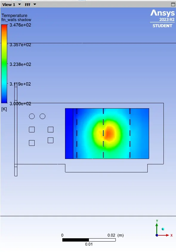
Top wall Processor temperature distribution
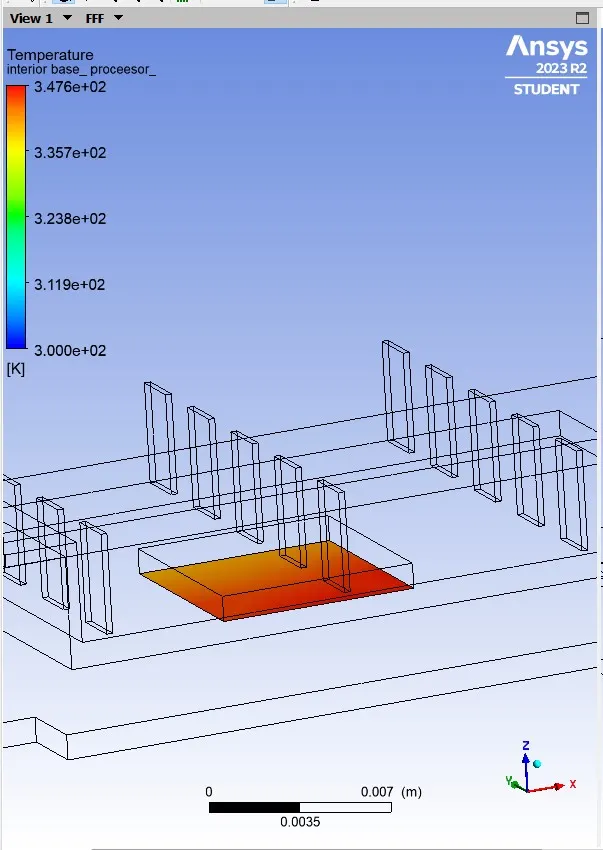
Bottom wall processor distribution
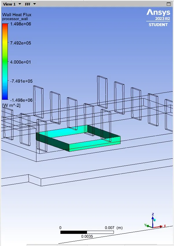
Processor wall heat flux
Scaled Residual
CONCLUSION
- As the mesh size increases , each mesh elements are keen and responsible for capturing the physical parameters while simulationg so that the temperature distribution on the graphics card on case 2 is well displayed after the simulation.
- Hotspot area remains same for case 1 and case 2 but the temperature distribution on the surface and on the wall is well potrayed on case 2 .