Week-7 Challenge: DC Motor Control
Ans 1a) MATLAB demo model named ‘Speed control of a DC motor using BJT H-bridge’ is explained below.
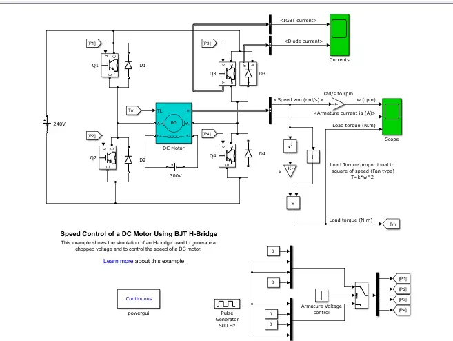
Detailed Explanation of the Above simulation: Here, 5Hp 240V, DC motor is used with fan torque simulated load which follows the square speed law. The H-bridge model is used having 4 IGBT(BJT based with inverse diode for freeheeling path)switches(Q1,2,3 & 4) to control DC motor operation in forward and reverse direction and also acting as a chopper to control the armature voltage of the motor and hence speed of this DC motor.
The gates of the 4 switches are provided by pulse generator through switch selector which decides the motor direction.
Working: The four switches Q1, Q2, Q3 and Q4 are connected such that when Q1 and Q4 is switched On, the motor will operate in forward direction and when Q2 abd Q3 is switched On, the motor will rotate in reverse direction. It is ensured in the gate pulse triggering design that either Q1Q4 or Q2Q3 is switched On and this is decided by Switch controlled by Armature voltage control block. There are two inputs to this switch. First Q1,Q4=0 and Q2Q3 connected to Pulse Gen and the Second input is Q1Q4 is connected to Pulse Gen and Q2Q3=0. The switch condition and armature control logic is shown below
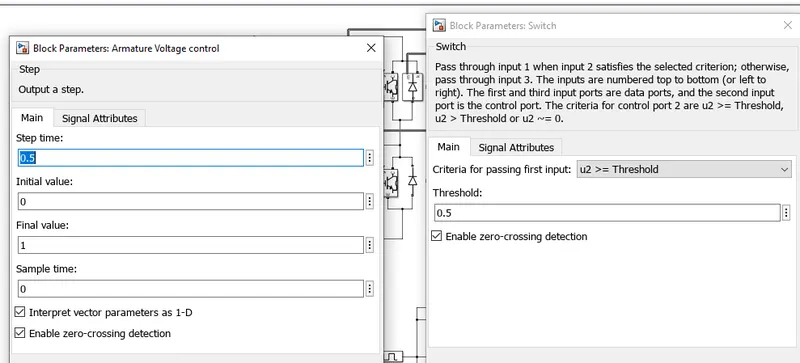
This means if the armature controlled voltage crosses 0.5 threshold, then only first input is taken otherwise second input. The armature voltage is kept 0 till 0.5s then 1. So for the first 0.5s of the simulation, second input of the switch will be active i.e, Q2Q3=0 and Q1Q4 gate is connected to pulse generator and thus the motor will operate in forward direction for the first 0.5s and then reverses after 0.5 till 1s of simulation.
Here free wheeling diodes are used as a safety purpose of converter/inverter circuit as when none of the switches are On, then these diodes provide the path for the flow of current and hence protecting the circuit from surge current.
The pulse generator is set for 500Hz and 75% duty cycle as shown
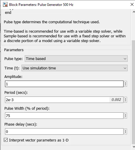
This will effectively chop the supply voltage to 180V from 240V.
Results: The scope results of this simulation is shown below:
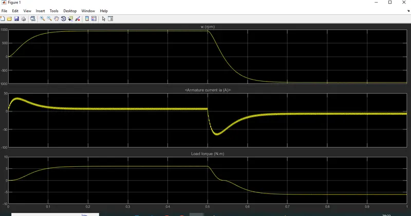
Speed initially increases to 0 to nearly 950 rpm upto 0.5 secs in Forward motoring action, then speed reduces to 0 rpm in forward dynamic braking action when armature voltage reverses in 5s and then speed increases from 0 to -900 rpm at upto 1 sec in Reverse motoring action.
As the load torque follows the speed square law thus the behavior of load torque variation is same as the motor speed.
Ans 1b.) The initial armature current shoot up can be explained as sudden application of high voltage of 180V across the motor armature. Now for this voltage motor is supposed to operate immediately at 950rpm appx theoretically. But in the practical scenario, due to inertia the speed can be attained immediately and thus to meet the load torque requirement, high current is demanded by the motor initially till the motor reaches the desired speed.
To reduce this overshoot of armature current, it is advisable to start the motor gradually in step with increasing armature voltage instead of directly applying the whole voltage.
Ans 1c) The four quadrant chopper DC motor drive, DC7 block contains DC motor, Converter and Controller together as shown below in one block to control the motor characteristics in all the four quadrants of operation.
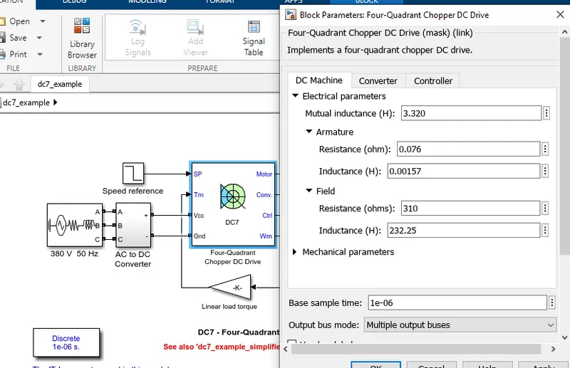
Its salient features and advantage over H- Bridge BJT control for DC Motor is discussed below
1. The Four-Quadrant Chopper DC drive can operates in all four modes namely Forward Motoring,Forward Braking, Reverse Motoring and Reverse Braking but H-bridge drive can only operate in 2 modes i.e, Forward and Reverse motoring.
2. In Four-Quadrant Chopper Regenerative Braking is possible, but H-bridge Regenerative Braking is not possible.
3. In Four-Quadrant Chopper Two PI regulator, first Speed Regulator followed by Current Regulator, is used to obtain electromagnetic torque needed to reach the desired speed, control the armature current and stabilize the system, but there is no PI regulator used in H-bridge model.
4. H-bridge is a Power electronic circuit that switches the polarity of Armature Supply voltage applied to the motor/load. In other case, Four-quadrant Chopper is electronic switch that is used to interrupt one signal under the control of another.
5. Thus, the Four-Quadrant Chopper drive is more efficient than the typical H-bridge DC motor drive.
Ans 2: Two quadrant Chopper or Type C chopper is obtained by connecting type-A and type–B choppers in parallel as shown below
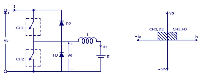
Working: Here, the average voltage will be always positive but the average load current can be positive or negative. The power flow can be from source to load in the first quadrant or from load to source in the second quadrant operation. The two choppers/switches should not be turned on simultaneously as the combined action my cause a short circuit in Source/supply . For regenerative braking and motoring these type of chopper configuration is used.
The matlab simulink model of 2-quad chopper is modelled as shown below
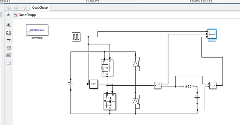
Simulation parameters are as follows:
It is simulated using Mosfet device with 50V source and 28V as load back EMF with Inductor of 1mH in series.
The Pulse generator is duty cycle is kept 50% with 0.02s time period.
The Simulation result includes Pulse Gen, Output Current and voltage is shown below
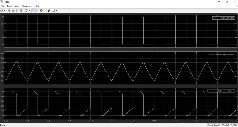
Conclusion/Result: We can see that the output voltage is always positive however current is positive for half cycle and negative of other half of switching cycle making it a two Quadrant Chopper. The maximum output voltage is 50V same as the source but the avegrage output voltage will be lesser than the 50V and hence acting as DC-DC chopper.
Ans 3: A brushless DC motor or BLDC motor is an electronically commuted DC Motor which does not have brushes unlike typical DC motor.
In brushless motors, permanent magnets rotate around a fixed armature and overcome the problem of connecting current to the armature. Commutation with electronics has a large scope of capabilities and flexibility. They are known for smooth operation and holding torque when stationary.
Operation: The basic working principle for the brushed DC motor and brushless DC motor are same i.e., the Lorentz force law except here the current carrying conductor is stationary while the permanent magnet moves.
Brushless DC motor has only two basic parts: rotor and the stator. The rotor is the rotating part and has rotor magnets whereas stator is the stationary part and contains stator windings. In BLDC permanent magnets are attached in the rotor and move the electromagnets to the stator. The high power transistors are used to activate electromagnets for the shaft turns. The controller performs power distribution by using a solid-state circuit.
When the stator coils are switched by a supply source, it becomes electromagnet and starts producing the uniform field in the air gap. Though the source of supply is DC, switching makes it an AC voltage waveform with trapezoidal shape. Due to the force of interaction between electromagnet stator and permanent magnet rotor, the rotor continues to rotate. Here the stator consists of three different windings whose switching sequence is shown below
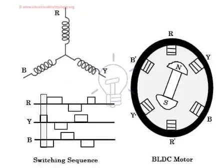
Hall sensors give shaft position feedback to the electronic controller unit(ECU) in BLDC. Based on this signal from sensor, the controller decides which coils to energize. Hall-effect sensors generate Low and High level signals whenever rotor poles pass near to it. These signals determine the position of the shaft.
The ECU energizes appropriate motor winding by turning PE switches to rotate the motor continuously. The figure below shows the typical drive circuit which consists of MOSFET bridge (acting as inverter bridge), ECU, hall effect sensor and BLDC motor.
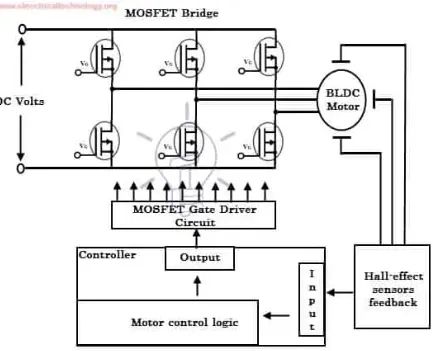
Here, Hall-effect sensors are used for position and speed feedback. The ECU can be a microcontroller unit or microprocessor or DSP processor or FPGA unit or any other controller. This controller receives these signals, processes them and sends the control signals to the MOSFET driver circuit.
In addition to the switching for a rated speed of the motor, additional electronic circuitry changes the motor speed based on required application. These speed control units are generally implemented with PID to have precise control. It is also possible to produce four-quadrant operation from the motor while maintaining good efficiency throughout the speed variations.