Project - Position control of mass spring damper system
Solution: The TF is obtained from the given Spring mass damper system and modelling is done:
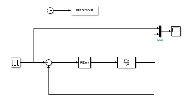
Note: The Modelling parameters are
Fixed step size of 0.01 with solver as ODE4(Runga-Kutta) and Input as Pulse generator of amplitude 1 and period 10s and width 50%.
>> PID_desgn
N =
0 0 0.2778
D =
1.0000 27.7778 111.1111
>> P
P =
-3.1416 + 5.4414i
-3.1416 - 5.4414i
>> K
K =
-257.8777 -77.3805
Note: The Kp and Kd obtained from the above pole placement design is not appropriate and hence we will assume the following Kp and Kd to start with:
>> Kp=wn^2
Kp =
111.1111
>> Kd=2*zeta*wn
Kd =
27.7778
>> Ki=0.0
Case1:
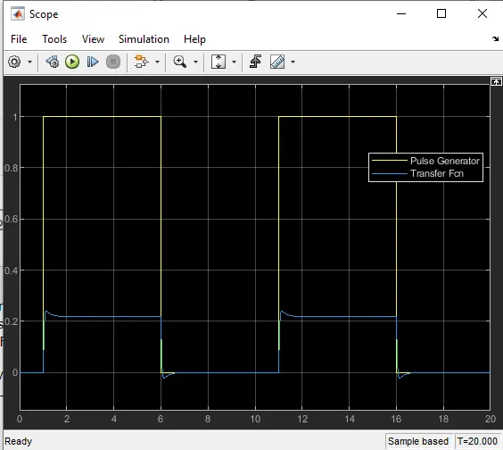
Result: The response Obtained is fast but has huge steady state error.
Case 2: Keeping Kp and Kd same, Ki is increased from 0 to 500.
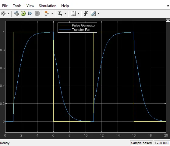
Result: The Steady state error is reduced but response is sluggish and underdamped.
Case 3: The Ki is increased to 1000.
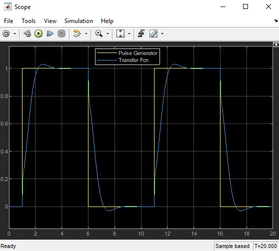
Result: The Steady state error is reduced to zero but response is faster and overdamped.
Case 4: The Ki is increased to 1500 to improve the response further.
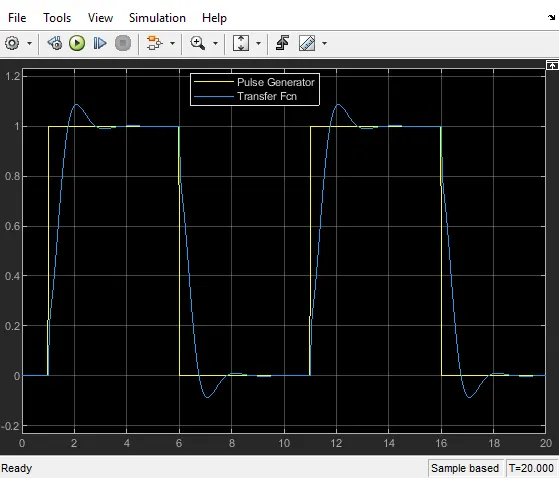
Result: The response is more faster but overshoot is near to 10%.
Case 5: The Ki is reduced to 1250 to reduce the overshoot<10%.
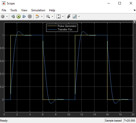
Conclusion: The optimum response is obtained with the controller gains as Kp=111.11, Kd=27.778 and Ki=1250. All the three important parameters like rise time, peak overshoot and steady error is best obtained at the above set PID controller gains.