Week-7 Challenge: DC Motor Control
1. A. Explain a MATLAB demo model named ‘Speed control of a DC motor using BJT H-bridge’.
Answer :-
BJT H-BRIDGE:
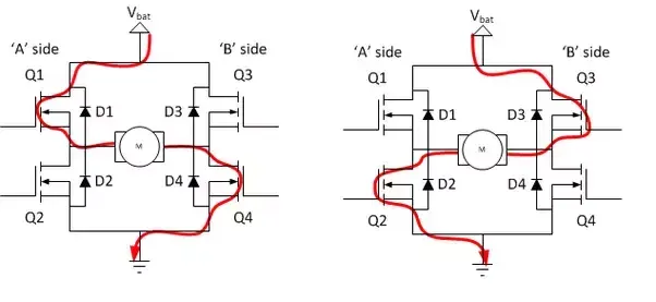
An H-bridge is an arrangement of transistors that allows a circuit full control over a standard electric DC motor. That is, an H-bridge allows a microcontroller, logic chip, or remote control to electronically command the motor to go forward, reverse, brake, and coast.
IGBT:
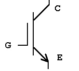
The insulated gate bipolar transistor (IGBT) is a semiconductor device with three terminals and is used mainly as an electronic switch. It is characterized by fast switching and high efficiency, which makes it a necessary component in modern appliances such as electric cars and variable frequency drives.
Its ability to turn on and off, rapidly, makes it applicable in amplifiers to process complex wave-patterns with pulse width modulation. It integrates an isolated gate using Field Effector Transistor to obtain a control input.
SIMULATION:
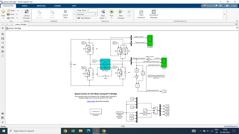
The Bipolar Junction Transistor (BJT) when used for power switching applications, operates as an IGBT. When it is conducting (BJT operating in the saturated region), a forward voltage Vf is developed between collector and emitter (in the range of 1 V). Therefore, the IGBT block can be used to model the BJT device.
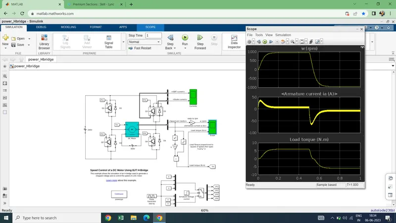
The IGBT block does not simulate the gate current controlling the BJT or IGBT. The switch is controlled by asignal. The DC motor uses the preset model (5 HP 24V 1750 rpm). It simulates a fan type load (where Load torque is proportional to square of speed).
The H-bridge consists of four BJT/Diode pairs (BJT simulated by IGBT models).
Two transistors are switched simultaneously as Q1 and Q4 or Q2 and Q3. When Q1 and Q4 are fired, a positive voltage is applied to the motor and motor runs in forward motion.
When Q2 and Q3 are fired, a negative voltage is applied to the motor runs in the reverse direction.
B.Comment on the armature current shoot-up from the scope results.
Answer:- Run the program
here,
as we lokk at into the rpm sped, the armature current is increases as the speed increases .After some time it moving in same speed and the armature current also being in same position. Tis happenes when Q! and Q4 are activated . After one cycle the Q2 and Q3 starts and the vehicle goes in reverse position or in braking position . There you can say that the armature current also changing to its negative direction and according to that the vehicle moves.
Speed of motor:
- Initially increases to 0 to nearly 900 rpm upto 0.5 secs(Forward motoring action takes place).
- Then speed reduces to 0 rpm(Forward dynamic breaking action takes place).
- Then speed increases from 0 to -900 rpm at upto 1 sec( Reverse motoring action takes place).
- Then reverse dynasmic breaking occurs(Not shown in scope).
Load torque of motor:
- Initially torque increase from 0 to 0.5 secs in forward motoring action.
- Then torque reduces to 0 Nm in forward dynamic breaking mode.
- Then torque increases in reverse direction in reverse motoring action upto 1 sec.
- Again torque reduce to zero.(Not shown in scope).
B) Armature current shoot up in motor.
Here the initial current shoot up is due to sudden increase in voltage which inurns regulated by duty cycle.In this case motor driven in 75% of duty cycle.(i.e) 0.75*240= 180 V.
Conclusion :- the rate of shoot up of armature current can be handled or decrease by changinf the duty cycle from 0 to 100 %.
C. Refer to the help section of ‘The Four-Quadrant Chopper DC Drive (DC7) block’. Compare it with the H-bridge model.
Answer:- 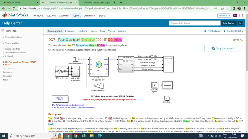
- here , in four quadrant chopper , IGBT is used here instead of BJT.
-
Comparisons:
- In DC7 chopper model speed controlled by varying current pulses from PI current controller and in H-brige model speed controlled by varying duty cycles voltages.
- Here regenerative breaking in occuring while in H-bridge model breaking is occured by changing polarity of current flow,dynamic breaking occurs in it.
- In four quadrant DC chopper model smoothing inductance is used for smooth increase and decrease in current flow which in turns controlling the motor speed smoothly,while in H-bridge it is not present.
- Here the operation is discrete and in H-bridge model it is continuous.
- Hence 4 quadrant DC choppers are used mostly in electric vehicles.
2. Develop a 2-quadrant chopper using simulink & explain the working of the same with the relevant results.
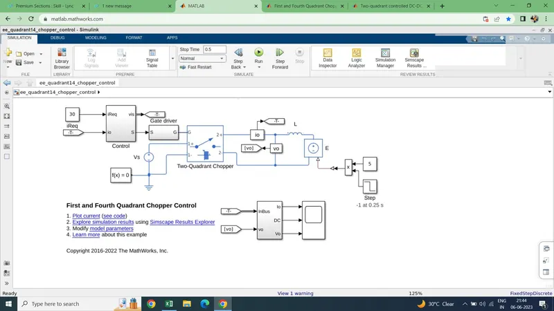
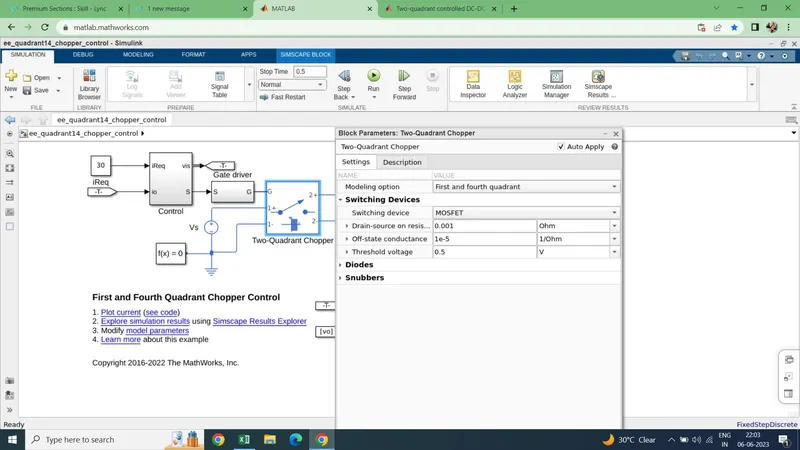
The Two-Quadrant Chopper block represents a two-quadrant controlled chopper for converting a fixed DC input to a variable DC output. The block contains two switching devices. Options for the type of switching devices are:
-
GTO — Gate turn-off thyristor. For information about the I-V characteristic of the device.
-
Ideal semiconductor switch — For information about the I-V characteristic of the device.
-
IGBT — Insulated-gate bipolar transistor. For information about the I-V characteristic of the device.
-
MOSFET — N-channel metal-oxide-semiconductor field-effect transistor. For information about the I-V characteristic of the device.
-
Thyristor — For information about the I-V characteristic of the device.
-
Averaged Switch — Semiconductor switch with an anti-parallel diode. The control signal port, G, accepts values in the
[0,1]interval. When the value at port G is equal to0or1, the averaged switch is either fully opened or fully closed, and it behaves similarly to the Ideal Semiconductor Switch block with an anti-parallel diode. When the value at port G is between0and1, the averaged switch is partly opened. You can then average the PWM signal over a specified period. This allows for undersampling of the model or using modulation waveforms instead of PWM signals.
Specify Chopper Quadrants
You can choose the quadrants where the Two-Quadrant Chopper operates. To select the quadrants, set the modelling parameter to either:
-
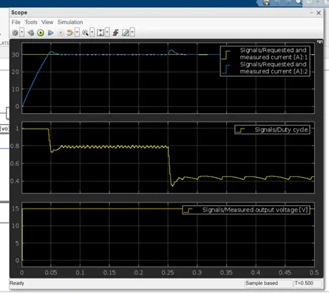
First and fourth quadrant. The figures show the equivalent circuit and the operation for the first- and fourth- quadrant model.here, In first quadrant when s1 and s2 is on and gate signal is triggered. Then the currents flows through the path s1-d2-d1 and the d2 acts like a free wheeling diode .
In second quadrant when s1 and s2 is off nd gate signal is triggered. Then the currents flows through the path s2-d2-d1 and the d1 acts like a free wheeling diode .
The result scope shows,
Speed increases in first quadrant as forward motoring action.Current is in positive direction.
Speed reduces at OFF time, So current get set back to source as regenerative breaking mode when CH2 open up.
Torque changes according to the speed crossing zero and produce negative torque while in second quadrant.
Thus result get justified.
3. Explain in a brief about operation of BLDC motor.
Answer :-
BLDC motor named as brushless dc motor having high effenciency than other types of motors.This motor is also known to be synchronous motor.
Construction:
Most of the motors are having brushes in their rotor as it transfers current into the rotor circuit.But here differently rotor is placed with permanent magnet.
The stator coil is wounded with coils,they are stationary but producing variable DC voltages for rotating the permanent magnet as changing the magnetic field of stator poles continuously.
The controlling of motor is by changing the magnitude and direction of current flowing through the stator windings.
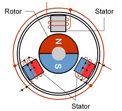
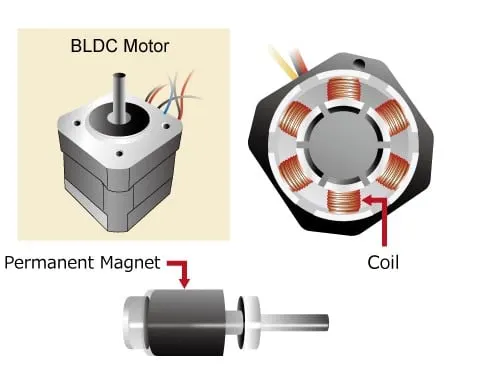
A BLDC motor with three coils on the stator will have six electrical wires (two to each coil) extending from these coils. In most implementations three of these wires will be connected internally, with the three
remaining wires extending from the motor body. Wiring in the BLDC motor case is more complicated than simply connecting the power cell’s positive and negative terminals. we will look more closely at how
these motors work in the second session of this series.
Operation of BLDC motor:
We can consider three winding trminal are comming out as U,V,W and their another ends are connected in single point as shown in below figure.The angle shift between two coils makes 120 degree.
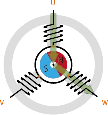
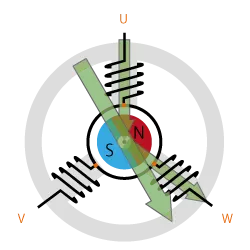
The current moves from U to W makes magnetizing the coils attracts the rotor consisting of permanent magnet makes moment as shown above to align with the resultant arrow(larger arrow).
North pole of magnet towards arrow mark of resultant arrow.
Rotation is maintained by continually switching the flux so that the permanent magnet is constantly chasing the rotating magnetic field induced by the coils. In other words, energizing of U, V, and W must be
continually switched so that the resultant flux keeps moving, producing a rotating field that continually pulls on the rotor magnet.
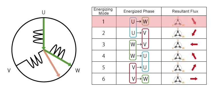
The above movement are acheived by continuous change in current direction over two poles of stator at single time.But this is slightly not continuous in their rotation.
This makes motor vibration and noice will be produced.
So, to attain smooth continuous rotation of rotor we have to control the current flow through all the three poles in same time.
As shown below we can acheive continuous change in current flow in all stator poles at same time in 120 degree phase shift.
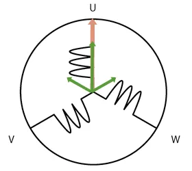
As we have seen, we drive BLDC motors by continually changing the directionality of the flux produced by the coils. The permanent magnets on the rotor continually chase the shifting rotating magnetic field,
causing the rotor to turn.
This is the working of BLDC motor.
Advantages of BLDC motor:
- One big advantage is efficiency, as these motors can control continuously at maximum rotational force (torque).
- Even small BLDC motors can deliver considerable power.
- BLDC motors can be controlled, using feedback mechanisms, to delivery precisely the desired torque and rotation speed.
- Reduce energy consumption and heat generation.
- BLDC motors also offer high durability and low electric noise generation.
- The sparks will not be produced as brushed motor between brushes and commutators.
Control of BLDC motor:
By using the inverter circuitry to also adjust the voltage into each coil, we can control the magnitude of the current.
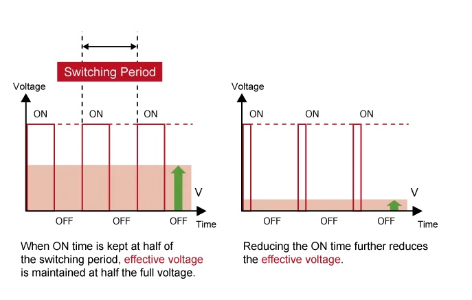
A typical way to adjust the voltage is with pulse width modulation (PWM). We alter the voltage by lengthening or reducing the pulse ON time ( “Duty cycle”: the ON time
expressed as a ratio of the ON+OFF switching interval). Increasing the duty cycle has the same effect as raising the voltage,reducing the duty cycle has the same effect as lowering the current.
PWM can be implemented using MPUs equipped with dedicated PWM hardware. While 120-degree conductiong control only requires two-phase voltage control.
sinusoidal control uses three-phase voltage control and is considerably more complicated as appropriate inverter circuitry is therefore essential for driving BLDC motors.