Week-6 Challenge: EV Drivetrain
Question no 1
The power converters used in the EV and HEV vehicles are as follows :-
Power converters Electronics :-
This electronic converters are the key elements in the EV drivetrain and HEV.In Electric and Hybrid Electric Vehicles (EV/HEV), the power electronic converters are considered as the key elements that interface their power sources to the drivetrain of the EVs. In order to design highly efficient converters for the EV’s power system, advanced DC/DC and DC/AC converters are required to adapt the output voltage and current levels with high power quality.
i) AC to DC converter:- The mostly power converter used are AC to DC converters. This converters are also called as rectifires which converts AC to DC.This converters supplies [ower from commercial power system to an on boaed high voltage battery. The downsized AC to DC converters used to controll the carbon di-oxide reduction in EV and PHEV systems.
The small representation of the Ac to Dc converters is shown below:-
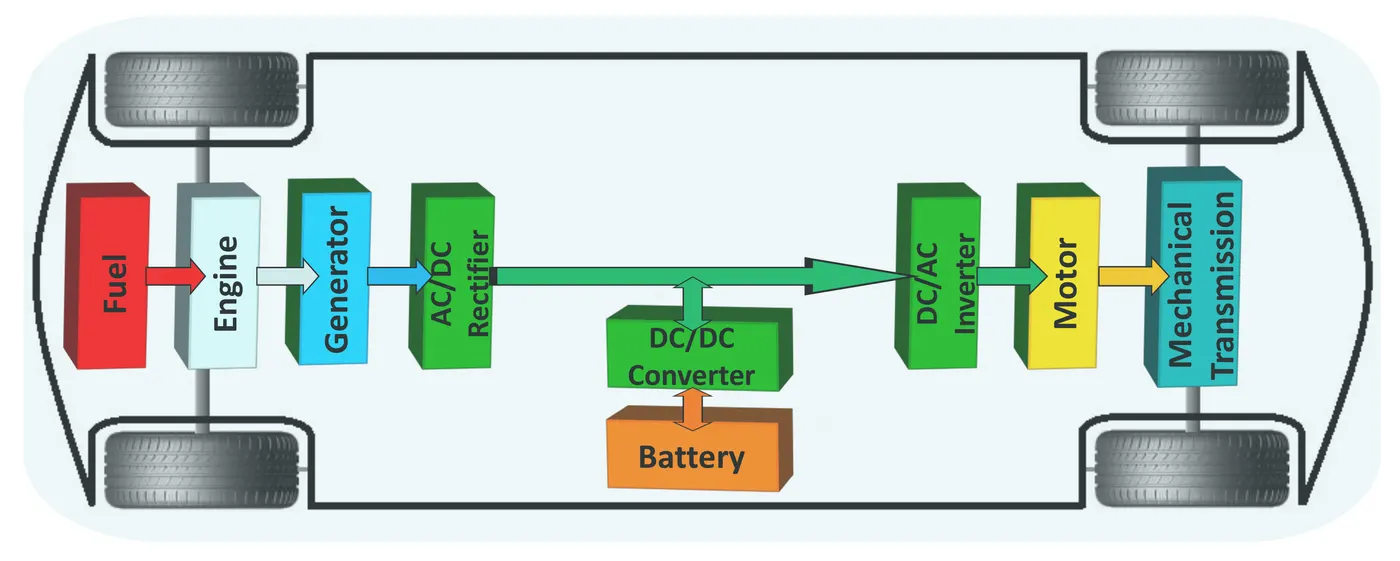
fig Ac to Dc converter in HEV vehicle.
ii) DC to DC convertes :-
The another top most power converters is used in EV and HEV vehicles are DC to DC converters.
This type of converters are also called as Chopper.IN electrical engineering a DC to DC converter is a category of power converters and it is an electric circuit which converts a source of direct current (DC) from one voltage level to another ,by storing the input energy temporarily and then the releasing that energy to the output at a different volatge. The storage may be in the magnetic field storage components (inductors,transformers or electric field storage components i.e capacitors). DC to DC converters are designed in such a way that it flows the power at one direction only.
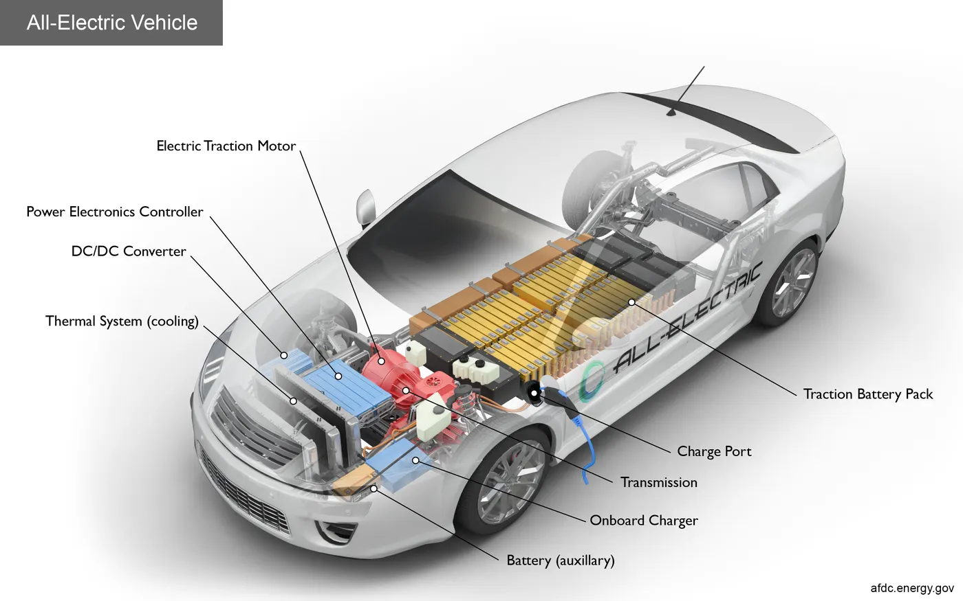
fig.2 represntaion of DC to DC converters
DC to DC power converters are manly divided into two parts
i)Step up ii) step down . from this converters we can either step up the DC voltage or step down the dc voltage as required.
iii) Inverters (DC to AC converters)
An inverterr is a device that converts DC power from the battery to Ac power in an electric vehicle motor. The inverter can change the speed at which the motor rotes by adjusting the frequency of AC current.
QUESTION NO 2
considering the diagram given :-
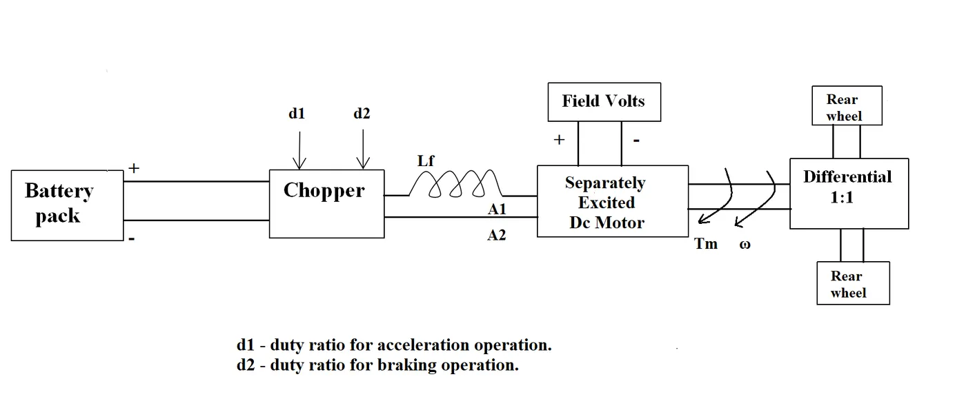
The other parameters of the electric vehicle is given below,
Motor and Controller Parameters:
Rated Armature voltage= 72 V
Rated armature current= 400 A
Ra= 0.5Ω, KΦ= 0.7 Volt second
Chopper Switching frequency= 400 Hz
The vehicle speed-torque characteristics are given by the below equation
Rated armature voltage is given – 72v
Duty cycle – 70%
Voltage – Va * Duty cycle
72 * 0.7 =50.4v
Torque equation –
w=V k Φ-Ra/ (k Φ)^2 *T
on arranging the equation becomes:-
T - k Φ /Ra * [V - k Φ* ω]
we known
k φ – 0.7
Ra- 0.5
T = (0.7/0.5)*[50.4-0.7* ω]
= 1.4*[50.4-0.7* ω] = 70.56 – 0.98 ω .....................(1)
Given

comparing the above equation with eqn (1)
T = Tv
70.56 – 0.98 ω = 24.7 + 0.0051 ω^2
0.0051 ω^2 + 0.98 ω + 24.7 - 70.56 = 0
0.0051 ω^2 + 0.98 ω – 45.86 = 0
on solving get the two value –
ω=38.91 / -231.071
speed cannot be negative so we select –
ω-38.91 rps
1 rps=9.552 rpm
therefore,
w=38.91*9.552 = 371.66=372
So steady state speed is – 372 rpm at 70% duty cycle.
QUESTION NO 3
We have taken values of Armature resistance Ra, K phi, voltage V, Torque T
Ra=0.5
k.phi=0.7
V=72 V
Torque as ramp input
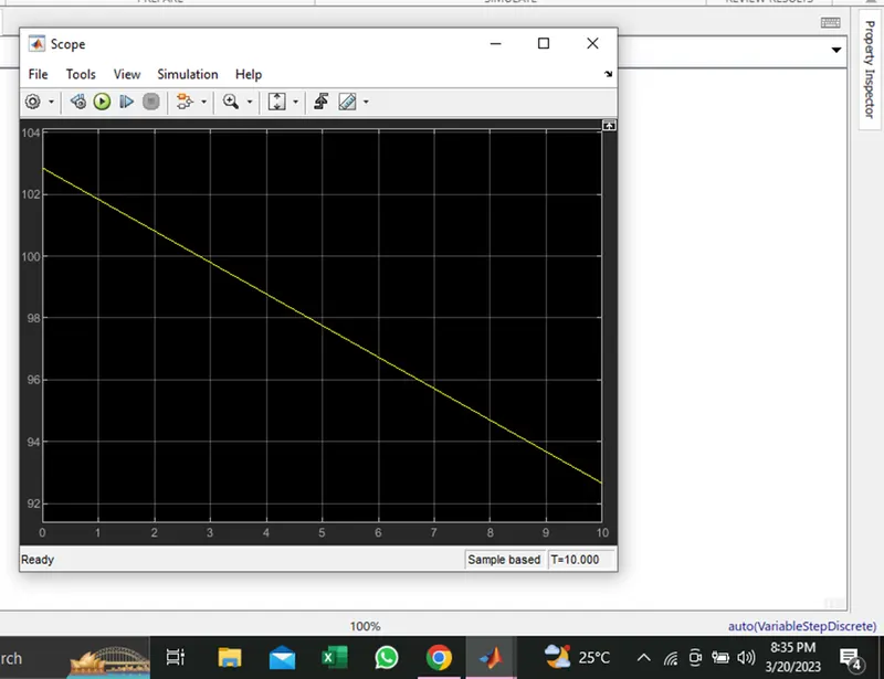
The model is shown below :-
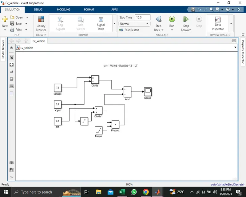
The scope output
QUESTION NO 4
In 1st paragraph he said:- With brushless machines, the rotor includes two or more permanent magnets that generate a DC magnetic field (as seen from the vantage point of the rotor). In turn, this magnetic field enters the stator core (a core made up of thin, stacked laminations) and interacts with currents flowing within the windings to produce a torque interaction between the rotor and stator. As the rotor rotates, it is necessary that the magnitude and polarity of the stator currents be continuously varied – and in just the right way - such that the torque remains constant and the conversion of electrical to mechanical energy is optimally efficient. The device that provides this current control is called an inverter. Without it, brushless motors are useless motors.
In 2nd paragraph with the positive side of induction motor:-
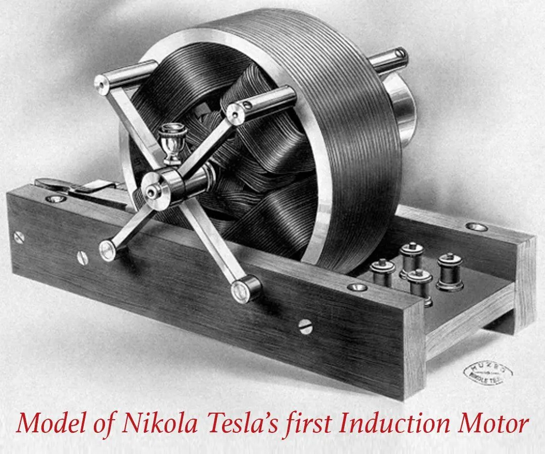
A forerunner of the 3-phase induction motor was invented by Nikola Tesla sometime before 1889. Curiously, the stators for the 3-phase induction motor and the DC brushless motor are virtually identical. Both have three sets of “distributed windings” that are inserted within the stator core. The essential difference between the two machines is with the rotor.
Unlike the DC brushless rotor, the induction rotor has no magnets – just stacked steel laminations with buried peripheral conductors that form a “shorted structure.” Currents flowing in the stator windings produce a rotating magnetic field that enters the rotor. In turn, the frequency of this magnetic field as “seen” by the rotor is equal to the difference between the applied electrical frequency and the rotational “frequency” of the rotor itself. Accordingly, an induced voltage exists across the shorted structure that is proportionate to this speed difference between the rotor and electrical frequency. In response to this voltage, currents are produced within the rotor conductors that are approximately proportionate to the voltage, hence the speed difference. Finally, these currents interact with the original magnetic field to produce forces – a component of which is the desired rotor torque.
In the above paragraph he said that how tesla had invented the induction motor without magnets and said the positive thoughts on them .
When a 3-phase induction motor is connected to utility type 3-phase power, torque is produced at the outset; the motor has the ability to start under load. No inverter is needed. (Were an inverter needed, Tesla’s invention would have been useless until sometime in the 1960s.) The fact that induction motors are directly compatible with conventional utility power is the main reason for their success. In contrast, a brushless DC motor produces no starting torque when directly connected to fixed frequency utility power. They really need the aid of an inverter whose “phase” is maintained in step with the angular position of the rotor.
While 3-phase induction motors have great utility, they also have some severe limitations. They cannot operate from DC; AC is a must. Shaft speed is proportionate to line frequency. Hence, when used with utility power, they are constant speed machines. Finally, when operated from utility power, they have limited starting torque and somewhat limited running peak torque capabilities, when compared to DC type machines.
He has ups and lows points for both brushless as well as induction motor like :-
Permanent magnets are expensive – something like $50 per kilogram. Permanent magnet (PM) rotors are also difficult to handle due to very large forces that come into play when anything ferromagnetic gets close to them. This means that induction motors will likely retain a cost advantage over PM machines. Also, due to the field weakening capabilities of induction machines, inverter ratings and costs appear to be lower, especially for high performance drives. Since spinning induction machines produce little or no voltage when de-excited, they are easier to protect.
I almost forgot: Induction machines are more difficult to control. The control laws are more complex and difficult to understand. Achieving stability over the entire torque-speed range and over temperature is more difficult with induction than with DC brushless. This means added development costs, but likely little or no recurring costs.
All in all... The question is what will happen as hybrids become more electrically intensive and as their performance levels increase?
His conclusion is that DC brushless drives will likely continue to dominate in the hybrid and coming plug-in hybrid markets, and that induction drives will likely maintain dominance for the high-performance pure electrics.
according to author his persepective that if hybrids become more electrically intensive and as their performance levels increase then induction drives will be more dominating in nature and can be used in future from Wallys perspective.