Project 1
1.Design a battery pack for a car roughly 150 Kw with 120 V. Use 3500 mAh 3.6V nominal NMC chemistry cell.
a. Design the battery pack configuration.
b. Draw the BMS topology for this battery pack
Answer:- Considering a battery back having specification
150 kw with 120 V .
cell specification :- 3500 mAh 3.6 V
Considering the series connection we need to connect the cells in series
Series connection = rated voltage /Nominal voltage =120/3.6=33.33=33 cells
Case1 No. of cells in series =33
Case2 No. of cells in series =34
Case1
Total voltage = nominal voltage * no of cells in series
= 3.6*33 = 118.8=119 V
case 2
Total voltage = nominal voltage * no of cells in series
=3.6*64= 122.4=122V
Here,
1. The nominal voltage should not exceed to load voltage .
Therefore ,we should take round off at lower value.
Therefore, No. of cells in series = 33
The output voltage can be adjusted using buck boost converter .
Parallel connection
total capacity =150 kw/120v=1250 Ah
No. of cells in parallel = required capacity /cell capacity
= 1250 Ah /3.5 ah= 357.14=357
Case 1 No.of cells in parallel =357
Case2 No. of cells in parallel=358
Case 1
Output capacity= cell capacity * no.of cells in parallel
=3.6*357=1285.2=1285 Ah
Case2
Output capacity= cell capacity * no.of cells in parallel
= 3.6*358=1288.8=1289
The total capacity cannot be less than required capacity .
Therefore ,the value is choosen to be lower = 1280 Ah
The current can be limited to required value by using current limiters.
The BMS topology is used according to how many cells are there in series
No of cells in series =33
Master Slave topology can be used to get output of 220 V. Because -
- More than 18 cells are used
- Less complicated than Modular
- Cost effective than Modular
- Gives proper output.
Here ,2 slave modules i.e Analog front end (AFE) are used to connect 33 cells in series and 1 MICROCONTROLLER.
Here we use Master slave topology.
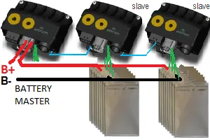
here we use 2 slave in that 1 slave connects only 18 cells in series and in 2nd slave we use only 15 cells in series .
Thats why we use only 2 slave and 1 master.
2.Build a 3S2P battery pack configuration with generic battery block using Matlab/Simulink.
3S2P battery pack configuration using simulink Model :-
The objective of this configuration is to connect the batteries in 3S2P configuration in Matlab/Simulink. That 3 cells should be connected in series and 2 cells are connected in parallel.
Total numbar of cellls in battery pack =No. of cells in series * NO. of cells in parallel
= 3*3=6 cells
Step1 : Arrangement of 6 cells
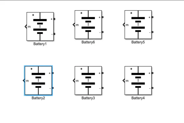
fig 1 Arrangement of 6 cells
Step 2 : Series connection
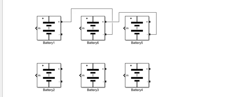
here we connect the cells in series connection i.e We connect positive of first battery to the negative terminal of next battery as shown in figure .
Step 3 : Parallel connection :-
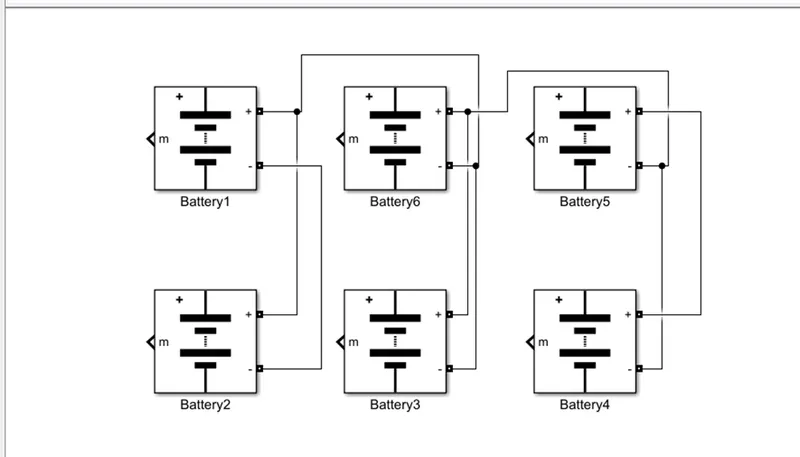
fig 3 Parallel connection
In parallel connection we havee to connect same terminals of the battery column wise .
First battery s positive terminal is connected to the Battery 2 positive terminal and likewise negative to negative of battery 1 to battery 2 is connected as shown .
So , you can see that whole series and parallel connection are shown in fig 3.
Model Explanation :-
The fig . 4 shows 3S2P battery configuration pack simulink model. The voltage measurement block is connected across the battery pack to measure the battery pack voltage .The scope output is used for SOC , current and voltage.The controlled signal (controlled current source ) is given as a load to the battery pack .The constant block is determined with the battery capacity and it is given to controlled current source.
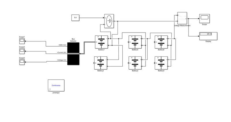
fig 4 Complete Model of 3S2P battery configuration
The parameters given inside the battery is given below :-
| Sr. No. | battery parameters | Value |
| 1 | Nominal voltage of cell | 7.2 V |
| 2 | Rated capacity of cell | 5.4 Ah |
| 3 | Maximum voltage of cell | 8.3 V |
Nominal voltage of battery pack =Nominal voltage * No. of cells in series
=7.2*3= 21.6 V
Rated capacity of a battery pack =Rated capacity *No. of cells in parallel
=5.4*2=10.8 Ah
The model is for an 21.6 V ,10.8 Ah battery.
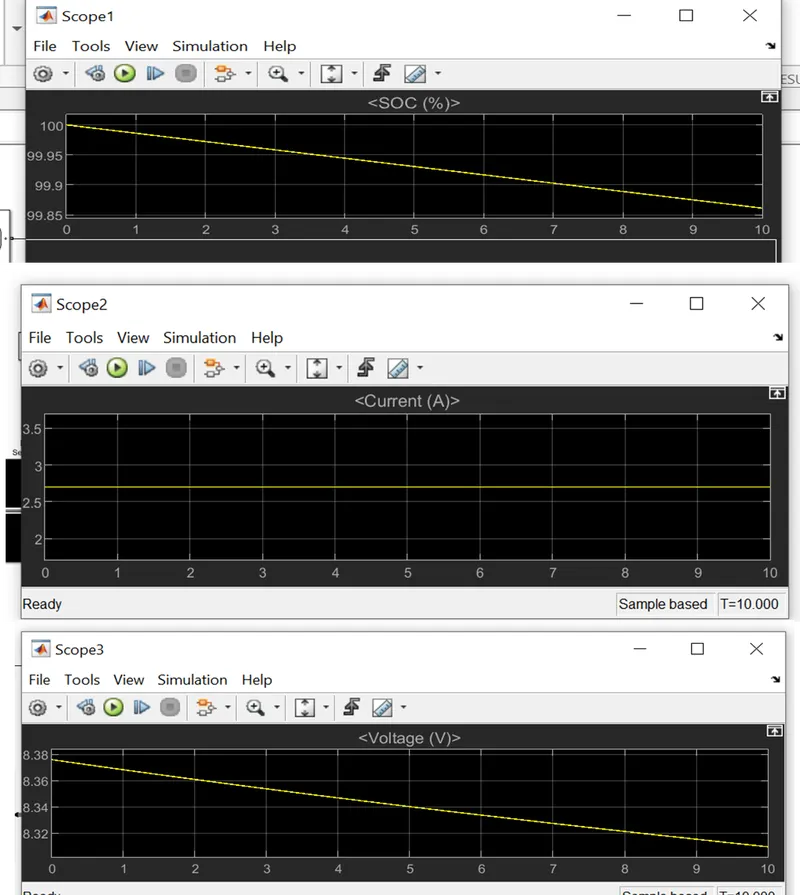
Fig. single battery output SOC, Current and Voltage
The scope 1 , scope 2 and scope 3 shows
Plot1 : SOC (state of charge ) is started to reduce from 100 % to 99.85 % shown correspomding to load given .
Plot 2 : The current signal is determined by the load and the decrease in current due to regenerative braking .
Plot 3 : The voltage is around is 8.3 V
overall battery capacity of battery pack =Max. voltage of battery * no. of cells in series
=8.3*3=24.9 V
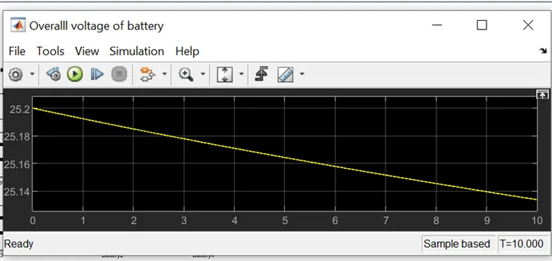
fig. Overall voltage of battery pack