Week-7 Challenge: DC Motor Control
Answer 1.
Part A.
the H- bridge basic diagram is shown below-
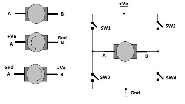
Here four switches SW1, SW2, SW3, SW4 are operating in the the manner that two switches are on at the same time and two switches are off but the On switches are not of the same branch.
as
when SW1, SW4 are then circuit is completed from +V to SW1 to Motor with A +ve and B -ve then to SW4 and grounded. the speed roataion of motor in this case is in forward direction and similerly when Switches SW2 and SW3 is on motor rotates in reverse direction.
Description
The Bipolar Junction Transistor (BJT), when used for power switching applications, operates as an IGBT
(Insulated Gate Bipolar Transistor).
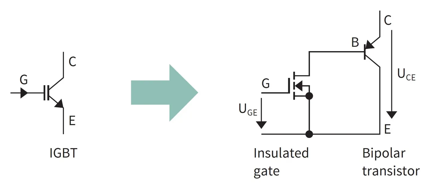
IGBT as switch
when Vge>0 or higher the critical volatage then IGBT is On state otherwise in Off state.
When it is conducting (BJT operating in the saturated region), a forward voltage Vf is developed between collector and emitter (in the range of 1 V). Therefore, the IGBT block can be used to model the BJT device.
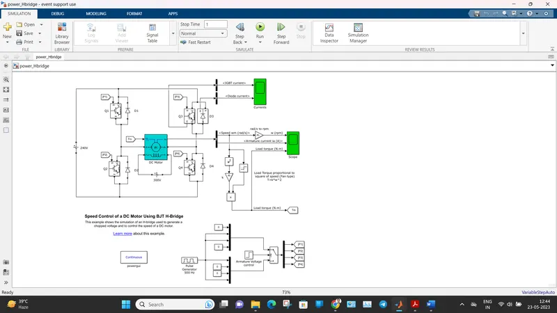
The IGBT block does not simulate the gate current controlling the BJT or IGBT. The switch is controlled by a Simulink® signal (1/0). The DC motor uses the preset model (5 HP 24V 1750 rpm). It simulates a fan type load (where Load torque is proportional to square of speed). The armature mean voltage can be varied from 0 to 240 V when the duty cycle (specified in the Pulse Generator block) is varied from 0 to 100%.
The H-bridge consists of four BJT/Diode pairs (BJT simulated by IGBT models). Two transistors are switched simultaneously: Q1 and Q4 or Q2 and Q3. When Q1 and Q4 are fired, a positive voltage is applied to the motor and diodes D2-D3 operate as free-wheeling diodes when Q1 and Q4 are switched off. When Q2 and Q3 are fired, a negative voltage is applied to the motor and diodes D1-D4 operate as free-wheeling diodes when Q2 and Q3 are switched off.
Simulation
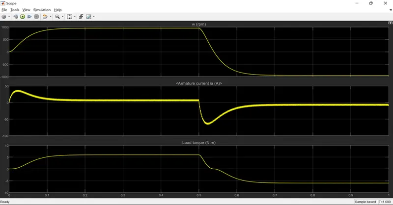
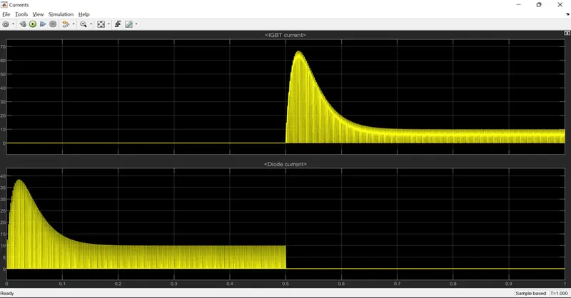
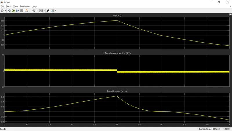
The motor starts in the positive direction with a duty cycle of 75% (mean DC voltage of 180V). At t= 0.5 sec., the armature voltage is suddenly reversed and the motor runs in the negative direction.
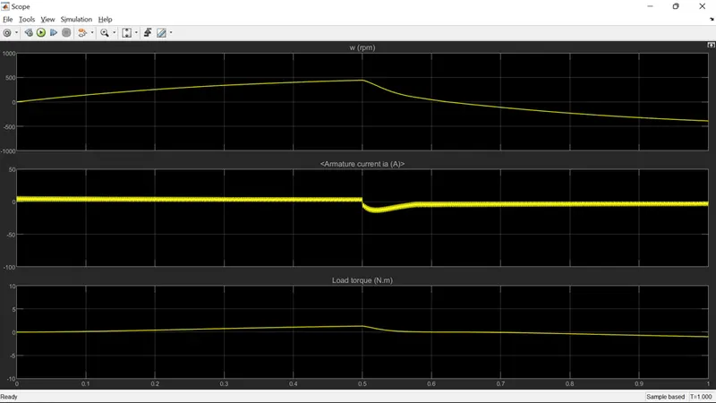
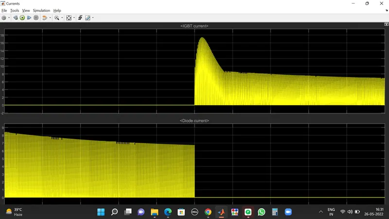
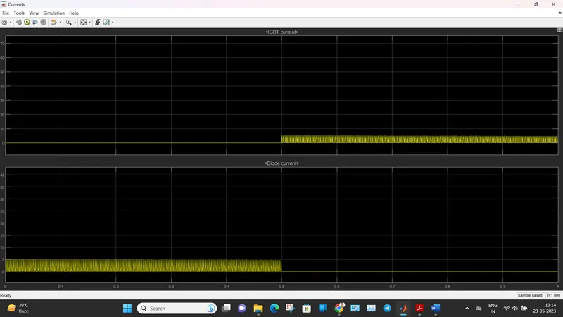
'Scope' shows motor speed, armature current and load torque and 'Currents' shows currents flowing in BJT Q3 and diode D3.
Duty Cycle of 75% Response
Duty Cycle of 50% Response
The results below with 50% duty cycle show the reduction in speed armature current and load torque as terminal voltage got reduced with duty cycle hence the output also got reduced.
Similarly a reduction in IGBT and diode currents can be observed.
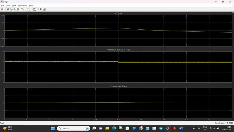
Duty Cycle of 30% Response
Part B.
1. In above 2 results we observe the armature current in both cases we can see a shoot up in the armature current as switching takes place.
2. This shoot up in armature current is reduced in the second case (50% Duty cycle).
3. So to get a smooth armature current duty cycle needs to be adjusted to its min value possible.
4. Around 40% duty cycle the shoot up in armature current during switching is very small and the current is almost constant and smooth as shown below.
Part C.
The Four-Quadrant Chopper DC Drive (DC7) block is shown below-
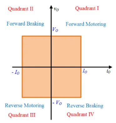
A 4 quadrant chopper can operate a DC motor in all 4 operating modes as given below
Forward Motoring (1st Quadrant) : Speed +ve, Torque +ve, Power +ve
Reverse Braking (2nd Quadrant) : Speed -ve, Torque +ve, Power -ve
Reverse Motoring (3rd Quadrant) : Speed -ve, Torque -ve, Power +ve
Forward Braking (4th Quadrant) : Speed +ve, Torque -ve, Power -ve
The Four-Quadrant Chopper DC Drive (DC7) block
The 200 HP DC motor is separately excited with a constant 150 V DC field voltage source. The armature voltage is provided by an IGBT converter controlled by two PI regulators. The converter is fed by a 515 V DC bus obtained by rectification of a 380 V AC 50 Hz voltage source. In order to limit the DC bus voltage during dynamic braking mode, a braking chopper has been added between the diode rectifier and the DC7 block.
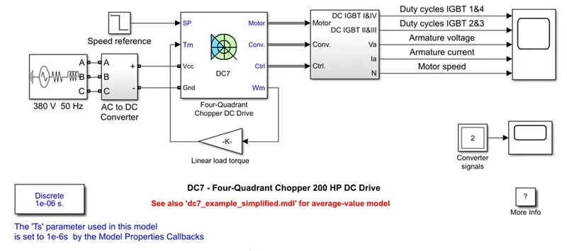
The first regulator is a speed regulator, followed by a current regulator. The speed regulator outputs the armature current reference (in p.u.) used by the current controller in order to obtain the electromagnetic torque needed to reach the desired speed. The speed reference change rate follows acceleration and deceleration ramps in order to avoid sudden reference changes that could cause armature overcurrent and destabilize the system. The current regulator controls the armature current by computing the appropriate duty ratios of the 5 kHz pulses of the four IGBT devices (Pulse Width Modulation). For proper system behavior, the instantaneous pulse values of IGBT devices 1 and 4 are opposite to those of IGBT devices 2 and 3. This generates the average armature voltage needed to obtain the desired armature current. In order to limit the amplitude of the current oscillations, a smoothing inductance is placed in series with the armature circuit.
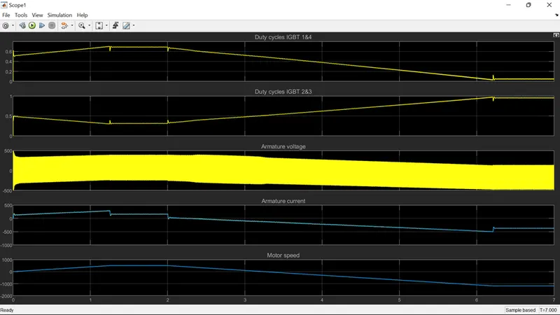
Comparison between H-Bridge and 4-Quadrant chopper
|
Four-Quadrant Chopper DC Drive |
H-bridge model |
|
To change the motor direction the polarity is changed |
To change the motor direction the current signal has to be interrupted. |
|
It has broader torque and power output ranges |
It uses single pulse generator which gives narrow torque and power output range. |
|
It operates in all four mode of operations |
It operates in only two modes of opeartions. |
|
Up to 400V can be achieved. |
Up to 350V can be achieved. |
|
In this the current has chopped values. |
In this the current has continuous values. |
|
Regenerative braking is possible |
Regenerative braking is not possible |
Answer 2.
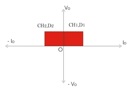
Circuit Diagram of Type C chopper and its two quadrant operation is shown below.
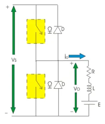
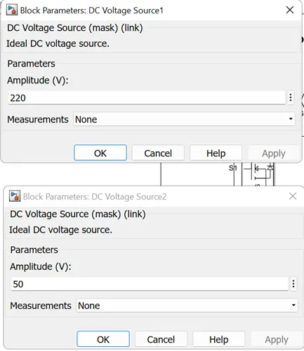
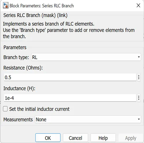
A simple type C (1st & 2nd Quadrant) chopper is simulated below. Here two MOSFETs and two Diodes are used. A series RLC branch is connected in series with a 12V battery which works as the load and back emf (110V) in the motor.
Gate pulse generator is used to get the gate pulses required and as shown below G1 and G2 are opposite to each other to prevent switching S1 and S2 ON at the same time. A DC supply voltage of 220V is given as the input to the converter circuit. Here the duty cycle is 50%.
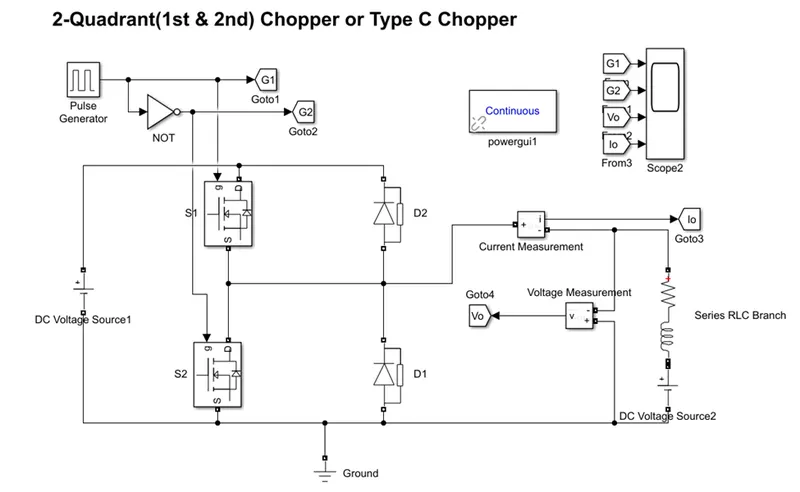
Simulation results are showing the gate pulses (G1 & G2) and the output voltage (Vo) and output current (Io).
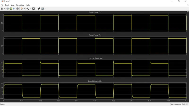
From the above result it can be observed that the voltage across the load is always positive but the current is both positive and negative, which confirms the 2-quadrant operation of chopper circuit.
Answer 3.
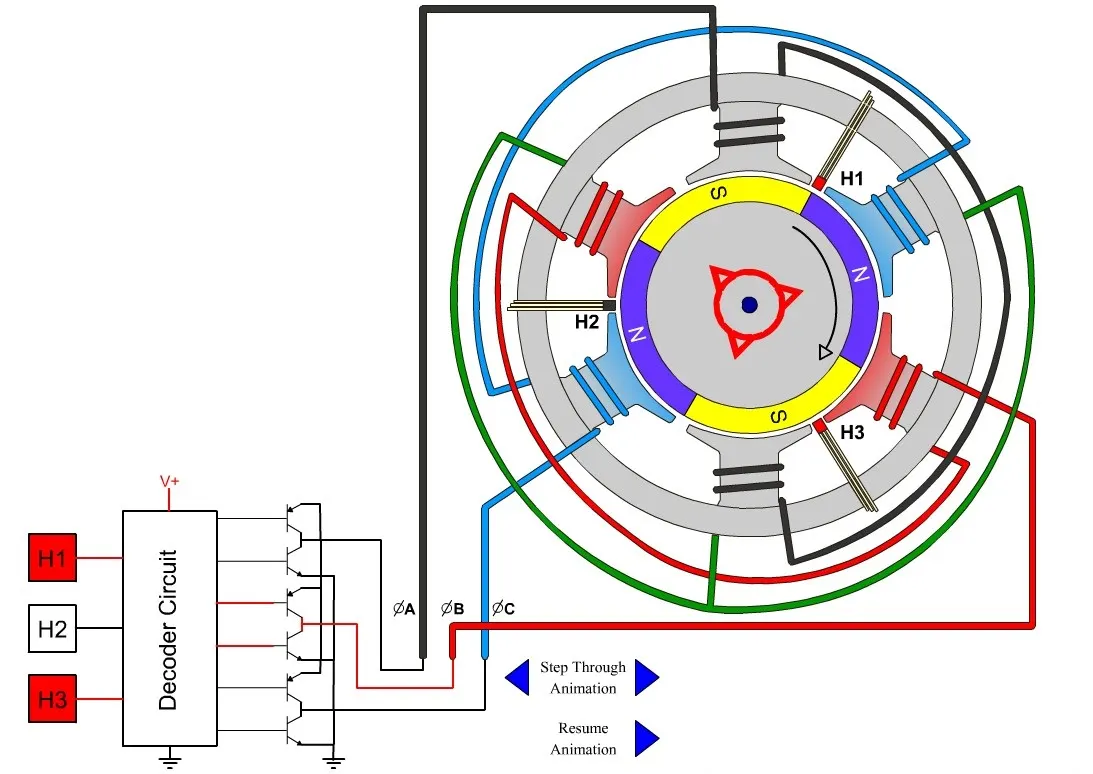
Brushless DC motor is a type of DC motor which as the name suggests is brushless.
As their name implies, brushless DC motors do not use brushes. With brushed motors, the brushes deliver current through the commutator into the coils on the rotor and there is fixed voltage drop also in the brushes. So how does a brushless motor pass current to the rotor coils? It doesn’t—because the coils are not located on the rotor. Instead, the rotor is made of the permanent magnet, the coils are instead fixed in place on the stator. Because the BLDC Motors do not have coils so there is no need for brushes and a commutator.
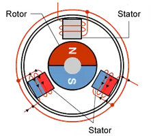
(Source Internet)
(Source Internet)
With a BLDC motor, it is the permanent magnet that rotates; rotation is achieved by changing the direction of the magnetic fields generated by the surrounding stationary coils which are energised by with the help of a controller circuit in the way that preceeding and succedding poles of rotor got attaraction and repulsion accordingly. To control the rotation, you adjust the magnitude and direction of the current into these coils.
Since the rotor is a permanent magnet, it needs no current, eliminating the need for brushes and commutator. Current to the fixed coils is controlled from the outside.
Advantages of BLDC Motors
1. One big advantage is efficiency, as these motors can control continuously at maximum rotational force (torque). Brushed motors, in contrast, reach maximum torque at only certain points in the rotation. For a brushed motor to deliver the same torque as a brushless model, it would need to use larger magnets. This is why even small BLDC motors can deliver considerable power.
2. The second big advantage—related to the first—is controllability. BLDC motors can be controlled, using feedback mechanisms, to deliver precisely the desired torque and rotation speed. Precision control in turn reduces energy consumption and heat generation, and—in cases where motors are battery powered—lengthens the battery life.
3. BLDC motors also offer high durability and low electric noise generation, thanks to the lack of brushes. With brushed motors, the brushes and commutator wear down as a result of continuous moving contact, and also produce sparks where contact is made. Electrical noise, in particular, is the result of the strong sparks that tend to occur at the areas where the brushes pass over the gaps in the commutator. This is why BLDC motors are often considered preferable in applications where it is important to avoid electrical noise.
Ideal Applications for BLDC Motors
Because of their efficiency and longevity, they are widely used in devices that run continuously. They have long been used in washing machines, air conditioners, and other consumer electronics; and more recently, they are appearing in fans, where their high efficiency has contributed to a significant reduction in power consumption.
They are also being used to drive vacuum machines. In one case, a change in the control program resulted in a large jump in rotational speed—an example of the superlative controllability offered by these motors.
BLDC motors are also being used to spin hard disc drives, where their durability keeps the drives operating dependably over the long term, while their power efficiency contributes to energy reduction in an area where this is becoming increasingly important.
Future Applications for BLDC Motors
We can expect to see BLDC motors used in a wider range of applications in the future. For example, they will probably be widely used to drive service robots—small robots that deliver services in fields other than manufacturing. One might think that stepper motors would be more suitable in this type of application, where pulses could be used to precisely control positioning. But BLDC motors are better suited to controlling the force. And with a stepper motor, holding the position of a structure such as a robot arm would require a relatively large and continuous current. With a BLDC motor, all that would be required is a current proportional to the external force—allowing for more power-efficient control. BLDC motors may also be replacing simple brushed dc motors in golf carts and mobility carts. In addition to their better efficiency, BLDC motors can also deliver more precise control—which in turn can further extend battery life.
BLDC motors are also ideal for drones. Their ability to deliver precision control makes them especially suited for multirotor drones, where the drone’s attitude is controlled by precisely controlling the rotational speed of each rotor.
In this session, we have seen how BLDC motors offer excellent efficiency, controllability, and longevity. But careful and proper control is essential to taking full advantage of these motors’ potential. In our next session, we will look at how these motors work.