Week-6 Challenge: EV Drivetrain
Answer 1.
Power Converter Circuits- Power converter circuits are those semiconductors based power electronics circuits which controls, converts power from DC to DC by choppers, DC to AC by inverters, AC to DC by rectifiers, AC to AC by AC voltage controllers and also can convert frequency of AC voltage by cyclo converters.
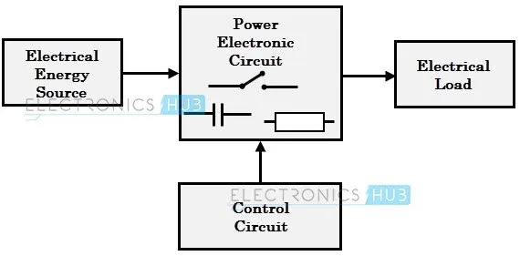
(Source Internet)
Type of Power Coverter circuits involved in Electrical Vehicle and Hybrid Electrical Vehicle is Given Below-
Rectifiers- This type of circuits converts AC power into DC power and hence is used for the charging purpose of batteries packs. they are two types- Half wave rectifier and Full wave rectifiers. Further classifiaction is based on the type of load half wave and full wave rectifiers with R Load, R-L Load, R-L-E Load. for the charging of battery we can consider it as a R-E load.
Full Wave Bridge type rectifier for Battery Charging
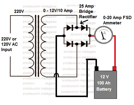
(Source Internet)
Inverter- It converts DC supply into AC supply so that battery power can be used by Induction motors. it is of two types
-
Voltage Source Inverter VSI− The voltage source inverter has DC source voltage as a input voltage that is the DC voltage has limited or zero impedance at the inverter input terminals.
-
Current Source Inverter CSI − A current source inverter is supplied with a variable current from a DC source that has high impedance. The resulting current waves are not influenced by the load.
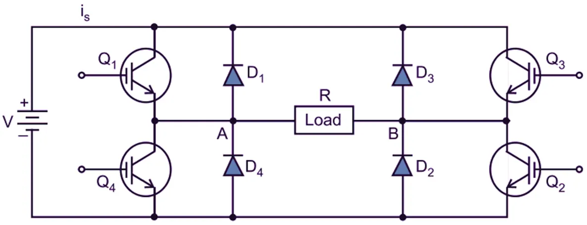
(Source Internet)
Choppers- This are DC to DC converters used for the controlling of DC voltage for the battery charging and many other purposes.
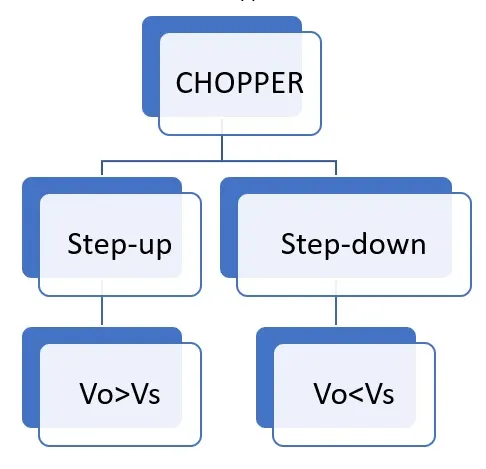
(Source Internet)
(Source Internet)
Cyclo-converter- This type of converter change the frequency of the Supply voltage and so by doing this we can change speed of induction motors.
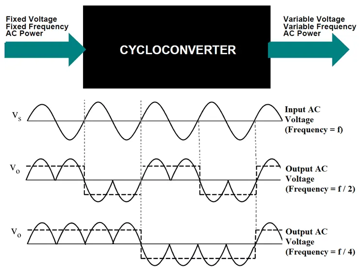
(Source- Internet)
Answer 2.
Answer 3.
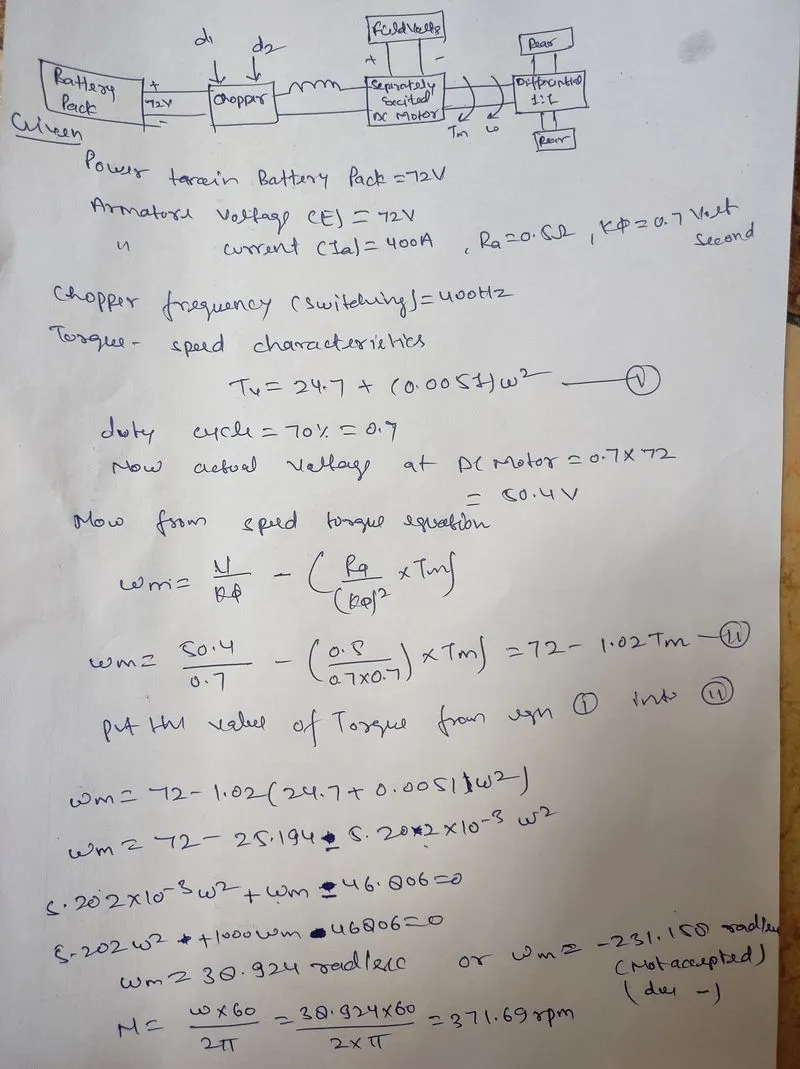
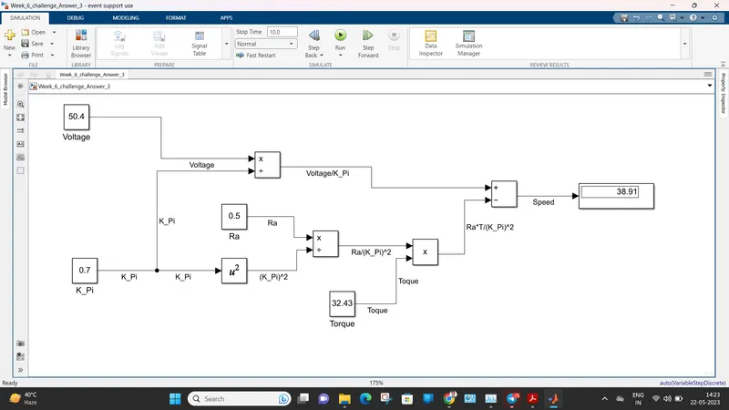
The data of torque, Ra, K_pi, V etc. are taken from answer no 2. we can also give it from user also.
Answer 4.
Reffering to the blog of Induction Versus DC brushless motors by Wally Rippel, Tesla we can say about authors prospective-
About DC Brushless Motor-
1. The stator of BLDC Motor is made of thin and staked laminations and rotor have two or more permanent magnets.
2. Basic principle of operation is the interlocking of Stator and rotor magnetic poles but as rotor have permanent magnets so its poles can not be changed.
3. So we need a controll circuit on the stator winding which changes the magnetic polarity of the stator winding according to the preceding and succeeding poles of rotor.
4. That control circuit is called an inverter circuit which can control polarity of the stator winding in the way that with the interaction of stator and rotor field an electromangetic torque is generated.
About 3 Phase Induction Motor-
1. Stator of BLDC and 3 Phase induction motor is same in construction and also 3 phase winding which displaced 120 degree in mechanical angle in the stator is used.
2. the rotor of 3 Phase induction motor is either wound rotor in which winding is done in rotor slots made of thick and staked laminations, or squirrel cage in which conductors bars with some skewing angle is inserted in the rotor made of thick and staked laminations.
3. when the stator magnetic filed interact with the rotor an emf is induced which further produced and electric current in the windind (rotor winding/bars are short circuited) and so an electromagnetic force/torque is produced which try to catch stator magnetic field.
4. It does not require a inverter circuit to start.
Conclusions-
Still no one can say who is winner but BLDC is used more in market rather than 3 Phase induction motor because of its some limitations.