Week-7 Challenge: DC Motor Control
TASK-1-A:
Speed control of a DC motor using BJT H-bridge:
The speed control of a DC motor is possible by varying input voltage.
BJT :
Bi-polar junction transistor(BJT) when used for power switching applications , operates as an (insulated gate bi-polar transistor)IGBT. IGBT is used in high power application due it has high voltage and current withstand capability. Its switching frequency is 10kHz. It has three terminals (Collector, Emitter, Gate). Which is voltage controlled device.
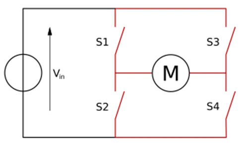
H-bridge: it is an Electronic circuit that switches the polarity of the applied voltage to the load. These circuit used for the application of forward and reverse operation. Its name derived from its common schematic diagram with four switching elements configured as the branch of a letter ‘’H’’ .
Simulink model:
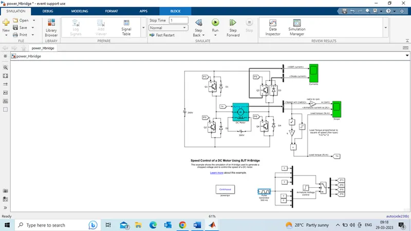
In these model following blocks are used .
DC machine, IGBT, diode, Dc voltage source, pulse generator, Bus selector, Mux, Demux, switch
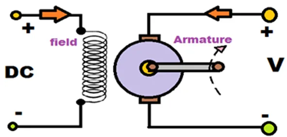
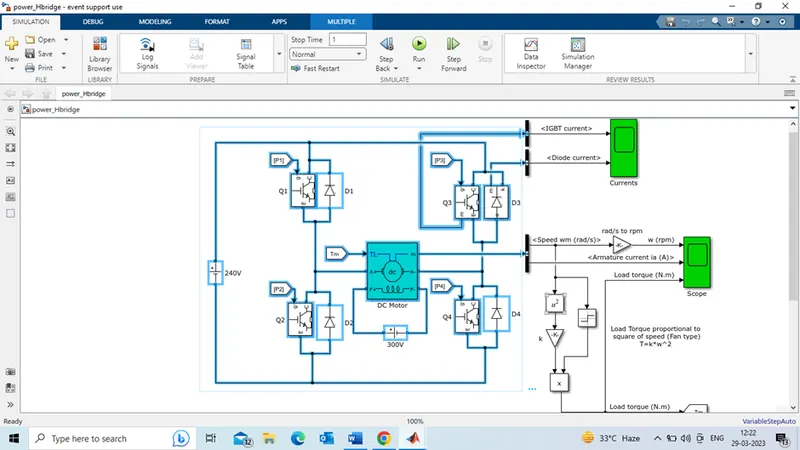
Here, Dc machine have two dc voltage source one is for field coil 300V and another for armature coil 240V. the DC machine is a separately excited.
H-bridge:
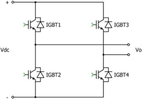
Pulse generator control signal is applied to gate terminal of IGBT to control voltage flowing through the circuit. Voltage 240 V is applied to the Collector terminal of the IGBT.
When the pulse generator gives on control signal to the gate terminal of IGBT, IGBT switch is on and current flows through the collector to emitter. Same as when IGBT receives OFF control signal from Pulse generator it cut off the flow of Current through it.
Pulse generator gives on/Off control signal based on the duty cycle. Here we take the 75% of pulse width w.r.t time. therefore 75 % of 240v to certain time is on control signal and then Off for 25%.
Operation: Highlighted part in below.
Forward direction:
Initially, Q1 and Q4 Receive the on-control signal from Pulse generator, then current flows through the +Vdc->Q1->+A-> -A->Q4-> -Vdc, Current flow in positive direction and voltage also shown in +Vdc to -Vdc (positive polarity). When the IGBT1 and IGBT4 are off, the current conducts through the free-wheeling diodes D3 and D2. Voltage polarity is changed -A to +A.
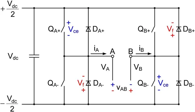
Example: Q1 is QA+, Q2 is QA-, Q3 is QB+ and Q4 is QB- . here shows the direction of current(iA) from QA+ -> A –> B-> QB- which is positive polarity. After QA+ and QB- off Free-wheeling diodes are DB+ and DA- are conduct the flow of current.
Reverse direction:
While in Off control from the pulse generator the flow direction is reverse. +Vdc->Q3-> -A->+A->Q2->-Vdc. Now the polarity of current flow direction is negative. Negative current is appeared across this cycle.
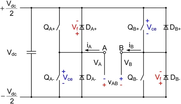
Example: Q1 is QA+, Q2 is QA-,Q3 is QB+ and Q4 is QB- . here shows the direction of current(iA) from QB+ -> B –> A-> QA- which is negative polarity. After QB+ and QA- off Free-wheeling diodes are DA+ and DB- are conduct the flow of current.
TASK-1-B:
Armature current: the speed control of Dc motor is achieved by varying the armature voltage by using power electronics. The variation in voltage is carried by switching on and off the voltage to the circuit. When the circuit is on , the current flows in positive direction and when the circuit is off , the current flows in negative direction.
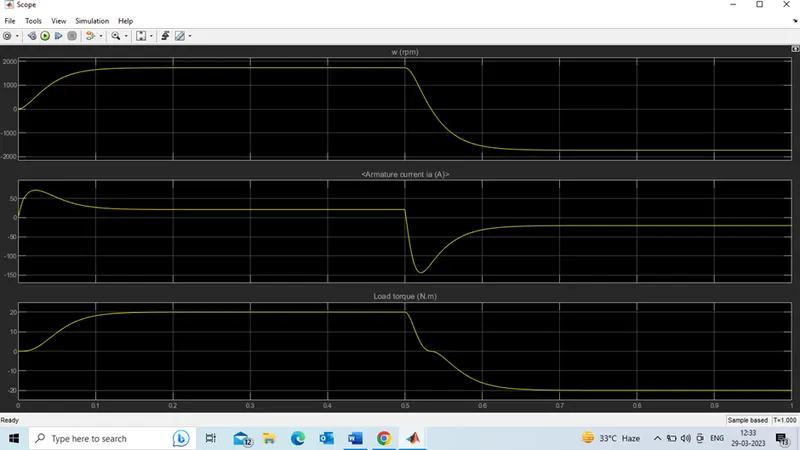
From the output, the armature current is positive (0 to 75A). here the current flows in positive direction (+Vdc->Q1-> +A-> -A->Q4-> -Vdc). After 0.5 secs (25 to -145A) the current flows in negative direction (+Vdc->Q3-> -A->+A->Q2->-Vdc). The shoot-up in armature current, due to switching action. At switching transition the additional current is added to present current. So the shoot-up will observe at switching duration.
Task-1-C:
Simulink model for DC7-Four Quadrant chopper 200HP DC drive:
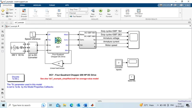
The Four-Quadrant Chopper DC drive DC7 block model, 3 Phase Voltage source and AC to DC Converter contains Rectifier bridge and Braking Chopper is added to Four-Quadrant Chopper DC drive DC7 block. The armature Voltage is provided by IGBT converter controlled by two PI regulators. The first regulator is Speed regulator and followed by Current regulator.
Working principle:
The four-quadrant chopper is a chopper which can operate in all the four quadrants. The power can flow either from source to load or load to source in this chopper. In the first quadrant chopper acts as a Step-down chopper whereas in the second quadrant it behaves as a Step-up chopper. This type of chopper is also known as a Class-E or Type-E chopper.
A dc‐to‐dc converter, also known as dc chopper, to obtain a variable dc voltage from a constant dc voltage source. They are also used as dc voltage regulators. Choppers are of two types: (1) Step‐down choppers, and (2) Step‐up choppers.
step‐down choppers, the output voltage will be less than the input voltage.
step‐up choppers, the output voltage will be more than the input voltage.
Circuit of four Quadrant chopper:
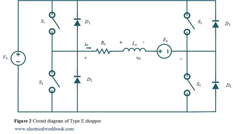
The four quadrant chopper consists of four Semiconductor switches (S1,S2,S3,S4) and diodes (D1,D2,D3,D4) which are connected in parallel to switches.
Operation:
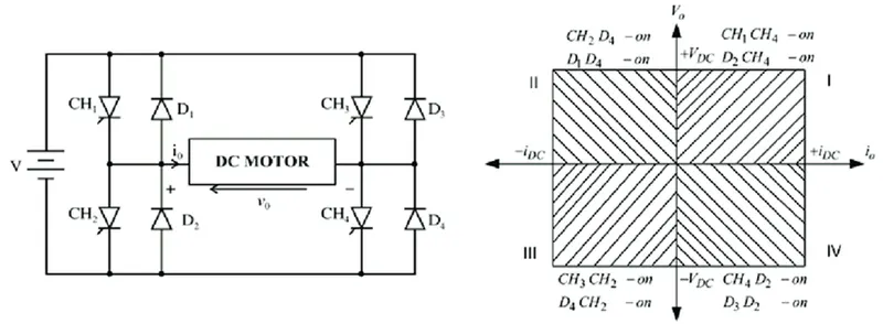
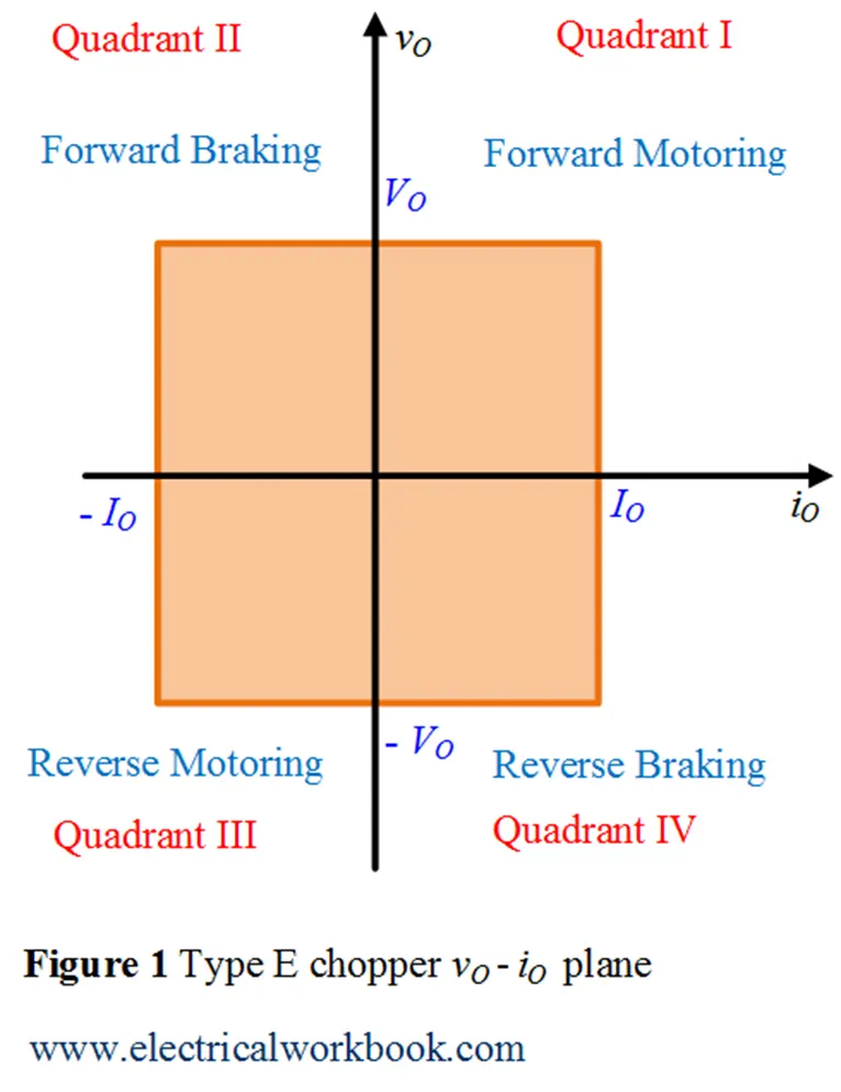
First Quadrant: From the above diagram, in first quadrant thyristors CH1 and CH4 are On, then the Dc motor is directly connected in between the CH1 and CH4 Thyristors. Current Io is flows in forward direction (+V>CH1>DC MOTOR>CH4>-V). when the CH1 and Ch4 are OFF, the current free-wheels through the CH4 and D2. In this motor rotates in forward direction. These Quadrant is called forward motoring.
Second Quadrant: CH2 is operated while keeping the CH1, CH3 & CH4 OFF. When CH2 is ON, the DC source in the load drives current through CH2, D4, E and L. Inductor L stores energy during the on period of CH2. When CH2 is OFF, current is feed back to the source to D1,D4. At this point E+Ldi/dt supply more voltage than the source voltage. Load voltage Vo is positive and current Io is negative. This is second Quadrant operation. here load is transferring power to the source. It is termed as step-up chopper.
third Quadrant: To obtain the third quadrant operation, both the load voltage and load current should be negative. CH3 is operated while keeping the CH1, CH3 & CH4 OFF. When CH2 is ON, the DC source is connected to load voltage. But the polarity of load voltage Vo is opposite. Hence Vo is negative and current direction is also opposite. It is also negative. This is the third Quadrant operation. CH3 is OFF, the current free flows through the CH2 and D4. Here both Vo and Io are negative.
Fourth Quadrant: To obtain the fourth quadrant operation, CH4 is operated while keeping the CH1, CH2 & CH3 OFF. When CH4 is ON, the positive current flows through CH4,D2,L,and E. Inductance L stores the energy during the time CH4 is ON, When CH4 is made OFF, the current is fed back to the source through diodes D2, D3. Here load voltage is negative, but the load current is always positive. This leads to chopper operation in the fourth quadrant. Here, power is fed back to the source from the load and the chopper acts as a step-up chopper.
Output:
Speed refrences:
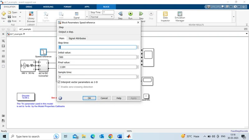
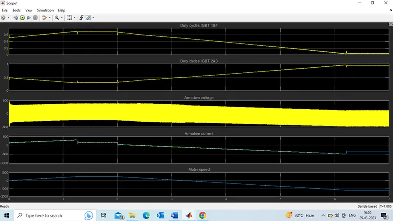
From the output, Motor speed follows the speed references (Initial value is 500 rpm and final value is -1184 rpm). Here motor is connected to linear load, speed of the motor is directly proportional to load Torque. Armature current follows the current reference to control the load torque and maintain desired speed.
At 0 Sec, motor speed at zero and goes to reach the initial speed. At 1.3 sec motor speed reaches to its initial speed 500 rpm ( steady state value). After 2.2 sec speed reverse occurs and decrease to final value(-1184 rpm @6.3 sec). At 3.0 sec speed crosses the zero speed.
In same time, Armature current matches its current reference values, at 1.3 sec it reaches to steady sate value (300 amps) and at 2.2 sec it starts decreasing and reaches negative final value at 6.3 sec.
The positive values refers the motor acceleration time and reaches its maximum values. When negative value refers the motor deceleration (up to zero speed) and braking time (negative torque)
Comparison of Four Quadrant chopper model with H-Bridge model:
1. In four quadrant choppers, motor can operate in all the four quadrants, Forword motoring, Forword braking, reverse motoring, reverse braking. Whereas in H-bridge motor can operate in two quadrants, Forword and reverse.
- four Quadrant chopper are mainly applicable in switching circuits, power circuits, signal applications. H-bridge circuit is used in robotic and where motor is operated in only two Quadrants.
- the four Quadrant choppers are applicable for regenerative braking, H-bridge is not applicable for Re-generative braking.
4. the four-quadrant chopper have four semiconductor switches with four diodes, whereas in H-bridge have four semiconductor switches and four diodes.
- the Four Quadrant chopper circuit little complex to understand compared to H-bridge.
- In four quadrant chopper circuit consists two PI regulators (speed regulator and current regulator) to obtain desired speed and control on Armature current and stabilize the system. H-bridge circuit not used the PI regulators.
- Four quadrant chopper have high efficiency and performance than H-bridge model.
Task-2:
TWO-Quadrant chopper modelling using Simulink.
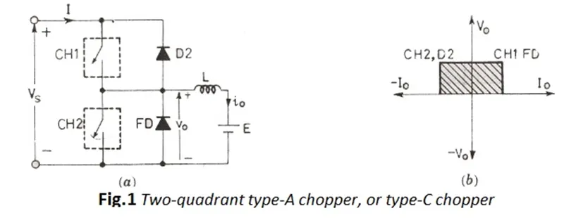
In this type of Chopper, the average voltage will be always positive but the average load current might be positive or negative. The two Switches CH1 and CH2 should not be turned on simultaneously as the combined action may cause a short circuit in supply lines. For regenerative braking and motoring this type of chopper configuration is used.
We will always get a positive output voltage as the freewheeling diode FD is present across the load. When the chopper CH1 is on the current flows from source to load. The inductor stores energy. When Ch1 turn OFF the freewheeling diode starts conducting and the output voltage will be equal to Source voltage. The direction of the load current will be reversed. The current will be flowing towards the source. The load current will be negative when the CH2 is on. The current completes its path through diode D2.
Now we going to model the two-quadrant chopper using Simulink, which is same as circuit diagram.
Simulink Model:
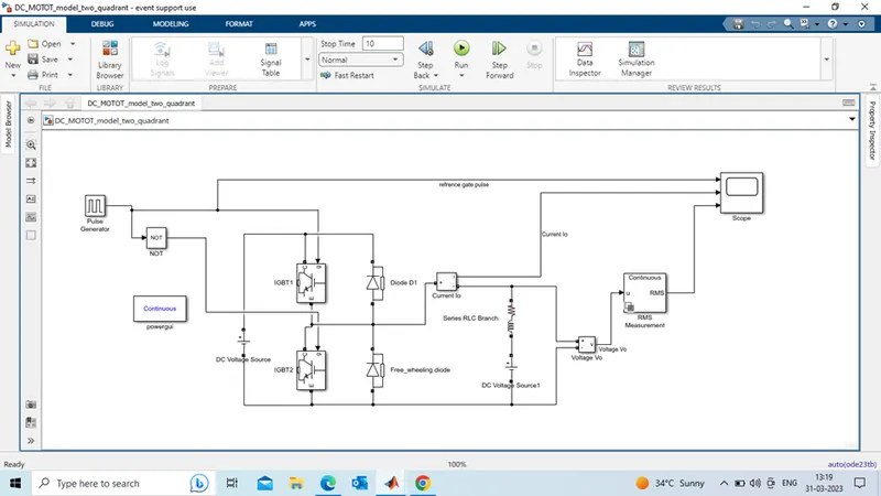
In model, we have used following blocks,
- Pulse generator
- Logical operator (NOT)
- IGBT
- DC voltage source
- Diode
- Current measurement
- Voltage measurement
- RMS measurement
- Series RLC branch for inductor and resistor
- Scope
Pulse generator, DC voltage sources parameters setting:
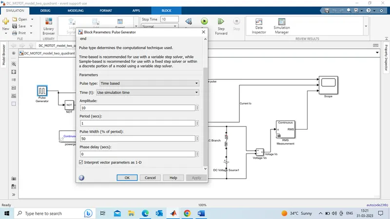
Considering 50% pulse width, therefore gate signal Switching on to flow 50% of voltage through the IGBT at every 1.0 sec.
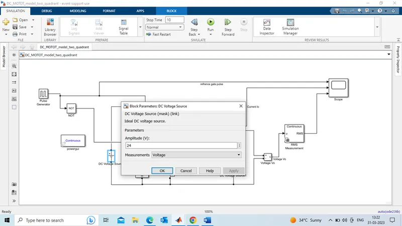
Consider Supply Source voltage 24V.
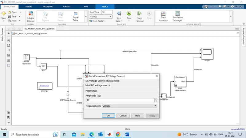
Consider, Back EMF voltage 12V.
Output: IGBT
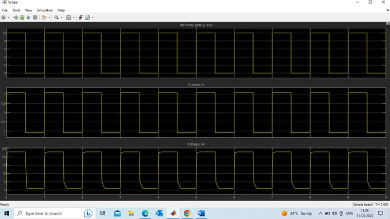
From the above results, the current flows in both forward and reverse direction (positive and negative). And voltage is always positive, not crossing zero value. Which is TWO-Quadrant operation (forward motoring and Forward braking Quadrants).
Here the current reaches maximum of +1.1 amps in forward direction and it reaches to maximum-1.1 Amps in reverse direction. Current wave form shows exact of reference signals. Initially current conducts in forward direction from (0 to 0.5 sec) through IGBT1 and Free-wheeling diode, after IGBT1 off, Due to the inductor effect, the output voltage will equal to the source voltage. Then current conducts in reverse direction (0.5 to 1.0 sec). Through IGBT2 and Diode D1. Voltage will always be positive, Source polarity not changed in both Quadrants.
TASK-3:
Brushless DC motor:
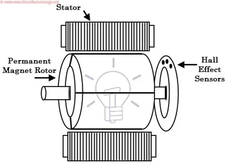
Brushless DC electric motors also known as electronically commutated motors (ECMs, EC motors).
Construction:
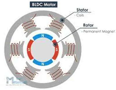
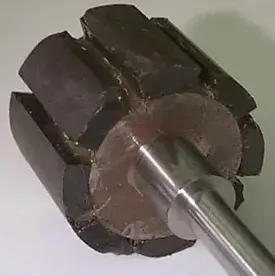
In this motor, the permanent magnets attach to the rotor. The number of poles in the rotor can vary from 2 to 8 pole pairs with alternate south and north poles depending on the application requirement.
The current-carrying conductors or Armature winding are located on the stator. They use electrical commutation to convert electrical energy into mechanical energy.
The main design difference between a brushed and brushless motors is the replacement of mechanical commutator with an electric switch circuit. A BLDC Motor is a type of synchronous motor in the sense that the magnetic field generated by the stator and the rotor revolve at the same frequency.
Brushless motor does not have any current carrying Commutator. The field inside a brushless motor is switched through an amplifier which is triggered by the commutating device like an optical encoder.
Working Principle of Brushless DC motor:
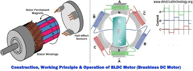
BLDC motor works on the principle similar to that of Brushed DC motor. The Lorentz force law which states that whenever a current carrying conductor placed in a magnetic field it experiences a force. As a consequence of reaction force, the magnet will experience an equal and opposite force. In the BLDC motor, the current carrying conductor is stationary and the permanent magnet is moving.
When the stator coils get a supply from source, it becomes electromagnet and starts producing the uniform field in the air gap. Though the source of supply is DC, switching makes to generate an AC voltage waveform with trapezoidal shape. Due to the force of interaction between electromagnet stator and permanent magnet rotor, the rotor continues to rotate.
With the switching of windings as High and Low signals, corresponding winding energized as North and South poles. The permanent magnet rotor with North and South poles aligns with stator poles which causes the motor to rotate.
HALL SENSOR: Hall sensor provides the information to synchronize stator armature excitation with rotor position. Since the commutation of BLDC motor is controlled electronically, the stator windings should be energized in sequence in order to rotate the motor. Before energizing a particular stator winding, acknowledgment of rotor position is necessary. So the Hall Effect sensor embedded in stator senses the rotor position. Most BLDC motors incorporate three Hall sensors which are embedded into the stator. Each sensor generates Low and High signals whenever the rotor poles pass near to it. The exact commutation sequence to the stator winding can be determined based on the combination of these three sensor’s responses.
Based on this signal from sensor, the controller decides particular coils to energize. Hall-effect sensors generate Low- and High-level signals whenever rotor poles pass near to it. These signals determine the position of the shaft.
Advantages of BLDC motor:
1.Less Maintenance. Due to no mechanical commutator.
2.High efficiency due to the use of permanent magnet rotor.
3.High speed of operation even in loaded and unloaded conditions due to the absence of brushes that limits the speed.
4.Smaller motor geometry and lighter in weight than both brushed type DC and induction AC motors.
5.less space required.
6.Speed control is easy.
7.Less electromagnetic interference.
8.Smooth rotation (low noise) due to absence of brushes.
9.Position of rotor can be access by hall effect sensors.
Dis-advantages:
- BLDC motor is costly, due Permanent magnets
- Additional controller required, means more expensive
- It needs additional sensors.
- It can cater the small load, due to zero initial torque.
Applications:
- Electric vehicles, Hybrid vehicles.
- Roberts, belt driven system.
- Compressors and dryers.
- Fans, pumps and blowers.