Week-7 Challenge: DC Motor Control
1.Speed control of a DC motor using BJT H-bridge
At first, to run the speed control model of a DC motor using BJT H-bridge in matlab, the command - (power_Hbridge) is run in the command window of MATLAB.
We get a simulink window of the model as shown below
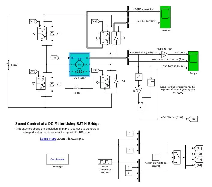
From the above image it is seen that the model consists a motor(5HP 240V 1750rpm field:300V), which is connected to a 240V supply with four bipolar junction transistors(BJT) and diodes, which acts as full bridge rectfiers. The model is know as H-bridge because the connection of the BJT's and diodes are in such a way that switches the polarity of the voltage applied to the motor.
The two basic states of the h-bridge is show below
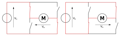
From the above circuits, it shows that voltage can be applied in both the direction when using a H-bridge structure.
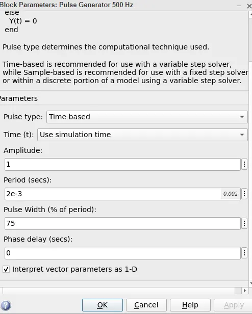
The frequence of the switching is controled by the pulse generator block of the model. The pulse generator consists of inputs such as amplitude, period, pulse width (or) duty cycle and phase delay. The outputs of the pulse generator block are P1, P2, P3 and P4 which are connected to the BJT's. When the pulse width is changed, the results of the pulse generator changes which in turn control the output direction and speed of the motor.
Scopes are attached accordingly to get the graphs of IGBT current, diode current, speed of the motor in (rpm), armature current in (A) and load torque in (N-m). The torque is calculated by using the relation between the torque and speed of a motor.
Simulation of the model with no modifications in the pulse generator block.
The default value of pulse width is 75. The pulse generator block is given below.
Result of simulation.
The scope consisting the speed of the motor, armature current and load torque of the motor is given below.
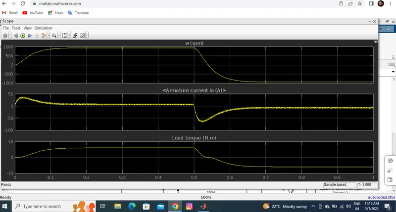
From the result it is seen that the armature current shoots up when the motor is made to change direction at 0.5s of the simulation.
Simulation of the model with change in the pulse generator block.
The default value of pulse width 75 is reduced to 50 and then the model is simulated.
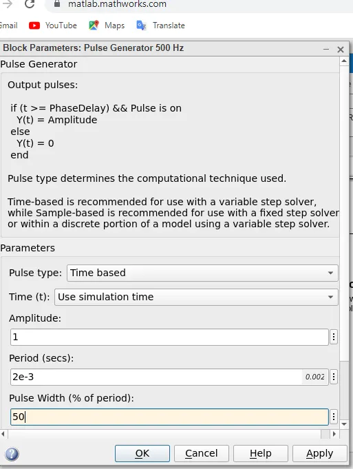
Result of simulation.
The scope consisting the speed of the motor, armature current and load torque of the motor is given below.
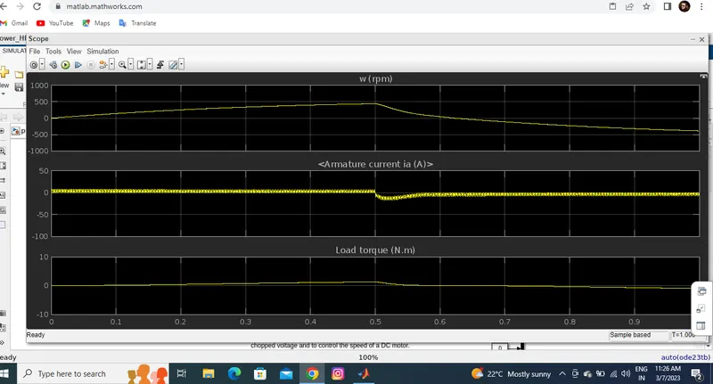
From the result we can see that @ T=0.5 of the simulation the motor changes direction and the current shoot is reduced accordingly. Due to the reduced pulse width, the speed of the motor and the load torque is also reduced.
Simulation of the model with change in the pulse generator block.
The pulse width is again reduced from 50 to 25 percent and then simulated.
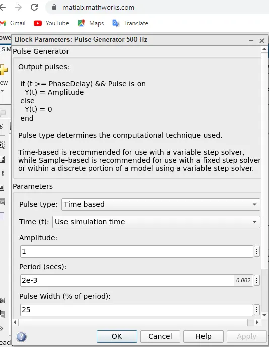
Result of the simulation
The scope consisting the speed of the motor, armature current and load torque of the motor is given below.
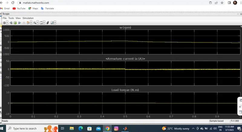
From the result it is see that, the current does not shoot up when the motor changes direction @ T=0.5s of the simulation. The speed of the motor and the load torque in of the motor are low.
Conclusion
From all the simulations it is concluded that, when the duty cycle of the pulse generator block is low then the speed, current and load torque is also low accordingly.
3. Comparing ‘The Four-Quadrant Chopper DC Drive (DC7) block’ with H bridge model:
Block:
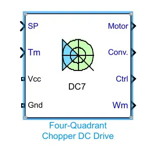
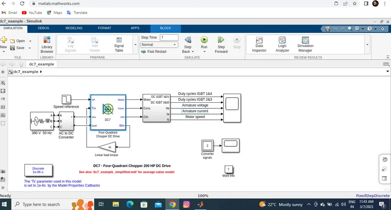
The Dc7-four quadrent chopper 200 HP DC drive model is opened by running the command (dc7_example) using the command window of MATLAB.
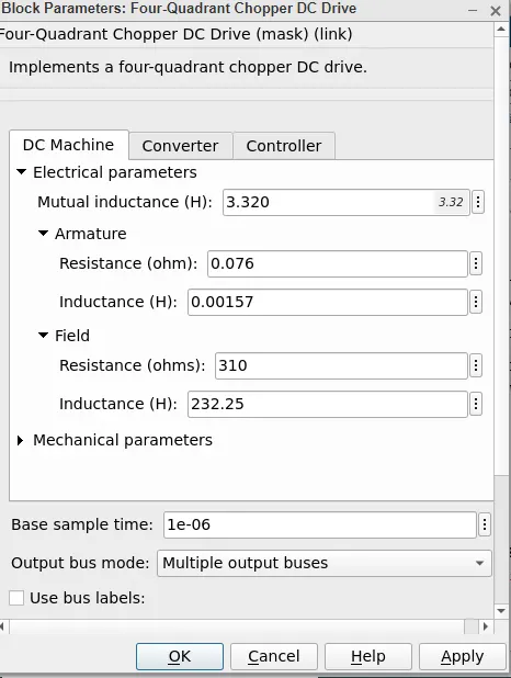
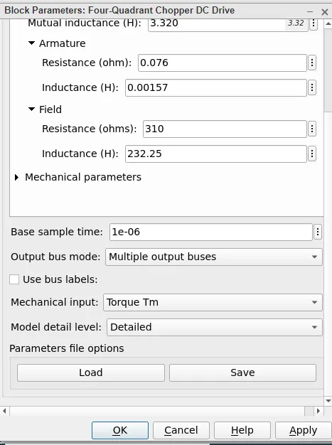
The simulation window of the model is given below.
By simulating the model the results plot from the scope is given below.
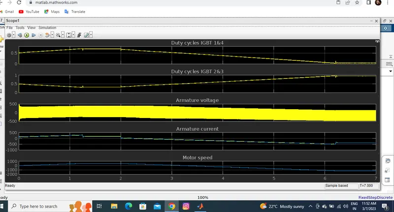
Comparison of The Four-Quadrant Chopper DC Drive (DC7) block with H-bridge
>The simulation is continuous in H-bridge whereas the simulation is discrete using a four quadrent chopper DC drive.
>Since H-bridge uses continuous simulation the simulation time is less when compared to DC7 block.
>Direction of the motor can be changed by changing the polarity in a H-bridge structured circuit and, the direction of the motor can be changed in a four quadrant chopper DC drive by changing the input signal to the DC7 block.
>Use of snubber in H-bridge circuit is not required but it is required for the DC7 block. This is due to the rapid raise in the voltage when a change in the input signal occurs in the DC7 block.
>Speed of the motor can be varied by variying the duty cycle of the motor in H-bridge circuit. In the DC drive with DC7 block speed of the motor can be varied by the input signal or speed reference.
>Regenerative braking can be done in H-bridge circuit but cannot be done in the four quadrant chopper DC drive.
2. Two quadrant Chopper
Class - C chopper is a Two quadrant Chopper. Its functions in the 1st and 2nd quadrants.
In class C chopper, output voltage is always positive and output current can be positive or negative. This type of chopper obtains by connecting class-A and class - B chopper in parallel.
Chopper model:
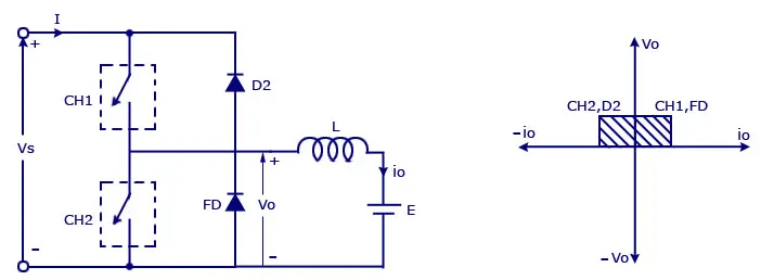
Where,
Vs=DC voltage source.
CH1= Power electronic switch 1.
CH2= Power electronic switch 2.
D2,FD = Free wheeling diodes.
L=Inductor load.
E Back emf from load.
Mode of operation:
- Here either one should be ON at a time,either CH1 or CH2.
- If CH1 is ON the current flows from source +ve to load(here DC motor),passes through L and E to -ve terminal of source.(1st quadrant)
- If CH1 is OFF the, FD diode conducts and complete the circuit (L-E-FD-L) as stored energy in inductor L.The voltage across is also positive voltage,current direction also positive.
- Now If CH2 is ON,Current flow from E(Load current) completes the circuit(L-CH2-E).
- If CH2 gets OFF,the current passes through D2 towards source completes the circuit(E-L-D2-+ve source- -ve source-E).
- In this stage regenerative breaking occurs.(2nd quadrant).
- This cycle continuous again upto stop time.
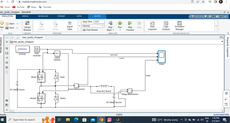
3. BLDC motor.
Primary efficiency is a most importent feature for BLDC motors. Because the rotor is the sole bearer of the magnets and it doesn't require any power. i.e. no connections, no commutator and no brushes. In place of these, the motor employs control circuitry. To detect where the rotor is at certain times, BLDC motors employ along with controllers, rotary encoders or a Hall sensor.
Construction
In this motor, the permanent magnets attach to the rotor. The current-carrying conductors are located on the stator. They use electrical commutation to convert electrical energy into mechanical energy.
The main design difference between a brushed and brushless motors is the replacement of mechanical commutator with an electric switch circuit. A BLDC Motor is a type of synchronous motor in the sense that the magnetic field generated by the stator and the rotor revolve at the same frequency.
Operation
BLDC motor works on the principle similar to that of a Brushed DC motor. The Lorentz force law which states that whenever a current carrying conductor placed in a magnetic field it experiences a force. As a consequence of reaction force, the magnet will experience an equal and opposite force. In the BLDC motor, the current carrying conductor is stationary and the permanent magnet is moving.When the stator coils get a supply from source, it becomes electromagnet and starts producing the uniform field in the air gap. Though the source of supply is DC, switching makes to generate an AC voltage waveform with trapezoidal shape. Due to the force of interaction between electromagnet stator and permanent magnet rotor, the rotor continues to rotate. With the switching of windings as High and Low signals, corresponding winding energized as North and South poles. The permanent magnet rotor with North and South poles align with stator poles which causes the motor to rotate.