Week-7 Challenge: DC Motor Control
1) Speed control of a DC motor using BJT H-bridge:
The Following simulation shows an H-bridge used to generate a chopped voltage and to control the speed of a DC motor.
DC motor model: 5 HP 24V 1750 rpm.
Load Type: fan load (where Load torque is proportional to square of speed).
Armature voltage : 0 to 240 V when the duty cycle is varied from 0 to 100%.
POwer Device: BJT with antiparallel diode (modeled as IGBT).
Working:
Two transistors are switched simultaneously: Q1 and Q4 or Q2 and Q3.
- When Q1 and Q4 are fired, a positive voltage is applied to the motor and diodes D2-D3 operate as free-wheeling diodes
- When Q1 and Q4 are switched off. When Q2 and Q3 are fired, a negative voltage is applied to the motor and diodes D1-D4 operate as free-wheeling diodes when Q2 and Q3 are switched off.
Simulation Results are discussed below:
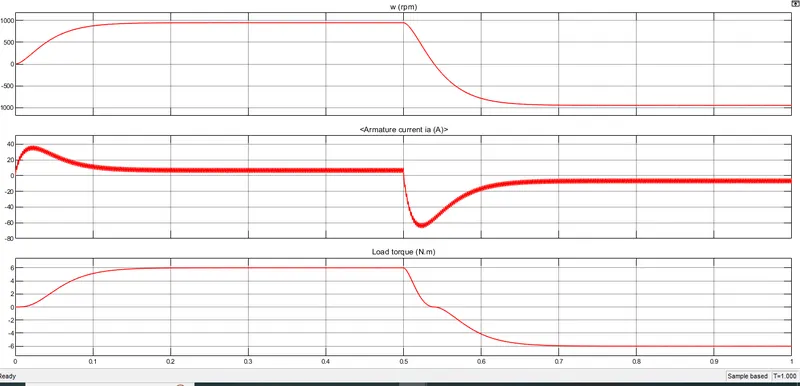
From the results, The model is simulated at 75% of duty cycle. the motor RPM has increased to 950RPM(Maximum).
Armature current shoots upto 40A at transient in forward direction and reduces to 10A.
when reverse, Armature current shoots upto 60A at transient and reduces to 10A.
Load Torque: 6Nm.
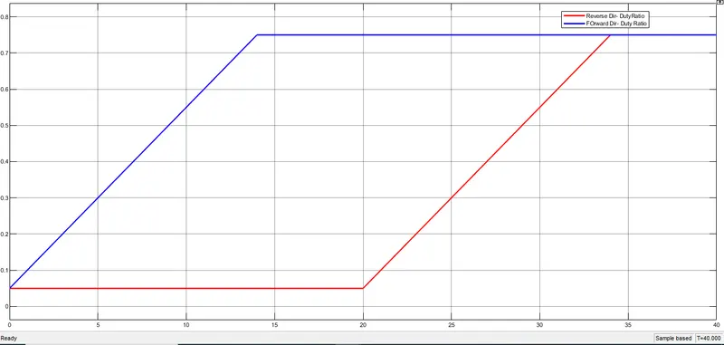
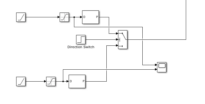
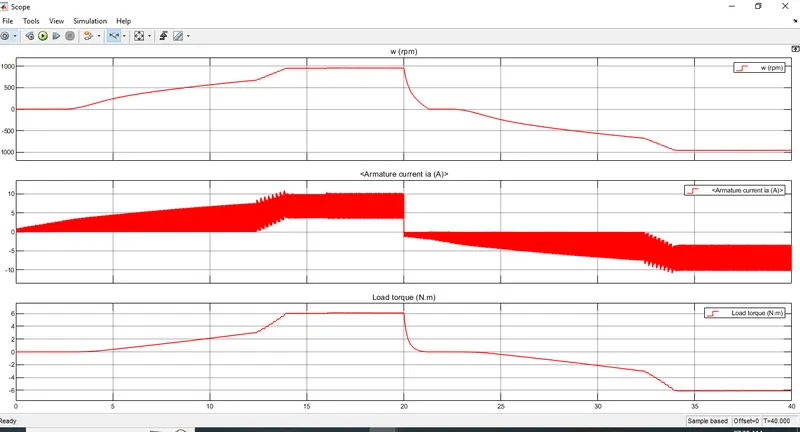
To reduce the armature current shoots up, by increasing duty cycle gradually 0 - 75%.
Comparison:
|
Four-Quadrant Chopper DC Drive |
H-bridge model |
|
To change the motor direction the polarity is changed |
To change the motor direction the current signal has to be interrupted. |
|
It has broader torque and power output ranges |
It uses single pulse generator which gives narrow torque and power output range. |
|
the current has chopped values. |
the current has continuous values. |
|
Regenerative braking is possible |
Regenerative braking is not possible |
2) Two Quadrant Chopper :
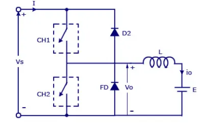
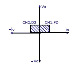
Two Quadrant Chopper schematic is shown. The chopper permits a change in the polarity of input voltage by keeping the direction of current constant. CH1 and CH2 are working as electronic switch and D1 and D2 are the feedback diodes.
For first quadrant operation, CH1 is ON or FD conducts. For second quadrant operation, CH2 is ON or D2 conducts.
• When CH1 is ON, the load current is positive.The output voltage is equal to ‘V’ & the load receives power from the source.
• When CH1 is turned OFF, energy stored in inductance L forces current to flow
through the diode D2 and the output voltage is zero. Current continues to flow in positive direction.
• When CH2 is triggered, the voltage E forces current to flow in opposite direction
through L and CH2 . The output voltage is zero.
• On turning OFF CH2 , the energy stored in the inductance drives current through
diode D1 and the supply, Output voltage is V, the input current becomes negative and power flows from load to
source.
• Average output voltage is positive
• Average output current can take both positive and negative values.
• Choppers CH1 & CH2 should not be turned ON simultaneously as it would result in
short circuiting the supply.
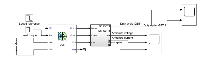
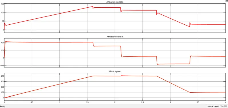
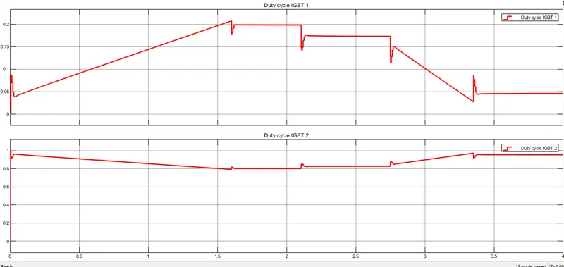
Matlab simulation of Two Quadrant chopper is simulated and shown below:
3) Operation of BLDC motor:
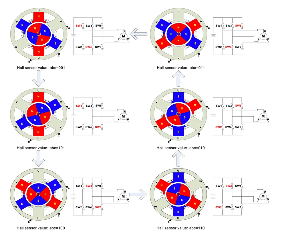
BLDC motor works on the principle similar to that of a Brushed DC Motor. The Lorentz force law which states that whenever a current carrying conductor placed in a magnetic field it experiences a force. As a consequence of reaction force, the magnet will experience an equal and opposite force. In the BLDC motor, the current carrying conductor is stationary and the permanent magnet is moving.
When the stator coils get a supply from source, it becomes electromagnet and starts producing the uniform field in the air gap. Though the source of supply is DC, switching makes to generate an AC voltage waveform with trapezoidal shape. Due to the force of interaction between electromagnet stator and permanent magnet rotor, the rotor continues to rotate.
With the switching of windings as High and Low signals, corresponding winding energized as North and South poles. The permanent magnet rotor with North and South poles align with stator poles which causes the motor to rotate.
Advantages of Brushless DC motor:
- Less overall maintenance due to absence of brushes
- Reduced size with far superior thermal characteristics
- Higher speed range and lower electric noise generation.
- It has no mechanical commutator and associated problems
- Less electromagnetic interference
- Low noise due to absence of brushes
Limitations of Brushless DC motor:
- These motors are costly
- Electronic controller required control this motor is expensive
- Requires complex drive circuitry
Applications of Brushless DC motor :
- Computer hard drives and DVD/CD players
- Electric vehicles, hybrid vehicles, and electric bicycles
- Fans, pumps and blowers.