Project 2
Design of Interleaved DC-DC converter:
Given:
Input voltage: 45 – 60 V
Output voltage: 3 V
Output current: 100A
With reference to the Design Constrain, I had choosen Flyback converter.
Calculate Unknowns:
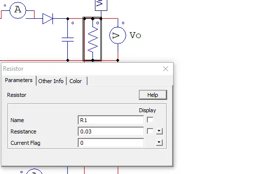
Load resistor: R = Vout/Iout = 3/100 = 0.03 ohms
Let Take Switching Frequency Fsw = 50kHz
Output Power = 3*100 = 300Watts
Duty ratio:
Let us take turns Ratio be 30:3
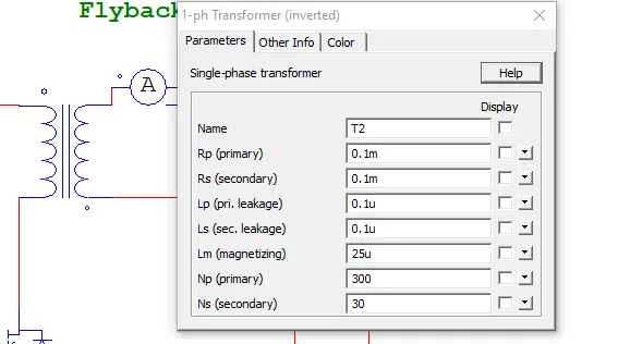
N1 = 300; N2 = 30
The output equation of flyback converter is
Vout = Vin *D*N2/(1-D)*N1
by solving we get
D = 0.33 at Vin = 60V
D = 0.4 at Vin = 45V
Calculation of Inductor Current:
The inductor current is calculated in worst case of input Vin = 45V.
IL = P/(Vin*D)
By solving we get
Il = 300/(45*0.4) = 16.667A
To operate the converter in CCm mode:
Lmin > 10.8uH
Let take magnetising Inductance be 25uH.
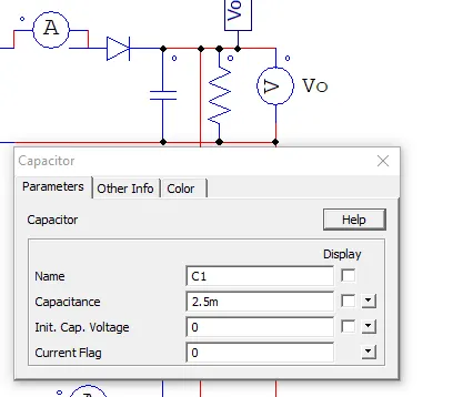
Output Capacitance:
Let choose 5% of output votage ripple
DeltaVo = 5/100*3 = 0.15V
Cout = Vout*D/(R*Fsw*DeltaVo)
By Solving we get Cout = 5.3mF
From the Design Constraint, we need to design the converter in interleaved to make efficiency greater than 90%.
For the Interleaving DC-DC Converter, The same values be repeating the with two identical converter are connected in parallel, so that PWM are given 180 degree Phase shift. The capacitance values of the each converter is calculated by Cout/2.
Schematic Of Designed Converter:
The schematic of proposed interleaved converter is shown in figure 1 and 2.
The DC-DC converter is simulated in PowerSim software and its schematic is shown both Open loop and closed loop. the results are shown in closed loop.
Figure 1: Open loop Interleaved Flyback Converter.
In Open loop converter, PWM signals are provided directly to the Switch.
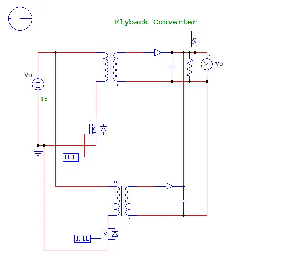
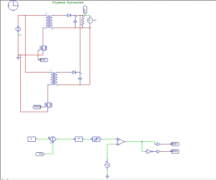
Figure 2: Closed loop Interleaved Flyback Converter.
Closed loop converter is designed by taking Output voltage as feedback such that Duty ratio will be varied with respect to feedback.
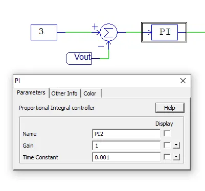
The output voltage is taken as a feedback and is compared with reference value 3V. The Error signal generated is feed to PI controller. the output from the PI controller is feed to comparator. the sawtooth switching signal of 50kHz is compared with PI controller Output and output of comparator is feed to PWM will sent to MOSFET Switch.
For the other converter, the PWM signal from the comparator is fed to NOT gate (to make 180 degree out of phase) and fed to aother MOSFET Switch.
Results and Discussion:
The DC-DC converter is simulated in POWERSIM and results are shown below.
1) Output Voltage and Output Current:
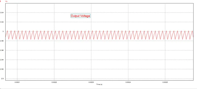
The output voltage reaches the steady state is around 1ms. the transient peak voltage is around 5V peak.
The output voltage obtained is around 3V and Voltage ripple of 0.1V(Peak to peak) which is less than calculated.
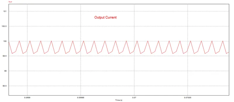
The average output current is around approx. 100A.
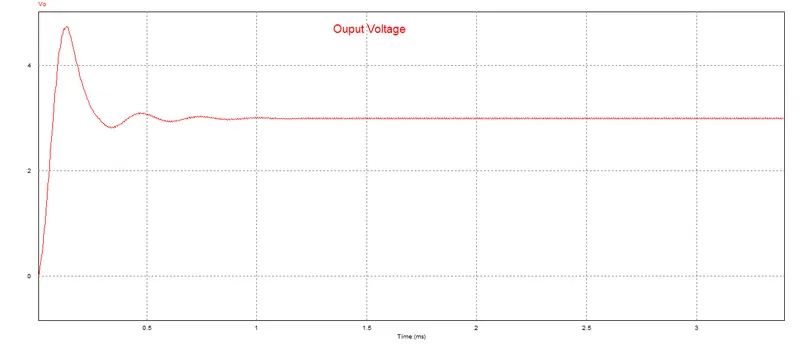
Output Voltage and Output Current are shown in Zoom in Version.
2) Inductor Current and SWITCH Current
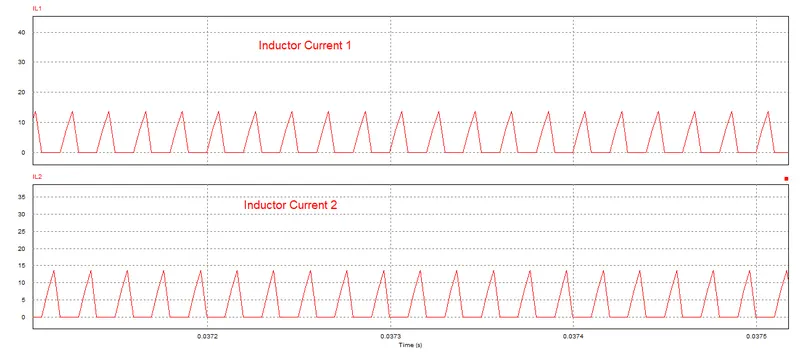
As we see, when MOSFET is ON, Inductor charges and Discharges when MOSFET is OFF condition. The stored Energy during turn ON time will be transfered to secondary side during turn OFF condition.
the peak inductor current is around 17A which is same as MOSFET current. the inductor current is got zero for some time. this indicates that full stored energy will be transfered to output.
PWM signals are provided in 180 degree out of phase. so that the Inductor current in converter 2 will high when converter 1 will be in turn off condition.
3) PWM Signal:
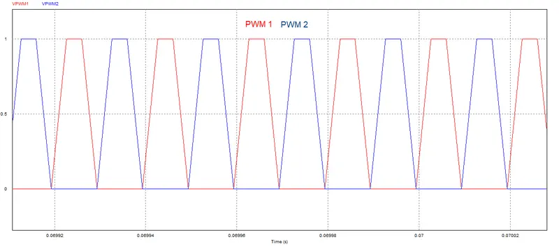
The PWM Signals are shown below. Its states that PWM 1 is high durning PWM 2 is low and vice versa.
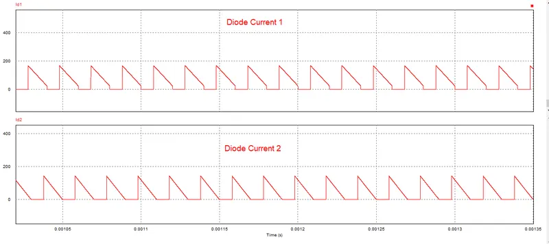
4) Diode Current:
when Diode turn ON, Voltage across the Diode will be equal to Forward Volatge drop (0.8V). The DIODE current starts to conduct when MOSFET turns off to 180A when Switch turns ON. after turns ON the current gradually decreases to approx. 20A.
Diode current in converter 1 and converter 2 are in out of phase.
5) Efficiency
the efficiency of the converter will be calculated by following formula:
η = Power output/ Power input.
Power Output:
Pout = Vout *Iout = 2.98*99.9 = 298Watts
Power Input:
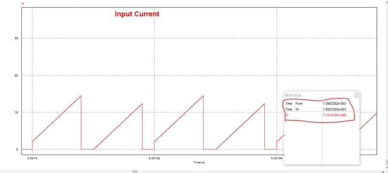
Pin = Vin *Iin = 45*7.14 = 321Watts
η = 298/321 = 93%