Project - Speed Control of a Direct Current (DC) motor
Design a PID controller to regulate the speed of the DC Motor:
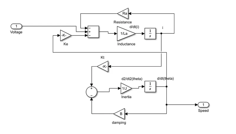
The mathematical block diagram of DC Motor is follows:
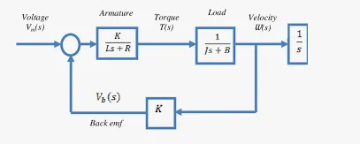
The above block diagram is implemented in simulink as follows:
The Armature current Ia can be calculated by integrating the following equation:
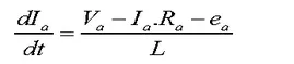
The mechanical torque can be calculated as follows:
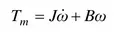
Tm = Kt*Ia
The speed of the DC motor can be calculated as follows:

Let State variable as Ia(Armature current) and Speed (Wm = 𝑑𝛳(𝑡)/𝑑𝑡)
The state space equation are derived as follows:
In the above Equation, Kf =B; Km =Kt(Torque Constant);
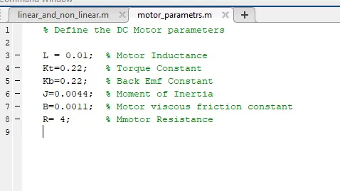
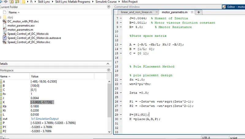
Let us take the Motor parametrs as follows:
L = 0.01 H,
Kt=0.22 N-m/A,
Kb=0.22 V-sec/rad,
J=0.0044 kg-m2,
B=0.0011 N-m-sec/rad,
𝑅= 4 Ω.
Pole Placement Method:
Let us take Natural frequency as Fn = 1.0Hz
W=2*pi*Fn = 6.28 rad/sec
Zeta is consider as under damped system so Zeta = 0.5;
Poles can be calculated as below equations:
P1 = -Zeta*wn +wn*sqrt(Zeta^2-1);
P2 = -Zeta*wn -wn*sqrt(Zeta^2-1);
P=[P1;P2];
The state Feedback matrix can be dervied using the Place command as shown:
K =place(A,B,P);
MATLAB SIMULATION:
1) Define Motor Parameters:
2) Design Using the Parallel PID COntroller:
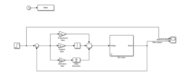
The followings steps are implemented to tune the DC motor for our target condition:
Step 1:
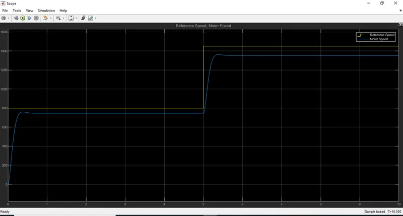
Kp=10; Ki=0; Kd=0;
With help of proportional gain, achieved rise time is around less than 0.3Sec.
Step 2: Increasing Ki to decrease the steady state error:
Kp=10; and ki=5, Kd=0.5;
The response looks like very smart.
Settling time is around 0.8sec;
Overshoot is verty little and Zero steady state error.
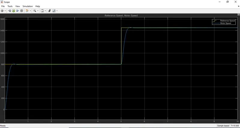
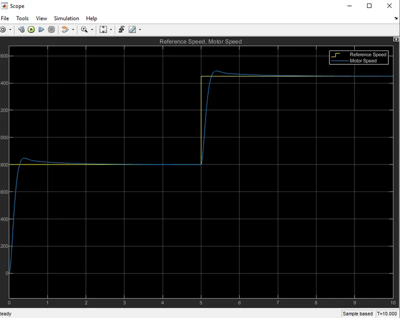
Kp=10; and ki=10, Kd=0.5;
Further increase of Ki, Speed Response overshoot and undershoot.
Settling time is around 3sec;
Steady state error becomes zero at around 3.5 to 4 sec.
With Kp=10; ki=10; kd=5;, The response becomes overshoot and undershoot decreased rise time and takes more settling time more than 5 sec.
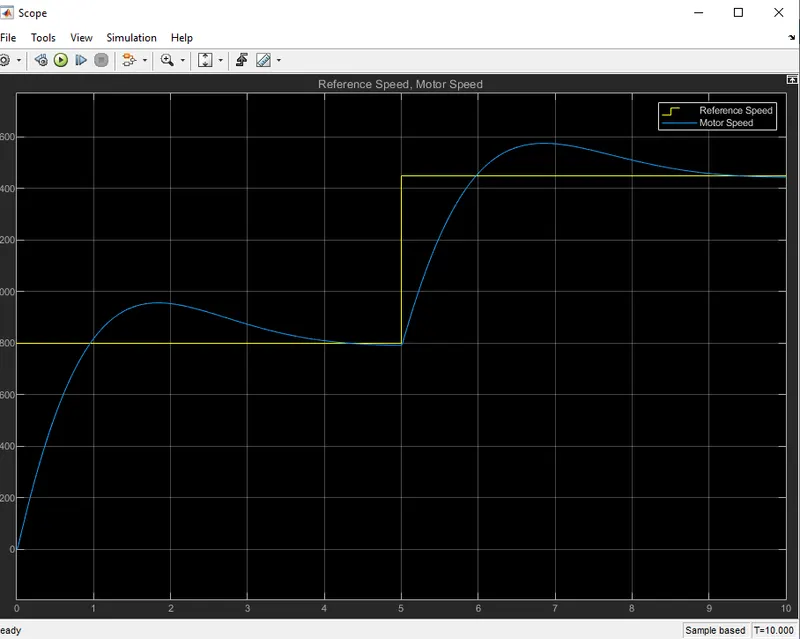
Remarks:
With Kp=10,Ki=5,Kd=0.5, the output speed response of DC motor will approches the target design conditions.
3) Using Pole Placement Design.
The simulink model for Pole placement design as shown:
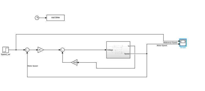
The obtained K = [-3.9; -0.172];
The speed reference X1 = Kd*(x1_ref-X1)-Kd*X2;
Waveforms:
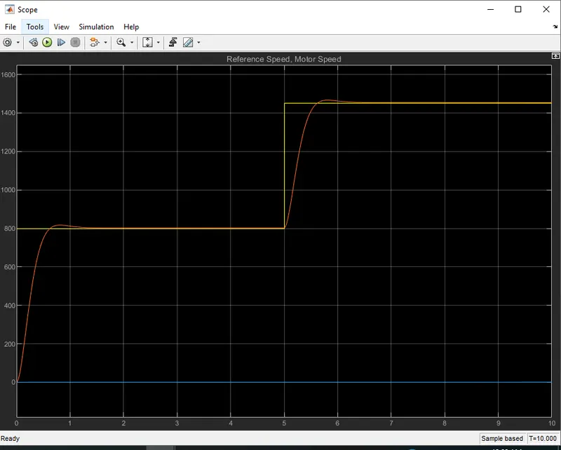
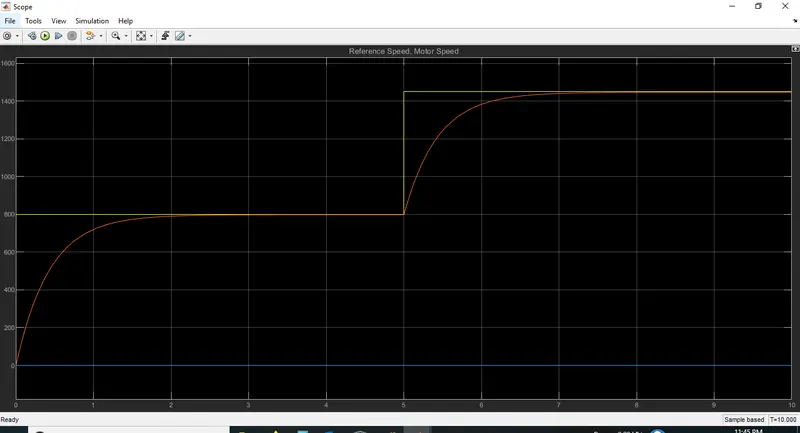
With the above K values, the step response of DC motor are shown below:
Rise time: around 1 sec With No overshoot and zero steady state error.
Let design with Ki with PD Controller to improve the rise time less than 0.5 sec;
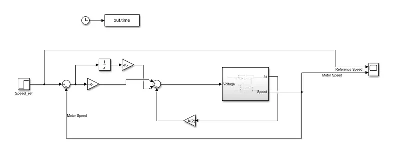
with Ki = 0.1, the response of the DC motor is looking good with little overshoot and ver low rise time around 0.5 sec.