Week-7 Challenge: DC Motor Control
Week-7 Challenge: DC Motor Control
1) A. Explain a MATLAB demo model named ‘Speed control of a DC motor using BJT H-bridge’.
B. Comment on the armature current shoot-up from the scope results.
C. Refer to the help section of ‘The Four-Quadrant Chopper DC Drive (DC7) block’. Compare it with the H-bridge model.
Introduction –
Power BJT -
BJT H Bridge (BiPolar Junction Transistor) it uses 2 n type semiconductors and 2 p type semiconductors connected together forming H-Bridge with motor in between to control the speed and direction of a D.C motor. Diodes are connected in parallel with each transistor to allow passing of current in one direction.
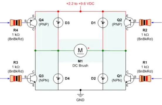
Fig- BJT H Bridge
Switch 1 & 4 are closed when motor needs to operate in forward direction.
Switch 2 & 3 are closed when motor needs to operate in reverse direction. These switches are controlled by signals from power electronic devices setup at particular time duration.
Power BJT H is a three terminal device with very large current and power handling capacity and offer high voltage resistance in OFF state. The construction of power BJT is slightly different than normal logic transistor. It has extra lightly doped region (n-) called as collector drift region in addition to (base contact, emitter contact and collector contact with N, P & N Region depending upon configuration of BJT).
Transistor –
a transistor is a miniature electronic component that can do different jobs. It can work amplifier or a switch.
When it works as an amplifier, it takes in a tiny electric current at one end (an input current) and produces much bigger electric current (an output current) at the other. In other words, it’s a kind of current booster.
Transistors can also work as switches. A tiny electric current flowing through one part of transistor can make much big current flow through another part of it. In other words, the small current switches on the larger one. This is essentially how computer chips work.
Power MOSFET –
It is a type of MOSFET which is specially meant to handle high levels of power. These exhibit high switching speed and can work much better in comparison with other normal MSOFET in the case of low voltage levels. However, its operating principle is similar to that of any other general MOSFET. Powe0r MOSFET are ore generally used in the n – channel enhancement mode or P- channel enhancement mode or n-channel depletion mode in nature.
IJBT –
IJBT (Insulated Gate Bipolar Transistor) constituted of BJT (Bipolar Transistor) and MOS (Insulated Gate Field Effect Transistor) composite full controlled type voltage driven power semiconductor devices with high input impedance MOSFET & GTR’s Low on State voltage drop down. GTR saturation pressure drop, carrier high current density but the drive current is large; MSFET drive power is very small, fast switching speed but large conducting voltage drop, the carrier density is small.
IGBT combines advantage of these two devices, the driving power is small and saturation while voltage drop is low. Very suitable for DC Voltage of 600V& above - Variable flow is AC Motor, Inverter, Switching power supply, lightning circuits, traction drive and other circuits, traction drive and other fields.
IGBT is the youngest one of high voltage switch family. A 15 Volt high impedance voltage source facilitate control current flow through the device which can achieve a lower control power to control the high current.
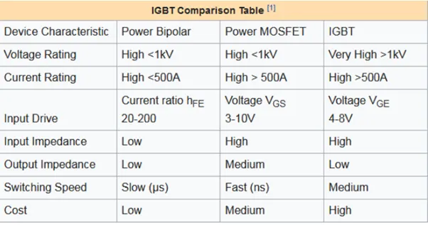
Comparison –
Speed control of D.C. Motor using BJT-H Bridge –
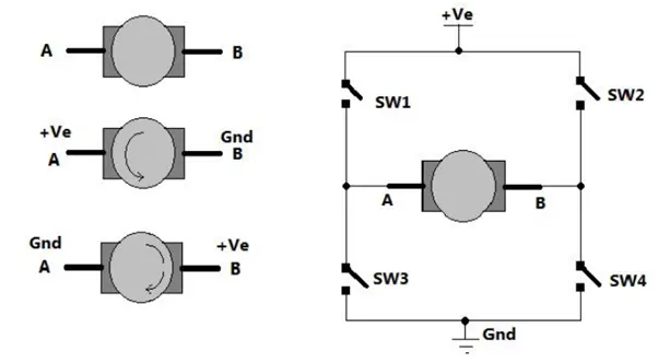
As shown in above figure there are two terminals ‘A’ & ‘B’ of a D.C. motor. Now if we connect terminal A with positive supply and terminal B with negative supply or ground then, the current will flow from motor from A to B and motor will rotate in one direction –say clockwise (CW) or forward direction now as shown in the second figure we have changed supply terminals. Now B is connected with Positive and A is connected to the ground. The current will flow from the motor from B to A and motor will rotate in one direction (Counter clockwise CCW – Reverse Direction).
The arrangement is shown in right side of figure. Four switches are connected in between positive supply and ground and DC motor is connected between two switches as shown. Such circuit arrangement is known as H –bridge because it looks like letter H (H bridge circuits are mostly used in DC motor drivers).
If SW 1 & SW 4 are passed simultaneously then the current will flow from +VE SW 1 - A – B –SW 4 – Gnd. So motor will rotate in one direction. Open (release) SW 1 AND SW 4 to stop the motor. Now if SW 2 & SW 3 to stop motor. Now if SW 2 & SW 3 are pressed so current will flow from +VE SW – B – A –SW 3 – Gnd. So motor will get reverse supply and it will rotate in another direction.
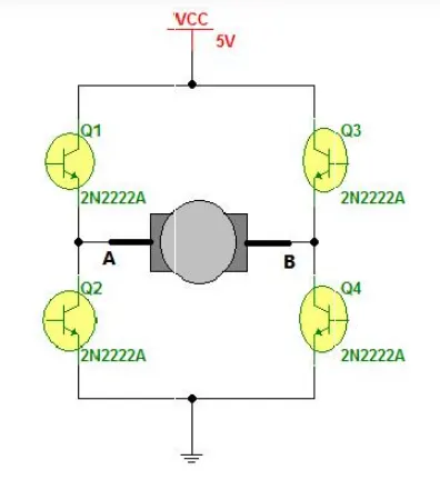
The circuit replace the switches with NPN type transistors. We all know that transistor works as switch, for NPN Transistor if we get +VE input to base it will turn ON and if we give 0 Input it will be turned OFF.
So in this circuit if Q 1 & Q 4 are turned ON simultaneously the motor will rotate forward and if Q2 & Q3 are turned ON then motor will rotate reverse.
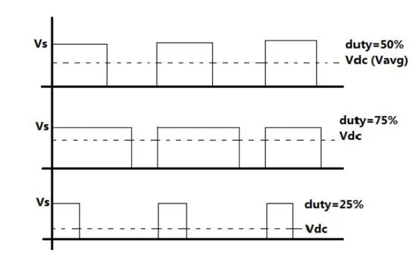
Now let us move to vary the speed of D.C. Motor. The D.C. Motor speed varies as applied input voltage varies, as you increase applied voltage the speed will increase and vice versa. Applying max rated voltage will rotate motor at full speed.
One of the popular methods for generating variable D.C. voltage is pulse width modulation (PWM).
Pulse Width Modulation means varying the width (duty) of pulse. Width means ON time Ton of pulse. The average output voltage (VD.C. / Vavg.) is given by equation-
VD.C. = [Ton / (Toff + Ton )* Vs.
Its directly given by TON. As shown in above figure if duty is 50% the average output voltage Vdc is exactly the half of Vs. if duty is increased to 75% Vdc also increases to 3/4th of the Vs & if duty is decreased to 25% Vdc reduces to 1/4th of Vs. thus are pulse width varies the average output voltage varies. So we have to apply PWM to D.C motor to vary its speed.
Simulation-
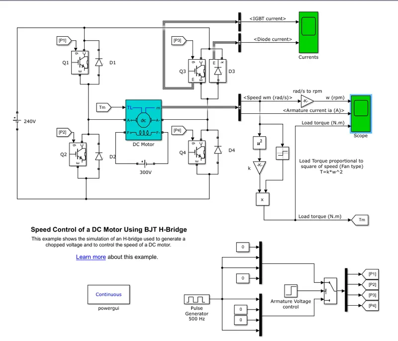
The motor starts in the positive direction with a duty cycle of 75% (Mean D.C voltage of 180V) at t = 0.5 seconds and the armature voltage is suddenly reversed and the motor runs in the negative direction.
Scope shows motor speed, armature, current and load torque and currents shows currents flowing in BJT Q3 and diode D3.
The block has two values of display as output. One is current output for IGBT & the diode current and the other is the scope for the values of the D.C. motor. The values of D.C. motor include –
- Speed (RPM).
- Armature Current (in AMPS).
- Load Torque (N-m).
The output values are as follows-
- IGBT current.
- Diode Current.
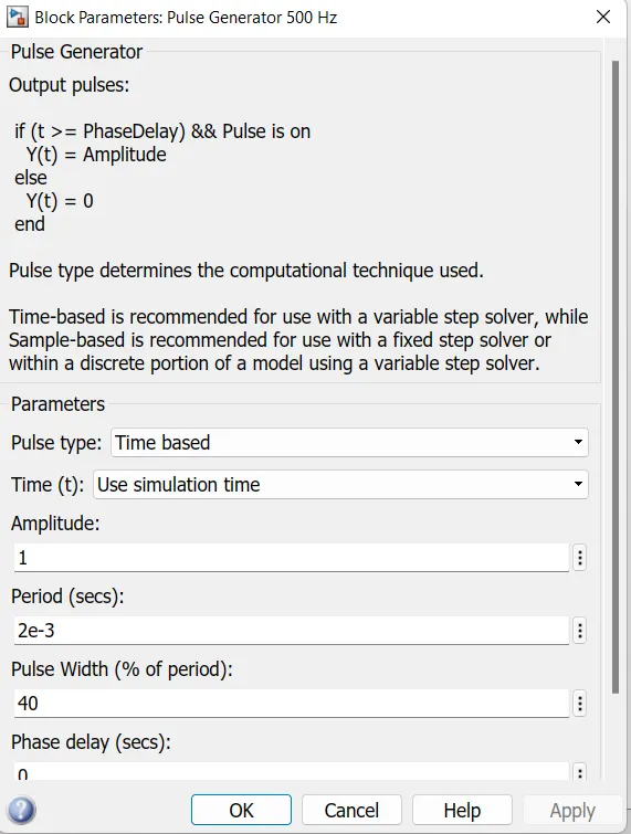
The IGBT block doesn’t simulate the GATE current controlling BJT / IGBT. The switch is controlled by the Simulink signal (1 / 0). The D.C. motor uses the present model (5 HP, 24V, 1750 RPM). It simulates the fan type load (where load torque is proportional to square of speed). The armature mean voltage can be varied from 0 to 240 Volts when the duty cycle (Specified the Pulse – Generator Block) is varied from 0 to 100%.
The H – bridge consist of four BJT / Diode pairs (BJT simulated by IGBT models). Two transistors are switched simultaneously – Q1 & Q4 or Q2 & Q3. When Q1 & Q4 are fired, a positive voltage is applied to the motor and diodes D2 & D3 operate as freewheeling diodes when Q1 & Q4 are switched OFF. When Q2 & Q3 are fired, a negative voltage is applied to the diodes and to the motor and diodes D1 – D4 operate as freewheeling diodes when Q2 & Q3 are switched OFF.
The above Simulink model is run using default conditions we obtain the following input –
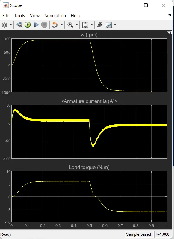
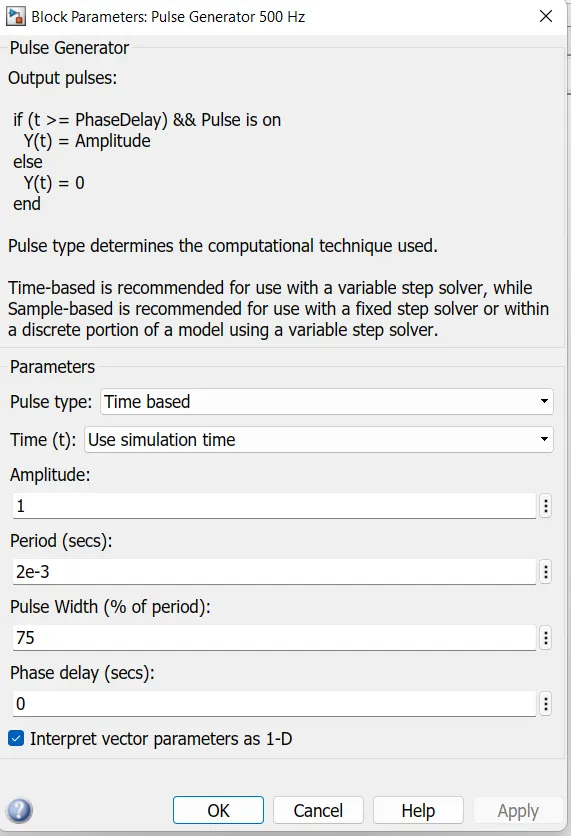
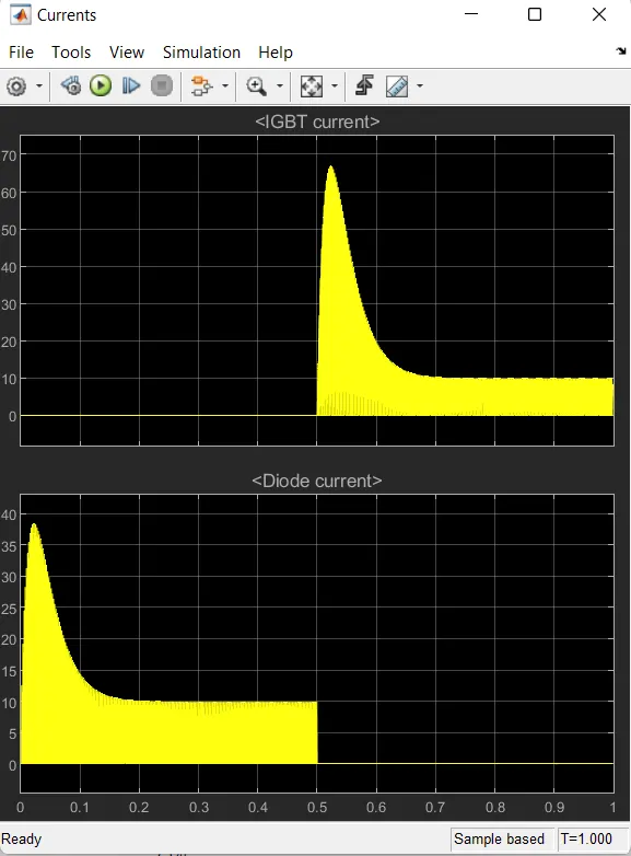
As we can see armature current is changing significantly so in order to control the variation of armature current, we have changed the duty cycle of the battery and observed the variation in armature current, pulse width reduces to 50%.
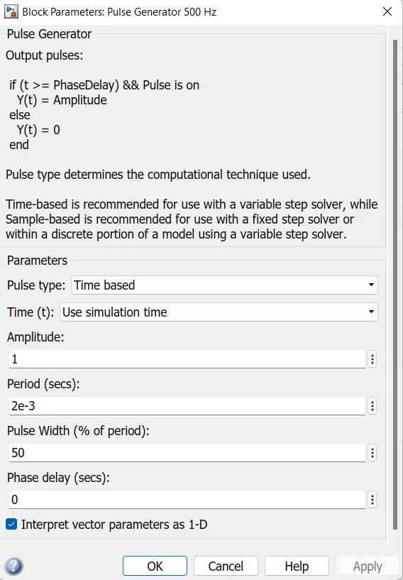
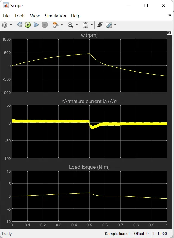
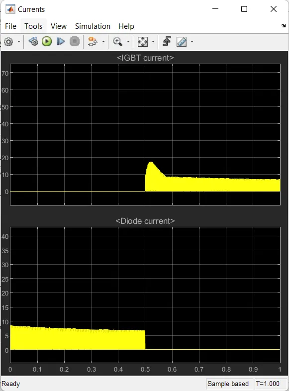
As we can see armature current is changing significantly so in order to control the variation of armature current, we have changed the duty cycle of the battery and observed the variation in armature current, pulse width reduces to 40%.
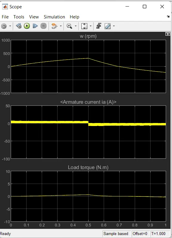
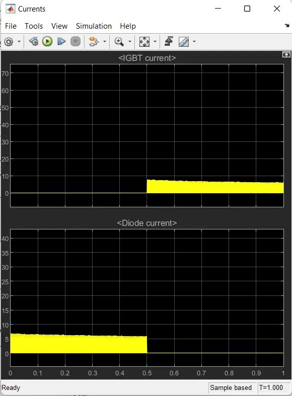
Armature current drops by reducing the duty cycle.
Reverse Modelling –
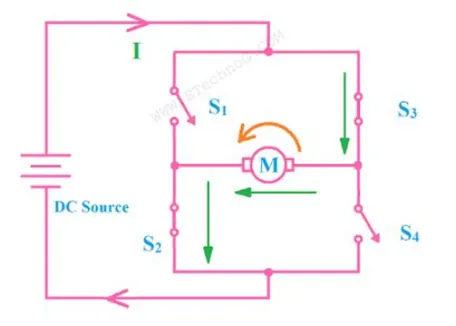
When S2 & S3 are fired negative voltage is applied to the motor which rotates Anti clockwise rotation the torque produced and armature current are negative value and diodes D1 & D4 operates s freewheeling diodes when S2 & S3 are switched OFF.
Forward Modelling –
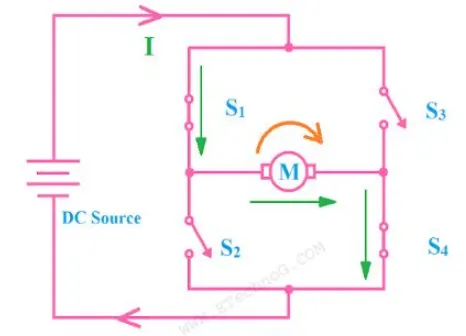
When S1 & S4 re fired positive voltage is applied to the motor which rotates in Clockwise rotation to the torque produced. Armature current are positive value thus power is positive and diodes D1 & D3 operates as freewheeling diodes when S1 & S4 are switched OFF.
The Four-Quadrant Chopper DC Drive (DC7) block
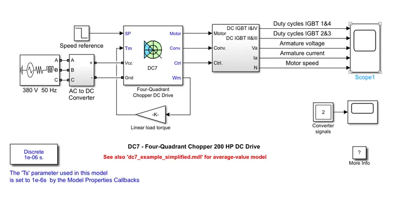
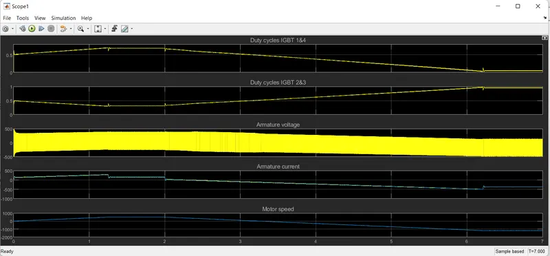
The 200 HP DC Motor is separately excited with 150 V DC filed voltage source. The armature voltage is provided by an IGBT converter controlled by 2 PI regulators. The converter is fed by a 550 V DC bus operator obtained by rectification of 380 V AC 50 Hz. Voltage source. In order to limit the DC bus voltage during dynamic breaking mode, a braking chopper has been added between the diode rectifier and the DC7 Block.
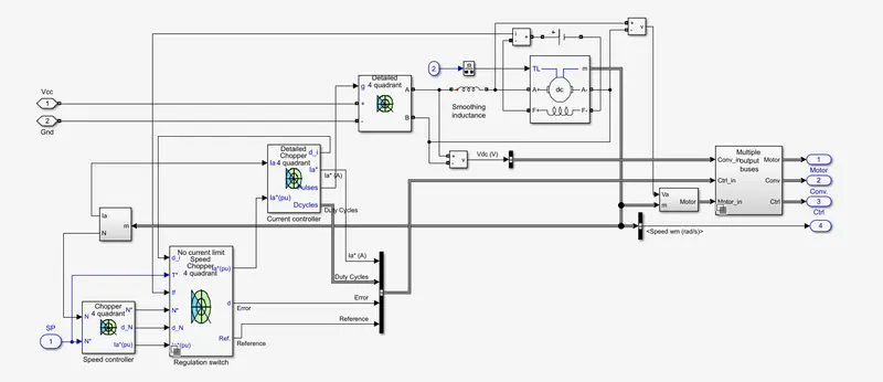
The first regulator is a speed regulator, followed by a current regulator. The speed regulator outputs the armature current reference (in p.u.) used by current controller in order to obtain electromagnetic torque needed to reach the desired speed. The speed reference change rate follows acceleration and deceleration ramps in order to avoid sudden reference changes that could cause armature over current and destabilize the system. the current regulator controls the armature current by computing the appropriate duty ratios of the 5KHz pulses of the 4 IGBT devices (Pulse Width Modulation). For proper system behaviour, the instantaneous pulse values of IGBT devices 1 & 4 are opposite to those IGBT devices 2 & 3. This generates the average armature voltage needed to obtain the desired Armature current, in order to limit the amplitude of the current oscillation, a smoothing inductance is placed in series with the armature circuit.
Comparison with H –Bridge Model –
Chopper is basically static power electronic device which converts the fixed DC voltage / power to variable DC voltage / power. It is nothing but a high speed switch which connects and disconnects the load from source at high rate to get variable or chopped voltage at the output.
Devices used in chopper are as follows
For Low power application – GTO, IGBT power BJT, power MOSFET
For High power application – Thyristor SCR.
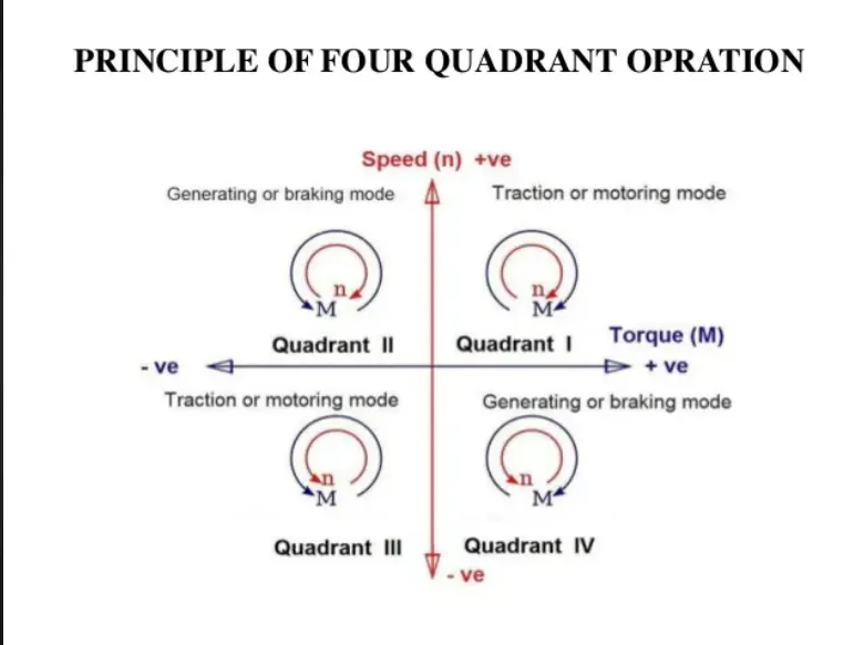
The four quadrant operation of any drives or DC motor means that the machine operates in four quadrants. They are Forward Braking, Forward Motoring, Reverse Motoring & Reverse Braking. The motor operates in two modes – motoring and braking. The motor drive capable of operating in both directions of rotation and of producing both motoring and regeneration is called the four quadrant variable speed drive.
In Motoring Mode, the machine works as, a motor and converts electrical energy into mechanical energy supporting its motion. The motor can work in both forward and reverse direction, i.e. motoring and braking conditions.
The product of angular speed and torque is equal to the power developed by the motor. For multi- Quadrant operation of drives the following conventions about the signs of torque and speed are used. When the motor is rotated in the forward direction the speed of the motor is considered positive. The drives which operate only in one direction forward speed will be their normal speed.
In loads involving up & down motions the speed of the motor which causes upward motion is considered to be in forward motion. For reversible drives, forward speed is chosen arbitrarily the rotation in the opposite direction gives reverse speed which is denoted by a negative sign.
The rate of change of speed positively in the forward direction or the torque which provides acceleration is known as positive motor torque. In the case of retardation, the motor torque is considered negative. Load torque is opposite to the positive motor torque in the direction.
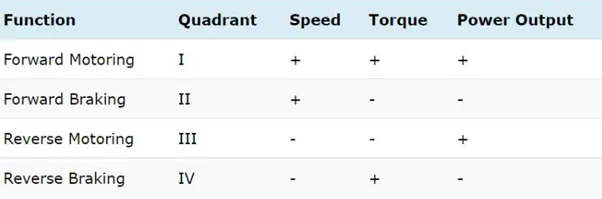
In the I Quadrant power developed is positive and machine is working as a motor supplying mechanical energy. The first quadrant operation is called Forward Motoring. II Quadrant is called Braking. In this quadrant the direction of rotation is positive and the torque is negative and thus the machine operates as the generator developing a negative torque which opposes the motion.
The kinetic energy of the rotating parts is available as electrical energy which is supplied back to the mains. In dynamic braking energy is dissipated in the resistance. The III Quadrant operation is known as reverse motoring. The motor works in the reverse direction. Both the speed and torque have negative values while the power is positive.
In the IV Quadrant the torque is positive and the speed is negative. This quadrant corresponds to braking in the reverse motoring mode.
Applications of 4 Quadrant operation –
Compressor, Pump, and fan type load requires operation in the I Quadrant only. As their operation is unidirectional, they are called one drive quadrant systems and the Transporter drive requires operation in both directions. If the regeneration is necessary application of all four quadrants may be required, if not then operation is restricted to quadrants I & III & thus dynamic braking / mechanical braking may be required.
The 4 Quadrant operation and its relationship to speed, torque and power output is summarized below in the table –
Comparison of 4 Quadrant DC7 Chopper block vs. DC motor BJT – H Bridge Block-
- Regenerative braking is possible.
- The current values are chopped but not continuous hence simulation takes less time.
- It is widely used in Automobile to control DC Motor speed and direction.
- To change the direction pf motor current signals are interrupted with one another.
DC Motor BJT – H Bridge Block –
- Regenerative braking isn’t possible but dynamic braking can be achieved.
- The current values are continuous.
- It is widely used in Robotics & Electro – Mechanical Device to control D.C. Motor speed and direction.
- To change the direction of the motor only polarity of the current is changed.
Overall in Automobile sector 4 – Quadrant chopper is preferred due to its high efficiency and ability to do regenerative braking which charges the battery whenever brakes are applied.
Q.2) Develop a 2-quadrant chopper using simulink & explain the working of the same with the relevant results. (Refer to article - Multiquadrant operation of motor )
Introduction-
The DC motor is used in many industrial applications requiring variable speed and load characteristics due to its ease of control. A chopper drive-based speed control is widely preferred as far as speed control is concerned. Choppers are mostly applied in electric cars, conversion of wind and solar energy, and DC motor regulators. A chopper uses the high speed to connect and disconnect from a source load. A fixed DC voltage is applied intermittently to the source load by continuously triggering the power switch ON/OFF. The period for which the power switch stays ON or OFF is referred to as the chopper’s ON and OFF state times, respectively.
The four-quadrant chopper is a chopper which can operate in all the four quadrants. The power can flow either from source to load or load to source in this chopper. In the first quadrant, a Class-E chopper acts as a Step-down chopper whereas in the second quadrant it behaves as a Step-up chopper. This type of chopper is also known as a Class-E or Type-E chopper. This article describes the working principle and operation of a Class-E chopper with the help of a circuit diagram.
What is a chopper?
A dc‐to‐dc converter, also known as dc chopper, is a static device which is used to obtain a variable dc voltage from a constant dc voltage source. Choppers are widely used in trolley cars, battery-operated vehicles, traction motor control, control of large numbers of dc motors, etc. They are also used as dc voltage regulators. Choppers are of two types: (1) Step‐down choppers, and (2) Step‐up choppers. In step‐down choppers, the output voltage will be less than the input voltage, whereas in step‐up choppers output voltage will be more than the input voltage
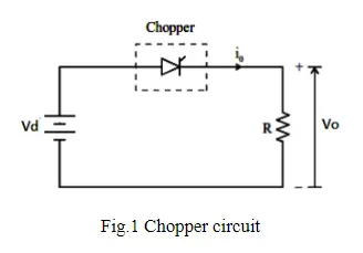
Chopper-Fed DC Motor Drive
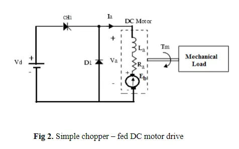
D.C motor is considered a SISO (Single Input and Single Output) system having torque/speed characteristics compatible with most mechanical loads. This makes a DC motor controllable over a wide range of speeds by proper adjustment of the terminal voltage
A simple chopper – fed DC motor drive is shown in Fig.2. The basic principle behind DC motor speed control is that the output speed of a DC motor can be varied by controlling armature voltage for speed below and up to rated speed keeping field voltage constant. The armature voltage can be controlled by controlling the duty cycle of the converter (here the converter used is a DC chopper)
Two Quadrant Chopper
In this type of Chopper, the average voltage will be always positive but the average load current might be positive or negative. The two Switches CH1 and CH2 should not be turned on simultaneously as the combined action may cause a short circuit in supply lines. For regenerative braking and motoring these type of chopper configuration is used.
We will always get a positive output voltage V0 as the freewheeling diode FD is present across the load. When the chopper CH1 is on the current flows from source to load. The inductor stores energy. When Ch1 turn OFF the freewheeling diode starts conducting and the output voltage v0 will be equal to Vs. The direction of the load current i0 will be reversed. The current i0 will be flowing towards the source. The load current will be negative when the CH2 is on. The current completes its path through diode D2.
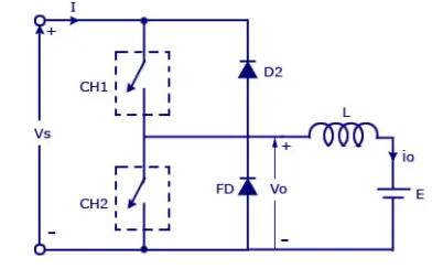
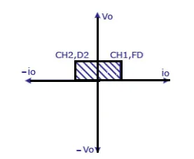
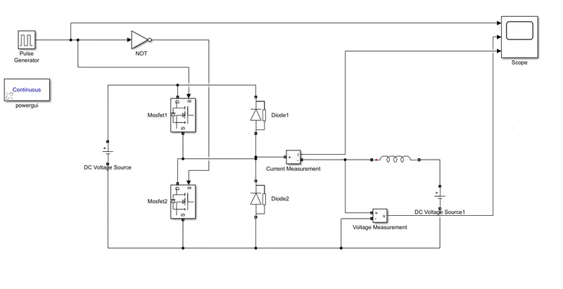
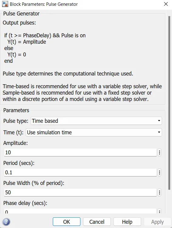
Fig-Simulink Model for 2-Quadrant Operation

Fig-Simulation Results
Q.3) Explain in a brief about operation of BLDC motor.
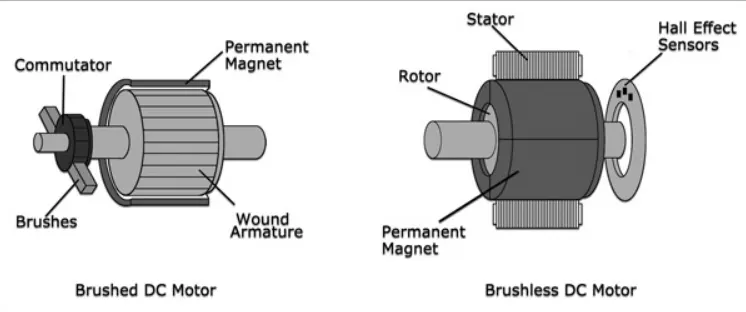
Fig- Construction of Brushed DC Motor & Brushless DC motor
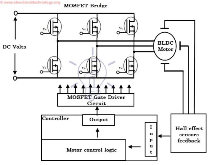
What is a Brushless DC or BLDC Motor?
A Brushless DC Motor, BLDC accomplishes commutation electronically using rotor position feedback to determine when to switch the current. The BLDC motor is electrically commutated by power switches instead of brushes. The structure of Brushless DC Motor, BLDC is shown in figure below.
In simple words, a BLDC has no brushes and commutator for having unidirectional torque rather integrated inverter / switching circuit is used to achieve unidirectional torque. That is why these motors are, sometimes, also referred as Electronically Commutated Motors.
These types of motors are highly efficient in producing a large amount of torque over a vast speed range. In brushless motors, permanent magnets rotate around a fixed armature and overcome the problem of connecting current to the armature. Commutation with electronics has a large scope of capabilities and flexibility. They are known for smooth operation and holding torque when stationary.
Construction of BLDC Motor:
Like any other electric motor, a BLDC motor also has a stator and a rotor. Here we will consider Stator and Rotor each separately from construction point of view.
BLDC Stator:
There are three types of the BLDC motor:
- Single-phase
- Two-phase
- Three-phase.
Stator for each type has the same number of windings. The single-phase and three-phase motors are the most widely used. The simplified cross section of a single-phase and a three-phase BLDC motor is shown in figure below. The rotor has permanent magnets to form two magnetic pole pairs, and surrounds the stator, which has the windings.
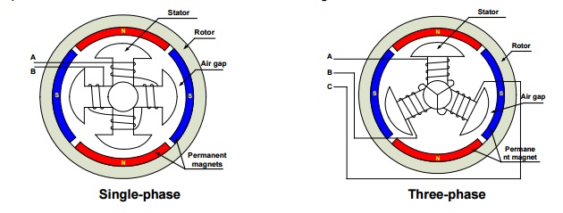
A single-phase motor has one stator winding wound either clockwise or counter-clockwise along each arm of the stator to produce four magnetic poles as shown in above figure.
A three phase BLDC motor has three windings. Each phase turns on sequentially to make the rotor revolve.
Rotor:
A rotor consists of a shaft and a hub with permanent magnets arranged to form between two to eight pole pairs that alternate between north and south poles. Figure below shows cross sections of three kinds of magnets arrangements in a rotor.
Working of BLDC Motor:
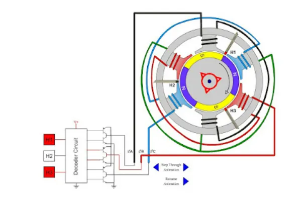
BLDC Motor operation is based on the attraction or repulsion between magnetic poles. Using the three-phase motor as shown in figure below, the process starts when current flows through one of the three stator windings and generates a magnetic pole that attracts the closest permanent magnet of opposite pole.
The rotor will move if the current shifts to an adjacent winding. Sequentially charging each winding will cause the rotor to follow in a rotating field. The torque in this example depends on the current amplitude and the number of turns on the stator windings, the strength and the size of the permanent magnets, the air gap between the rotor and the windings, and the length of the rotating arm.
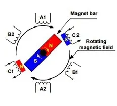
The high power transistors are used to activate electromagnets for the shaft turns. The controller performs power distribution by using a solid-state circuit.
Advantage of BLDC Motor:
Compared with a brushed DC motor or an induction motor, the BLDC motor has many advantages:
- Higher efficiency and reliability
- Lower acoustic noise
- Smaller and lighter
- Greater dynamic response
- Better speed versus torque characteristics
- Higher speed range
- Longer life
Disadvantages of a BLDC Motor:
- BLDC motor cost more than a brushed DC motor.
- The limited high power could be supplied to BLDC motor, otherwise, too much heat weakens the magnets and the insulation of winding may get damaged.