Project - Speed Control of a Direct Current (DC) motor
DIRECT CURRENT MOTOR
A DC motor is a Electrical motor that converts direct current (DC) electrical energy into mechanical energy. The most common types rely on the forces produced by induced magnetic fields due to flowing current in the coil.
Working Principle of DC Motor
When kept in a magnetic field, a current-carrying conductor gains torque and develops a tendency to move. In short, when electric fields and magnetic fields interact, a mechanical force arises. This is the principle on which the DC motors work.
Types Of DC Motors-
1) DC Series Motor
2) DC Shunt Motor
3) Compound DC Motor
4) Permanent Magnet DC Motor
Construction of DC Motor-
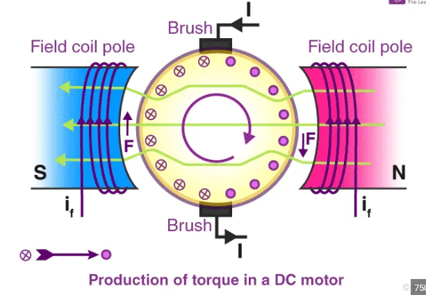
The commutator of a DC motor is a cylindrical structure that is made of copper segments stacked together but insulated from each other using mica. The primary function of a commutator is to supply electrical current to the armature winding. The brushes of a DC motor are made with graphite and carbon structure.
The brushes of a DC motor are made with graphite and carbon structure. These brushes conduct electric current from the external circuit to the rotating commutator. Hence, we come to understand that the commutator and the brush unit are concerned with transmitting the power from the static electrical circuit to the mechanically rotating region or the rotor.
Speed Control Techniques of DC Motor-
The speed of a DC motor (N) is equal to
N = K (V – IaRa)/ ø Where, K is a constant.
This implies three things:
Speed of the motor is directly proportional to supply voltage.
The Speed of the motor is inversely proportional to armature voltage drop.
The motor speed is inversely proportional to the flux due to the field winding.
Speed control of DC motor methods-
1) Flux control method
2) Armature control method
3) supply voltage control method
PID Controller-
A proportional–integral–derivative controller (PID controller or three-term controller) is a control loop mechanism employing feedback that is widely used in industrial control system and a variety of other applications requiring continuously modulated control. A PID controller continuously calculates an error value e(t) as the difference between a desired setpoint and a measured process variable and applies a correction based on proportional, integral & deravative term.
PID Controller for DC motor-
The Discrete PID controller is used to measure the Speed, Torque and Voltage of the DC motor and then send it back as feedback.
AIM- Speed control of DC Motor by using PID Controller
Design a PID controller to regulate the speed of the DC Motor
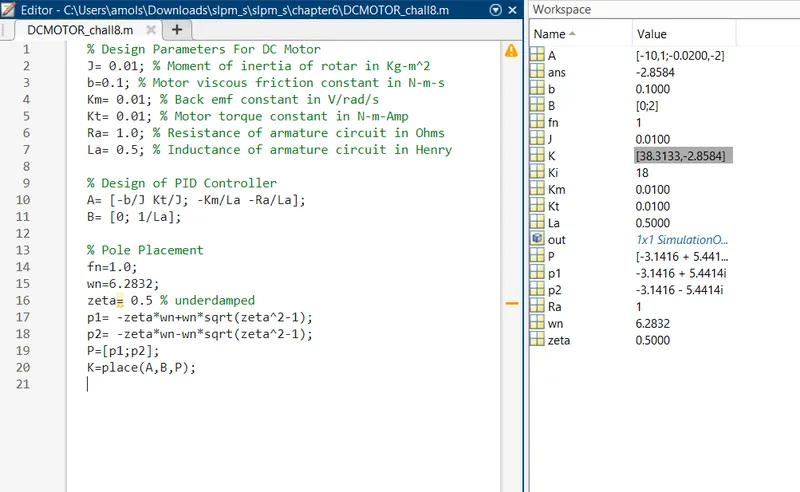
PID controller is been build by finding the values of Kp, Kd by using Matlab command 'place'.
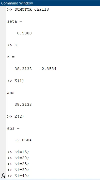
The value of Ki is set manually to find out the behaviour of the system at different values of Ki.
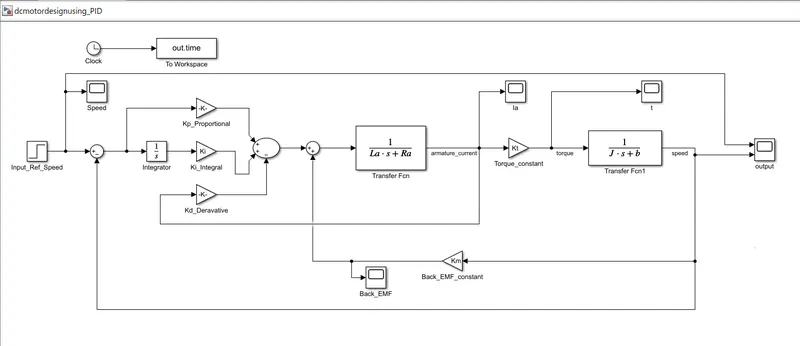
Step input block is been used as reference speed input.
The Editor script file is been build consisting of design parameters.
Model is been build to regulate the speed of the DC Motor by using PID Controller.
command window for selecting different values of Ki.
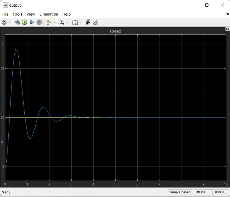
the reference speed is kept to 20.
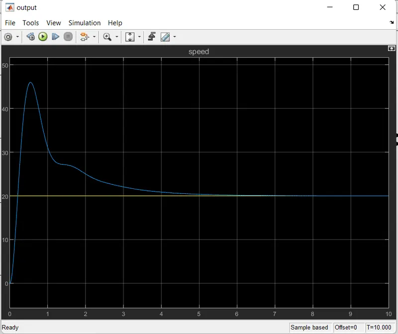
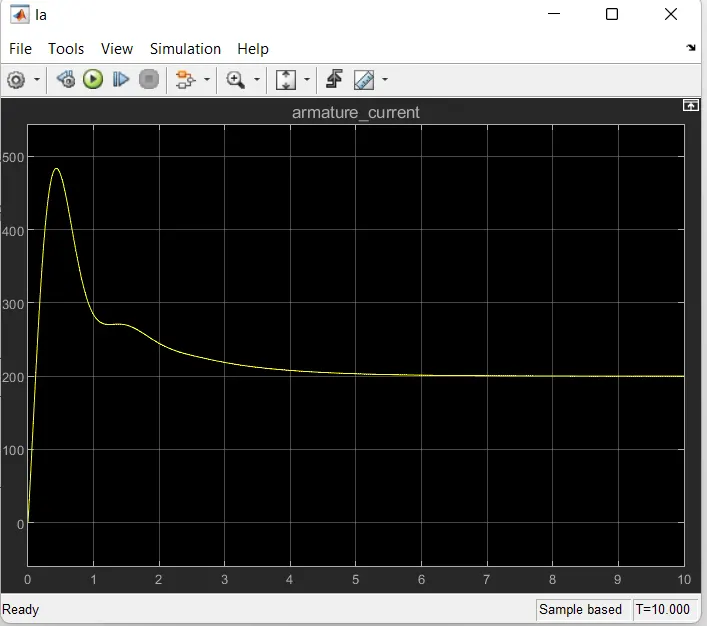
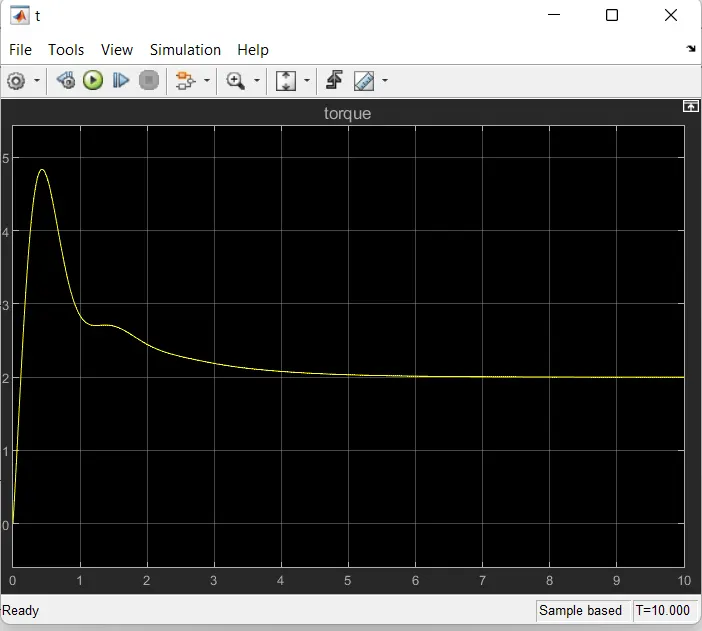
different values of Ki are been taken and accordingly waveforms are been generated as shown below.the waveforms for Output, Current Ia, Torque t & Back EMF are shown below.
for Ki=15,
for this value of Ki the system settles at 5.5 sec with less oscillations. Though it has less oscillations but its settling time is more. The settling time should be 2-3 secs.
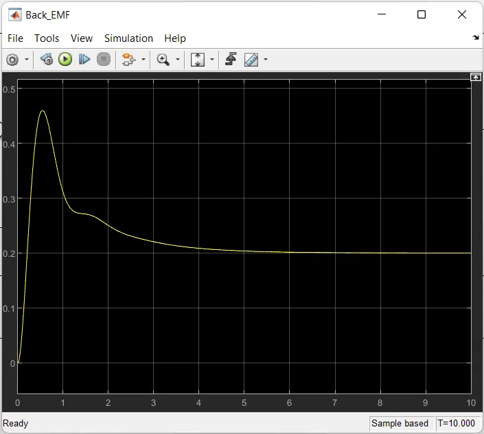
For Ki=20,
For this value of Ki the settling time is near about 4 secs. the waveform has a little oscillations i.e overshoot and undershoot before settling at stable state.
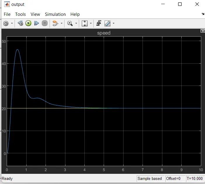
AT Ki= 30,
For this value of Ki settling time has quite been reduced it has been reduced to 3.5 secs, but system has oscillations before comming to stability.
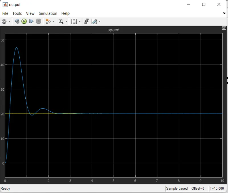
AT Ki=40,
the system settles nearabout 3 sec but has overshoots and undershoots befor settling. Generally overshoots upto 10% are allowable. The system response is fast.
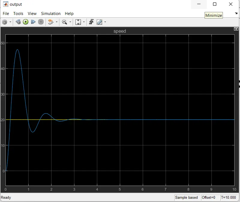
At Ki=50,
at this value of Ki the response is fast but with more oscillations. As we go on increasing the value of Ki the system behaves faster, with oscillatons and low settling time.
Conclusion-:
The model is been simulated using different values of Ki. There were less oscillations when Ki was kept low but the settling time was more. For higher values of Ki the system response was faster with more oscillations and lesser settling time. It is required that the system must settle near about 4 secs with less oscillations. So it can be conclued that the values of PID Controller for better results must be,
Kp= +38.3133
Kd= -2.8584
Ki= +40
[Kp Ki Kd] = [+38.3133, +40, -2.8584 ] System performs best under such parameters.
Key Highlights-
A proportional controller (Kp) will have the effect of reducing the rise time and will reduce ,but never eliminate the steady state error.
An integral control (Ki) will have the effect of eliminating the steady-state error, but it may make the transient response worse.
A derivative control (Kd) will have the effect of increasing the stability of the system, reducing the overshoot, and improving the transient response.