Week-7 Challenge: DC Motor Control
QA:1(A)
Speed Control of a DC Motor using BJT H-Bridge -
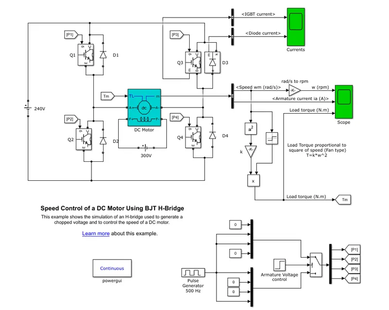
- The Bipolar Junction Transistor (BJT) when used for power switching applications, operates as an IGBT.
- When it is conducting (BJT operating in the saturated region), a forward voltage Vf is developed between collector and emitter (in the range of 1 V).
- Therefore, the IGBT block can be used to model the BJT device.
- The IGBT block does not simulate the gate current controlling the BJT or IGBT.
- The switch is controlled by a Simulink signal (1/0).
- It simulates a fan type load (where Load torque is proportional to square of speed).
- The armature mean voltage can be varied from 0 to 240 V when the duty cycle (specified in the Pulse Generator block) is varied from 0 to 100%.
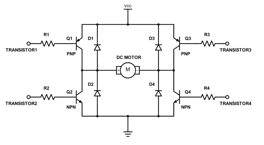
- The H-bridge consists of four BJT/Diode pairs (BJT simulated by IGBT models).
- Two transistors are switched simultaneously: Q1 and Q4 or Q2 and Q3.
- When Q1 and Q4 are fired, a positive voltage is applied to the motor and diodes D2-D3 operate as free-wheeling diodes when Q1 and Q4 are switched off.
- When Q2 and Q3 are fired, a negative voltage is applied to the motor and diodes D1-D4 operate as free-wheeling diodes when Q2 and Q3 are switched off.
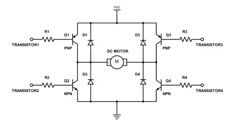
- Diodes are given for the current to free wheel as the DC motor is a RLE load where the current cannot change direction instantaneously.We all know that transistor works as switch. For NPN transistor if we give enough +Ve input to base it will turn ON (Saturation region) and if we give 0 input it will be turned OFF (Cut off region). So in this circuit if Q1 and Q4 are turned ON simultaneously the motor will rotate forward and if Q2 and Q3 are turned ON then motor will rotate in reverse direction.
*Here it contains 4 switching elements Q1,Q2,Q3,Q4 ie IGBT's with the load at the center in an H-like configuration.
*The IGBT consists of 3 terminals;collector(C),emitter(E) and gate(G).
*The current flows from Collector to Emitter & the gate terminal is controlled by the pulses using the pulse generator.
*The top portion of the bridge is connected to a supply source here battery in this case while the bottom portion is connected to ground.
*The free wheeling diodes D1,D2,D3,D4 are connected across each of switching elements & are used as a safety purpose of the circuit.
* Now, if we trigger or turn ON switches QI & Q4, the current starts flowing from source to load & in this case the motor starts rotating in forward direction.So in this mode we have forward motoring & forward braking.
*In the other state if we turn ON Q2 & Q23 switches, the current will start flowing from load to source & thus the motor will starts rotating in the reverse direction.So in this mode we have reverse motoring & reverse braking.
*in this circuit we have to be cautious that switches Ql & Q2 should not be triggered together if this happen it will create a very low resistance path thus short circuiting the circuit & will cause damage to the circuit or circuit may burn.Similary switch Q3 & Q4 should also be not triggered together.
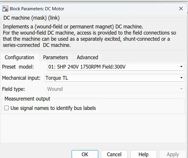
*In motor circuit,armature terminals are connected to a 240V supply while field windings are connectedto a 300V supply.
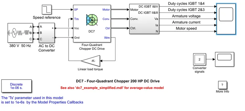
The motor starts in the positive direction with a duty cycle of 75% (mean DC voltage of 180V). At t= 0.5 sec., the armature voltage is suddenly reversed and the motor runs in the negative direction.
'Scope' shows motor speed, armature current and load torque and 'Currents' shows currents flowing in BJT Q3 and diode D3.
The duty cycles are set in pulse generator block with 75 % duty cycle-
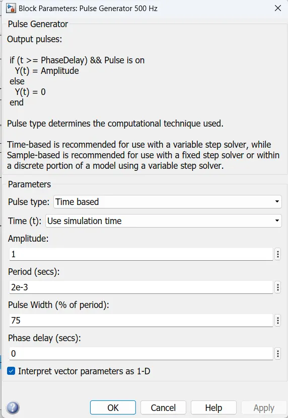
When the simulation is run for the first time , without changing any parameters , keeping all parameters same the results obtained are discussed below-
The max speed which can be achieved is about 951 rpm
The maximum torque which is obtained is 6.04Nm and minimum torque is -6.04 Nm
'Currents' shows currents flowing in Bipolar Junction Transistor Q3 and diode D3. Adding of diodes in the Forward direction for the transistors, to give a path for the current to take to release this energy. Without diodes, it risk that the voltage rises and damages the transistors.
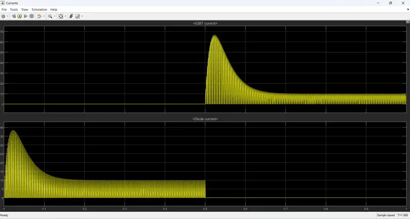
From the above plot, observed that '0s -0.5 s' Current flow Through 'Diode D3' and '0.5s - 1s' Current will flow through 'BJT Q3'.
The Ouput from the DC motor is Speed ("rad/s"is converterd into "rpm") and Armature Current(A) is connected with 'Scope'. where, Load Torque(T) is directly proportional to Square of Speed.
T∝ω^2
T=k⋅ω^2
Output from the Speed(ω) is multiplied with constant(k) gives Load Torque(T) and it is also connected with 'Scope'. 'Scope' shows motor speed, armature current and load torque.
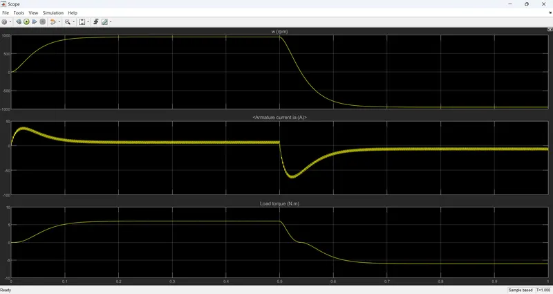
In the above plot, Armature current has sudden rise and drop when the motor changes direction from forward to reverse motion.
QA:1(B)
Basic operational voltage equation of a DC motor is given as
E = Eb + IaRa and hence, Ia = (E - Eb) / Ra
Now, when the motor is at rest, obviously, the back emf Eb = 0. Hence, armature current at the moment of starting can be given as Ia = E / Ra. In practical DC machines, armature resistance is basically very low, generally about 0.5 Ω. Therefore, a large current flows through the armature during starting. This current is large enough to damage the armature circuit.
The armature current spikes at each duration of switching when the armature voltage is reversed.
This is due to the transient switching between the two states of positive and negative voltage applied to the motor instantenously. This switching causes the input-surge current or inrush currents. The maximum instantaneous input current drawn by an electrical device when first turned on is known as Inrush current.
QA:1 (C)
Four quadrant chopper
WORKING :
The circuit of the 4 Quadrant chopper also known as class E chopper basically consists of four semiconductor switches CH1 and CH4 and 4 diodes D1 to D4 connected in anty-parrallel manner At the first quadrant operation CH1 is made on ,for 2nd quadrant operation CH2 is made on and continues as cyclic order as shown below
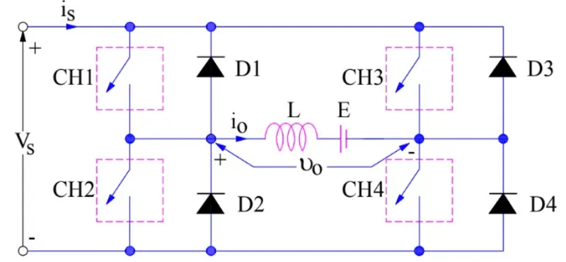
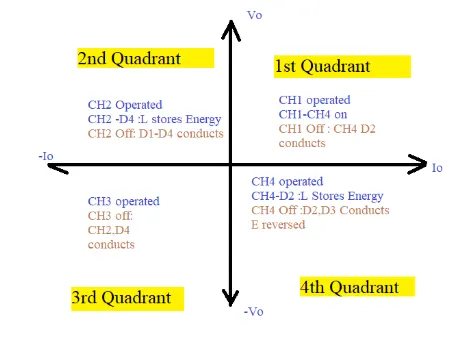
*1st quadrant operation ,CH4 is kept on and CH3 is kept off and CH1 is operatd ,Both CH1 and CH4 are on simultaneously load gets directly connected to the source ,so the output voltage becomes equal to the source voltage,CH1 is switched off.
*2nd quadrant operation: To understand quadrant ,while keeping the CH1,CH3 and CH4 off,when CH2 is on ,the DC source voltage vs ,as load current through CH2,D4,E and L.inductor L stores energy during the on period of CH2.
*3rd Quadrant operation:in this quadrant operation both the load voltage and load current should be -ve,The current and voltage are assumed +ve if their direction matches with what shown in the circuit diagram.
*4th Quadrant operation: by obtaning CH4,D2,L and E inductance L energy during the time CH4 is on,when CH4 is made off,current is fed off,current is fed back to the source through diodes D2,D3 ,here load voltage is -ve but the load current is always +ve.This leads to chopper operation operation in fourth quadrant.
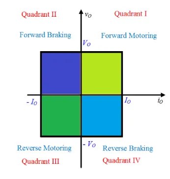
The operation of a four-quadrant chopper or Class-E chopper is summarized in the figure below:
| H bridge | Four Quadrant chopper DC drive |
| Only Two quadrants of operation are possible. They are Forward motoring and reverse motoring | It can operate in all four quadrants (forward motoring, reverse regeneration, reverse motoring, and forward regeneration) |
| Higher armature current ripple. | Lower armature current ripple due to high switching frequency of DC-DC coverters |
| Less complex | More complex |
| Simulation is continuous and simulation time is more | Discrete and Simulation time is less |
| Widely Used in Robotics | Widely used in Automobile |
QA:2) Two Quadrant chopper:
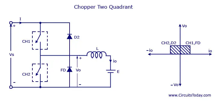
* In this type of Chopper, the average voltage will be always positive but the average load current might be positive or negative.
*The two Switches CH1 and CH2 should not be turned on simultaneously as the combined action may cause a short circuit in supply lines.
*For regenerative braking and motoring these type of chopper configuration is used.
*We will always get a positive output voltage V0 as the freewheeling diode FD is present across the load.
* When the chopper CH1 is on the current flows from source to load.
*The inductor stores energy. When Ch1 turn OFF the freewheeling diode starts conducting and the output voltage v0 will be equal to Vs.
* The direction of the load current i0 will be reversed. The current i0 will be flowing towards the source.
*The load current will be negative when the CH2 is on. The current completes its path through diode D2.
The simulink model for the 2 quadrant chopper is shown below :
Working :
- For the 2 quadrant chopper two MOSFETs CH1 and CH2 are used with diodes FD1 and FD2 connected in parallel to MOSFETs.
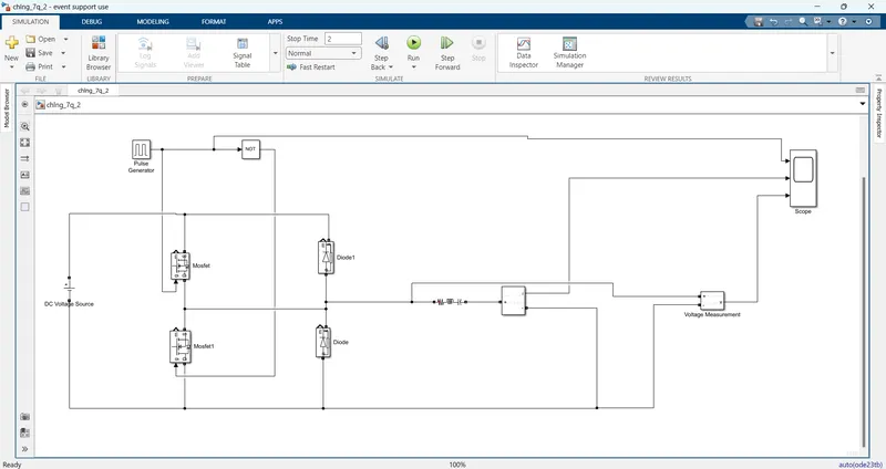
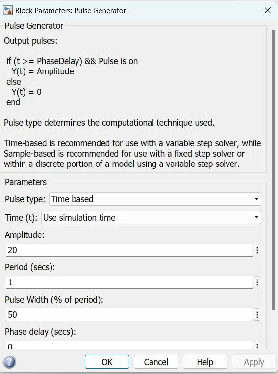
*For the switching of MOSFETs gate pulse is give using pulse generator with parameters given in the figure bellow
*For the motor load, a inductor is taken with the value of 1e^-3.
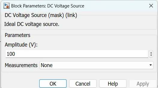
*A dc voltage source (V) of 100 V is provided for the circuit .
*During first pulse, CH1 is on and the current flows from source to load.
*During this inductor stores senergy.
*When CH1 turns OFF, the FD starts conducting and direction of load current is reversed.
*When CH2 turns ON, the current will be flowing towards the source and the load current will be negative.
*The current completes its path through diode D2.
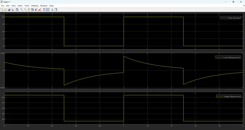
Result:
Hence, we could see that the voltage is always positive but the current becomes both positive and negative. Hence, the Type C chopper is simulated and verified.
QA:3
Operation of BLDC motor :
* Also known as brush type D.C motor with electronic commutator.
*This is a three terminal motor with one rotor and two stators.
*This should have a power converter or electronic commutator.
*It is a synchronous motor using a direct current (DC) electric power supply.
*It uses an electronic controller to switch DC currents to the motor windings producing magnetic fields which effectively rotate in space and which the permanent magnet rotor follows.
*unlike conventional brushed type dc motor,where the brush is connected with armature,its not there in the BLDC motor.
Construction of BLDC Motor;
*In this motor, the permanent magnets attach to the rotor. The current-carrying conductors or armature windings are located on the stator.
*They use electrical commutation to convert electrical energy into mechanical energy.
*The main design difference between a brushed and brushless motors is the replacement of mechanical commutator with an electric switch circuit.
*A BLDC Motor is a type of synchronous motor in the sense that the magnetic field generated by the stator and the rotor revolve at the same frequency.
*The controller adjusts the phase and amplitude of the DC current pulses to control the speed and torque of the motor.
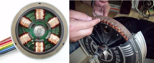
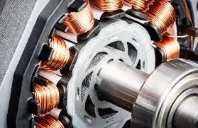
Working Principle :
- BLDC motor works on the principle similar to that of a conventional DC motor, i.e., the Lorentz force law which states that whenever a current carrying conductor placed in a magnetic field it experiences a force.
- As a consequence of reaction force, the magnet will experience an equal and opposite force. In the BLDC motor, the current carrying conductor is stationary and the permanent magnet is moving.
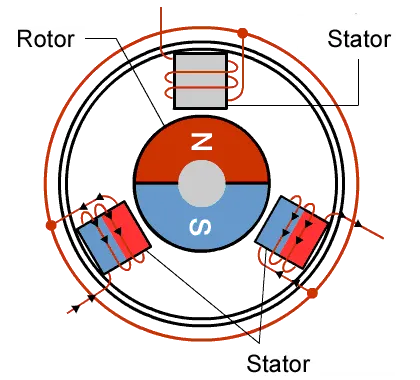
- When the stator coils get a supply from source, it becomes electromagnet and starts producing the uniform field in the air gap.
- Though the source of supply is DC, switching makes to generate an AC voltage waveform with trapezoidal shape. Due to the force of interaction between electromagnet stator and permanent magnet rotor, the rotor continues to rotate.
- With the switching of windings as High and Low signals, corresponding winding energized as North and South poles.
- The permanent magnet rotor with North and South poles align with stator poles which causes the motor to rotate.
Advantages:
- Less overall maintenance due to absence of brushes
- Reduced size with far superior thermal characteristics
- Higher speed range and lower electric noise generation.
- It has no mechanical commutator and associated problems
- High efficiency and high output power to size ratio due to the use of permanent magnet rotor
- High speed of operation even in loaded and unloaded conditions due to the absence of brushes that limits the speed
- Smaller motor geometry and lighter in weight than both brushed type DC and induction AC motors.
- Long life as no inspection and maintenance is required for commutator system
- Higher dynamic response due to low inertia and carrying windings in the stator
- Less electromagnetic interference
- Low noise due to absence of brushes
Limitations of BLDC Motor:
- These motors are costly
- Electronic controller required control this motor is expensive
- Requires complex drive circuitry
- Need of additional sensors
Types of Brushless DC Motors
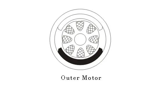
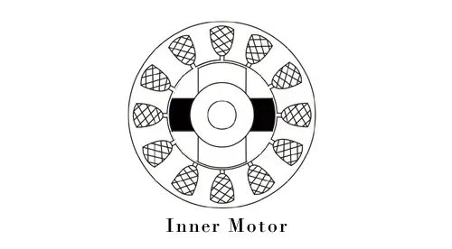
Basically, BLDC are of two types, one is outer rotor motor and other is inner rotor motor. The basic difference between the two is only in designing, their working principles are same.
Inner Rotor Design
In an inner rotor design, the rotor is located in the centre of the motor and the stator winding surround the rotor. As the rotor is located in the core, rotor magnets do not insulate heat inside and heat get dissipated easily. Due to this reason, inner rotor designed motor produces a large amount of torque and validly used.
Outer Rotor Design
In outer rotor design, the rotor surrounds the winding which is located in the core of the motor. The magnets in the rotor trap the heat of the motor inside and do not allow to dissipate from the motor. Such type of designed motor operates at lower rated current and has low cogging torque.