Week-7 Challenge: DC Motor Control
Introduction:
Power Semiconductor Devices:
Power electronic converters take electrical energy from the power system and turn it into a suitable form needed by a motor. The power electronic converter may be determined according to the power source and the driving motor. Power semiconductor devices are widely used in automotive power electronic systems and often these systems are efficient, cost, and size. Active power semiconductor switches
such as MOSFETS and IGBTS serve as load drivers for motors. solenoids, ignition coil relays, heaters, lamps, and other automotive loads. Diodes are used in automotive systems to rectify AC generated by the alternator, provide a freewheeling current path for IGBTs or MOSFETs in DC/DC converters, and suppress voltage transients.
Transistor
A transistor is a miniature semiconductor that regulates or controls current or voltage flow, amplifying and generating these electrical signals and acting as a switch/gate for them. Typically, transistors consist of three layers, or terminals, of semiconductor material, each of which can carry a current.
Transistor basically has 3 parts:
- Base: used to activate the transistor
- Emitter: This is the positive lead of the transistor
- Collector: This is the negative lead of the transistor
Transistors are commonly used in the digital circuit as electronic switches, either in an ‘’on’’ or ’off’’ state, both for high-power applications such as swathed-mode power switches and low-power applications such as logic gates.
Based on how they are used, transistors can be classified into:
- BJT (Bipolar junction transistors)
- FET (Field effective Transistor)
Bipolar Junction Transistor:
The three terminals of BJT are the base, emitter, and collector. A very small current flowing Between the base and the emitter can control a larger flow of current between the collector and emitter terminal.
BJTs are divided into:
- NPN
- PNP
Power MOSFET (Metal oxide semiconductor field-effect transistors):
The power MOSFET is a type of MOSFET. The operating principle of power MOSFET is similar to the MOSFET. The power MOSFET is very special to handle high-level powers. It shows the high switching speed and by comparing It to normal MOSFET.
The power MOSFETs are used in the power supplies
- DC to DC converters
- Low voltage motor controllers.
- These are widely used in low-voltage switches which are less than 200v.
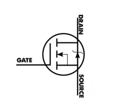
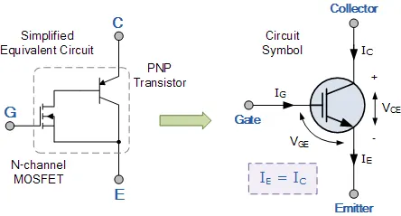
IGBT (Insulated Gate Bipolar Transistor):
The Insulated Gate Bipolar Transistor also called an IGBT for short, is something of a cross between a conventional Bipolar Junction Transistor, (BJT) and a Field Effect Transistor, (MOSFET) making it ideal as a semiconductor switching device.
The IGBT Transistor takes the best parts of these two types of common transistors, the high input impedance and high switching speeds of a MOSFET with the low saturation voltage of a bipolar transistor, and combines them together to produce another type of transistor switching device that is capable of handling large collector-emitter currents with virtually zero gates current drive.
1. A. Explain a MATLAB demo model named ‘Speed control of a DC motor using BJT H-bridge’.
H Bridge circuit
In general, an H – the bridge is a rather simple circuit, containing four switching elements With the load at the entrance, in an H- live configuration control a DC motor to go backward or forward. The load is kept in the center.
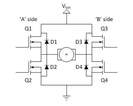
In general, a very simple circuit has 4 switching elements so this switching element is Here MOSFET. Of these 3 terminals, one terminal connects positive potential another negative Potential, 3rd the terminal pulse controls the signal in order to switch on devices. There is connect the A side and B side, a side connected with 2 switches and a B side connected With 2 switches .1 st condition current through that current should be following positive Potential or sauce throve DC switched to load throat negative potential in order to close the circuit.
Static Operation
The basic operating mode of an H-bridge is fairly simple: if Q1 and Q4 are turned on, the left lead of the motor will be connected to the power supply, while the right lead is connected to the ground. Current starts flowing through the motor which energizes the motor in (let’s say) the forward direction and the motor shaft starts spinning
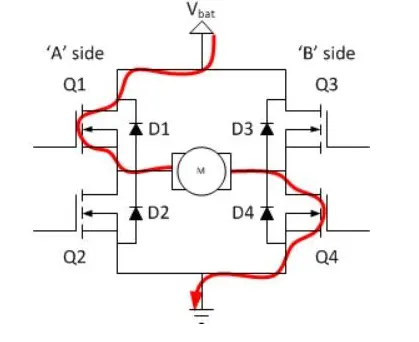
If Q2 and Q3 are turned on, the reverse will happen, the motor gets energized in the reverse direction, and the shaft will start spinning backward.
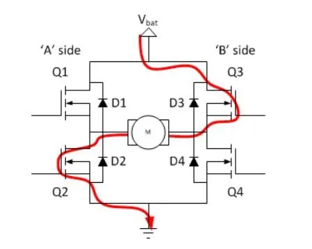
in a bridge, you should never close both Q1 and Q2 (or Q3 and Q4) at the same time. If you did that, you just have created a really low-resistance path between power and GND, effectively short-circuiting your power supply. This condition is called ‘shoot-through and is an almost guaranteed way to quickly destroy your bridge or something else in your circuit.
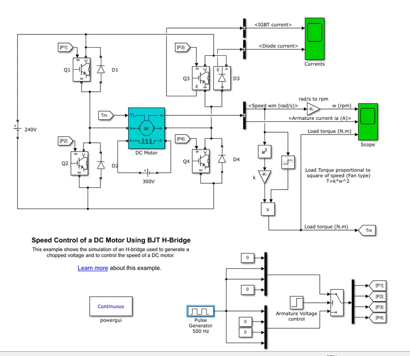
B. Comment on the armature current shoot-up from the scope results.
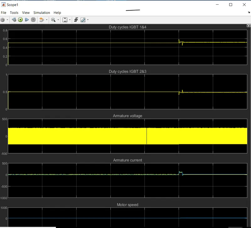
- Initially, we run a MATLAB demo ‘Speed control of a DC motor using BJT H-bridge’ with all its default values and different pulse widths (duty cycle) 75%, 50%, and 40%.
- From this, we get the following three plot results-
- 75%
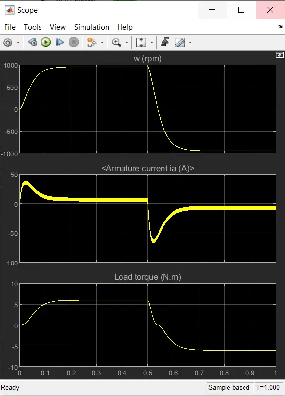
- 50%
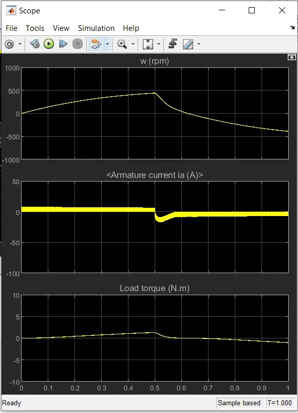
- 40%
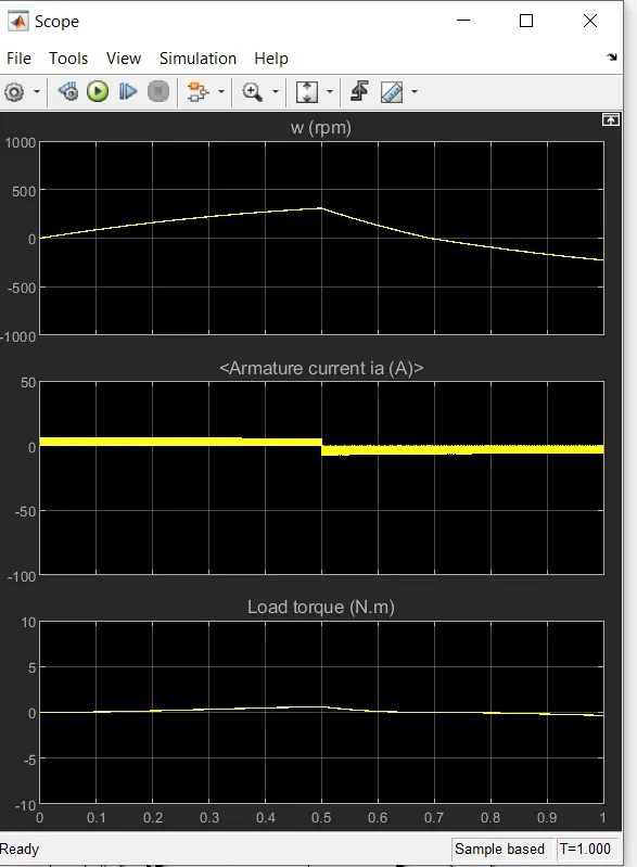
- From 1st plot, we can see that the current plot has initially a very high value and then becomes steady and after that shows the same path in the -ve direction.
- In these three plots, the value of this current shoot-up is decreasing and the 3rd plot has an almost smooth current flow.
- To get a steadier and smoother current flow we need to decrease and control the duty cycle.
- This shoot-up happens because of the switching in the circuit that causes heat losses during switching. To avoid these losses, we use HEAT SINK material to dissipate the heat. From this, the motor can change its direction of rotation easily and very smoothly.
C. Refer to the help section of ‘The Four-Quadrant Chopper DC Drive (DC7) block’. Compare it with the H-bridge model.
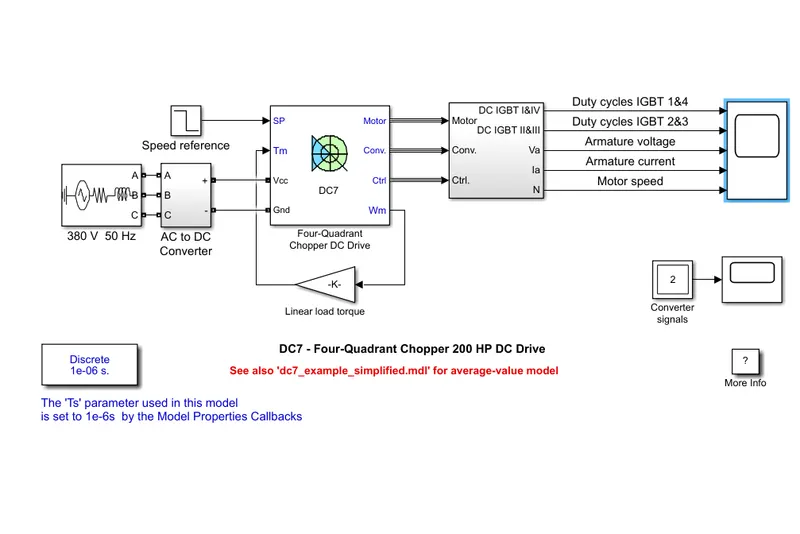
The first regulator is a speed regulator, followed by a current regulator. The speed regulator outputs the armature current reference (in p.u.) used by the current controller in order to obtain the electromagnetic torque needed to reach the desired speed.
The speed reference change rate follows acceleration and deceleration ramps in order to avoid sudden reference changes that could cause armature over-current and destabilize the system.
A dc‐to‐dc converter, also known as a dc chopper, is a static device that is used to obtain a variable dc voltage from a constant dc voltage source. Choppers are widely used in trolley cars, battery-operated vehicles, traction motor control, control of large numbers of dc motors, etc. They are also used as dc voltage regulators. Choppers are of two types: (1) Step‐down choppers, and (2) Step‐up choppers. In step‐down choppers, the output voltage will be less than the input voltage, whereas in step‐up choppers output voltage will be more than the input voltage
Comparison:
|
Four-Quadrant Chopper DC Drive |
H-bridge model |
|
To change the motor direction the polarity is changed |
To change the motor direction the current signal has to be interrupted. |
|
It has broader torque and power output ranges |
It uses a single pulse generator which gives narrow torque and power output range. |
|
Up to 400v can be achieved. |
Up to 350v can be achieved. |
|
In this, the current has chopped values. |
In this, the current has continuous values. |
|
Regenerative braking is possible |
Regenerative braking is not possible |
2. Develop a 2-quadrant chopper using Simulink & explain the working of the same with the relevant results. (Refer to the article - Multiquadrant operation of the motor )
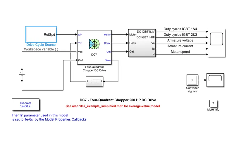
1) 380V 50HZ with a DC source.
2) we need to replace the AC battery source with a DC battery to simulate the working of an electric vehicle
3) to simulate the vehicle parameters we need to equate a relation between torque and motor speed which is given by
TTR=24.7+0.0015w2"
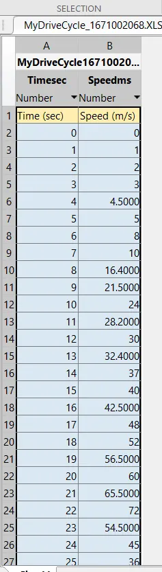
4) now we need to simulate a drive cycle that can be imported from an excel file by creating a drive cycle.
after making all the changes the model will look something like this
3. Explain in a brief the operation of the BLDC motor.
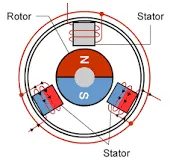
the BLDC motor, the current-carrying conductor is stationary and the permanent magnet is moving. When the stator coils get a supply from the source, it becomes an electromagnet and starts producing the uniform field in the air gap.
The brushes change the polarity of the pole to keep the rotation on of the armature. The basic working principle for the brushed DC motor and for the brushless DC motor is the same i.e. internal shaft position feedback.
A Brushless DC motor has only two basic parts: the rotor and the stator. The rotor is the rotating part and has rotor magnets whereas the stator is the stationary part and contains stator windings. In BLDC permanent magnets are attached to the rotor and move the electromagnets to the stator. The high-power transistors are used to activate electromagnets for the shaft turns. The controller performs power distribution by using a solid-state circuit.
Types of Brushless DC Motors
Basically, BLDCs are of two types, one is an outer rotor motor and the other is an inner rotor motor. The basic difference between the two is only in design, their working principles are the same.
Inner Rotor Design
In an inner rotor design, the rotor is located in the center of the motor and the stator winding surrounds the rotor. As the rotor is located in the core, rotor magnets do not insulate heat inside and the heat gets dissipated easily. Due to this reason, the inner rotor-designed motor produces a large amount of torque and is validly used.
Outer Rotor Design
In outer rotor design, the rotor surrounds the winding which is located in the core of the motor. The magnets in the rotor trap the heat of the motor inside and do not allow it to dissipate from the motor. Such a type of designed motor operates at a lower rated current and has low cogging torque.
Advantages of Brushless DC Motor
The advantages of a BLDC motor are:
- Brushless motors are more efficient as its velocity is determined by the frequency at which current is supplied, not the voltage.
- As brushes are absent, the mechanical energy loss due to friction is less which enhanced efficiency.
- BLDC motor can operate at high-speed under any condition.
- There is no sparking and much less noise during operation.
- More electromagnets could be used on the stator for more precise control.