Week-6 Challenge: EV Drivetrain
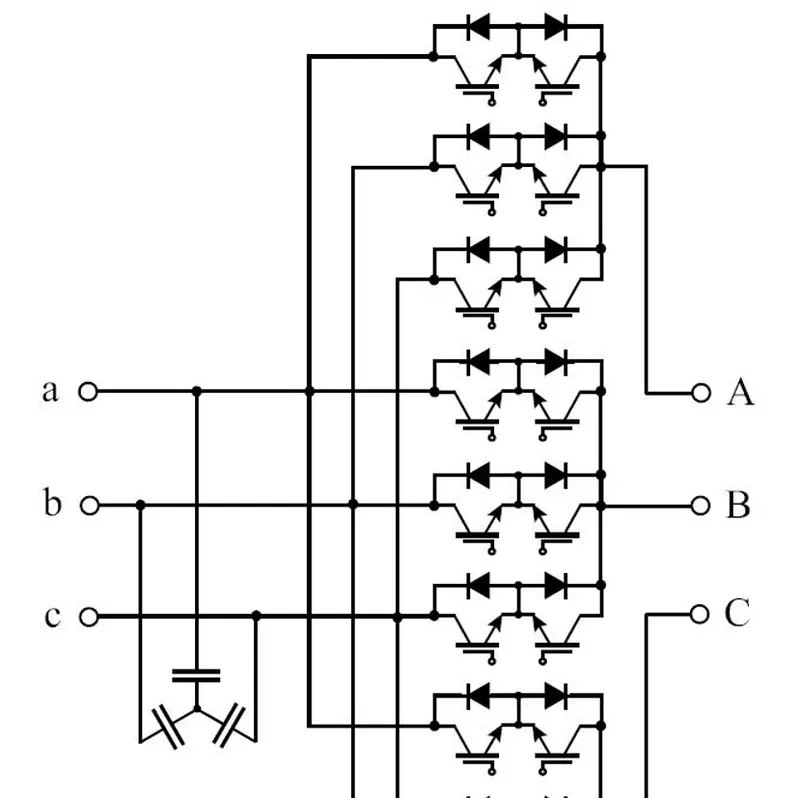
1. Which Types of power converter circuits are employed in electric and hybrid electric vehicles?
Type of Power converter:
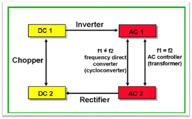
- EV Charger AC - DC converter:-
A rectifier is an electrical component that converts alternating current (AC) to direct current (DC). A rectifier is analogous to a one-way valve that allows an electrical current to flow in only one direction. The process of converting AC current to DC current is known as rectification. A rectifier can take several physical forms, such as solid-state diodes, vacuum tube diodes, mercury-arc valves, silicon-controlled rectifiers, and various other silicon-based semiconductor switches.
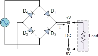
Power Diodes can be connected together to form a full wave rectifier that converts AC voltage into pulsating DC voltage for use in power supplies
Motor Drive DC - AC Inverter:-
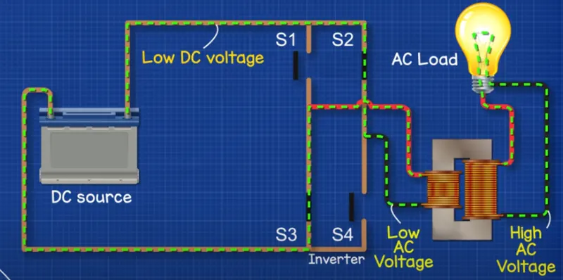
Broadly speaking, an inverter is an electrical device that converts electricity derived from a DC (Direct Current) source to AC (Alternating Current) of the type that can be used to drive a device or appliance. In a solar power system, for example, the power stored by batteries charged by solar panels is converted to standard AC power by the inverter which provides the power to plug-in outlets and other standard devices.
- DC-DC CHOPPER:
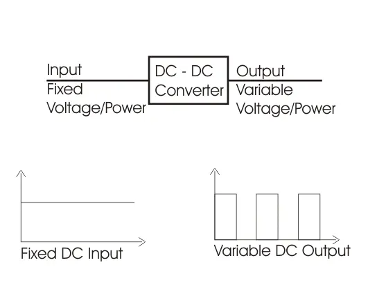
DC to DC Converters. These converters can converter a fixed DC input
voltage into variable DC voltage or vice versa. The DC output voltage is
controlled by varying duty cycles.
- step-up converter(12v to 100v)
- step-down converter(100v to 12v)
AC -AC CONVERTER:
AC to AC Converters. These converters can convert from a fixed ac
input voltage into a variable AC output voltage. The output voltage is
controlled by varying the firing angles of TRIAC. These types of converters are
known as AC voltage regulators.
2. An Electric Vehicle's powertrain with a 72V battery pack is shown in the diagram below. The duty ratio for the acceleration operation is 'd1' and for the braking operation the duty ratio is 'd2'.
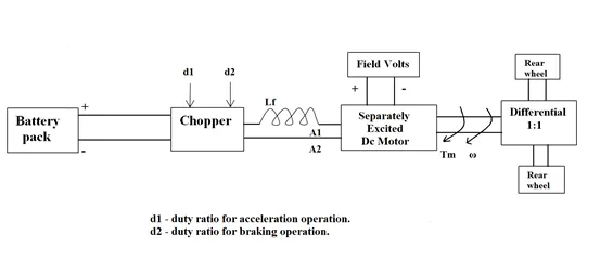
The other parameters of the electric vehicle are given below,
Motor and Controller Parameters:
Rated Armature voltage= 72 V
Rated armature current= 400 A
Ra= 0.5Ω, KΦ= 0.7 Volt second
Chopper Switching frequency= 400 Hz
The vehicle speed-torque characteristics are given by the below equation

What is EV steady state speed if the duty cycle is 70%?
the angular velocity ω">ωω of DC motor I was given by
w = V _ T.R
K0 K0^2
So T = v.k0 - w.k0^2
R R
Now putting all the values in the above equation
Since the duty cycle is 70%, V = 72*0.7 = 50.4V
T = 54.04 * 0.7 - w.0.7^2
0.5 0.5
Tm = 70.56 – 0.98w
At a steady state,
Tv = Tm
On equating both sides we get,
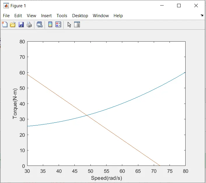
ω=38.90rad/s">w=38.90rad/s
`V steady state speed if the duty cycle is 70% is 38.90 rad/s`
MATLAB program for speed torque characteristics.
To calculate Angular Speed Value (rad/s)
Assuming Parameters -
V = 50.4 V
KΦ = 0.7-volt second
Ra = 0.5 ohm
T = 33.09 Nm
Simulink Model -
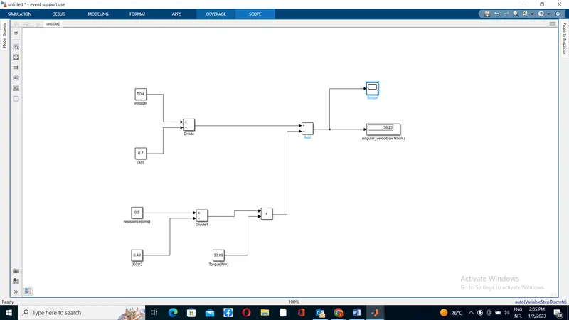
Conclusion - The value of Angular Speed comes out to be 38.23 rad/sec.
4. Refer to the blog below topic:
Induction Versus DC brushless motors by Wally Rippel, Tesla
Explain in brief the author’s perspective.
- He was an Engineer at AeroVironment. he help develop Ev vehicles and made his own Electrical vehicle.
- The author showed more interest in electric vehicles and hybrid electric vehicles.
- He mentioned the difference between 3 phase Induction motor and DC brushless motor.
- A 3-phase induction motor is connected to utility type 3-phase power, torque is produced at the outset; the motor has the ability to start under load. No inverter is needed. (Were an inverter needed, Tesla’s invention would have been useless until sometime in the 1960s.) The fact that induction motors are directly compatible with conventional utility power is the main reason for their success. In contrast, a brushless DC motor produces no starting torque when directly connected to fixed-frequency utility power. They really need the aid of an inverter whose “phase” is maintained in step with the angular position of the rotor.
- The advantages of a brushless motor over brushed motors are a high power-to-weight ratio, high speed, electronic control, and low maintenance. Brushless motors find applications in such places as computer peripherals (disk drives, printers), hand-held power tools, and vehicles ranging from model aircraft to automobiles. In modern washing machines, brushless DC motors have allowed the replacement of rubber belts and gearboxes with a much simpler and more reliable direct-drive design.
CONCLUSION -
- The author differentiates the EV and HEV also the types of converters used in the modern Vehicle.
- DC brushless drivers will likely continue to dominate in the hybrid and coming plug-in hybrid market
- The author also discusses the best possible option available in the market.