Week-7 Challenge: DC Motor Control
A. Explain a MATLAB demo model named ‘Speed control of a DC motor using BJT H-bridge’.
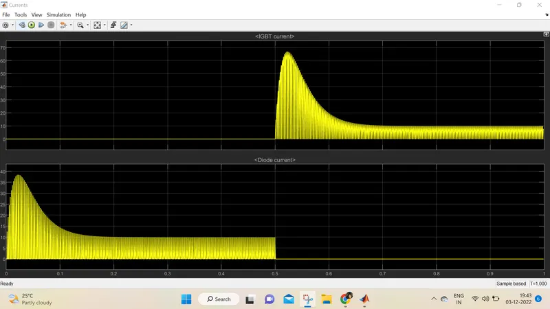
B. Comment on the armature current shoot-up from the scope results.
C. Refer to the help section of ‘The Four-Quadrant Chopper DC Drive (DC7) block’. Compare it with the H-bridge model.
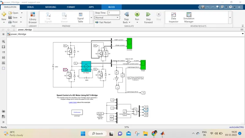
In this demo , H bridge is used to generate chopped voltage ,thereby controlling speed of DC motor.
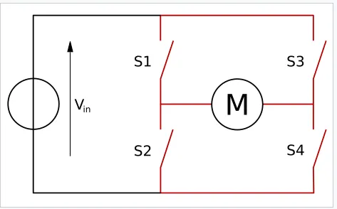 This is fundamental structure of H bridge
Four IGBT switches with freewheeling diodes are utilized in the construction of this model. The IGBTs have a forward voltage drop Vf of 1 volt while diodes have a forward voltage of 0.8 volts.
During the operation, two pairs of IGBTs are switched simultaneously by the control circuitry having the sequence as follows Q1 &Q4 or Q2 & Q3.
To supply the positive voltages to the DC motor to rotate it in the forward direction, Q1 and Q4 are supplied with the firing angles, and D2 & D3work as a freewheeling diode during the operation.
Moreover, to supply the negative supply voltages to the DC motor to rotate it in the reverse direction, Q2 and Q3 are supplied with the firing angles, and D1 & D4
act as a freewheeling diode.
Control circuitry for switches
The IGBTs require a control gate signal to operate hence the gate is operated by providing a Simulink signal (1/0).
The gate is turned on when 1 is applied while it is off when 0 is applied. The variation in the duty cycle results in variation in the rpm of the DC motor.
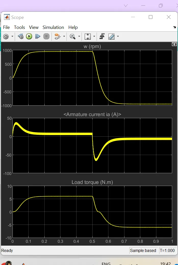
Speed of motor:
- Initially increases to 0 to nearly 900 rpm upto 0.5 secs(Forward motoring action takes place).
- Then speed reduces to 0 rpm(Forward dynamic breaking action takes place).
- Then speed increases from 0 to -900 rpm at upto 1 sec( Reverse motoring action takes place).
- Then reverse dynasmic breaking occurs(Not shown in scope).
Load torque of motor:
- Initially torque increase from 0 to 0.5 secs in forward motoring action.
- Then torque reduces to 0 Nm in forward dynamic breaking mode.
- Then torque increases in reverse direction in reverse motoring action upto 1 sec.
- Again torque reduce to zero.
B) Armature current shoot up in motor.
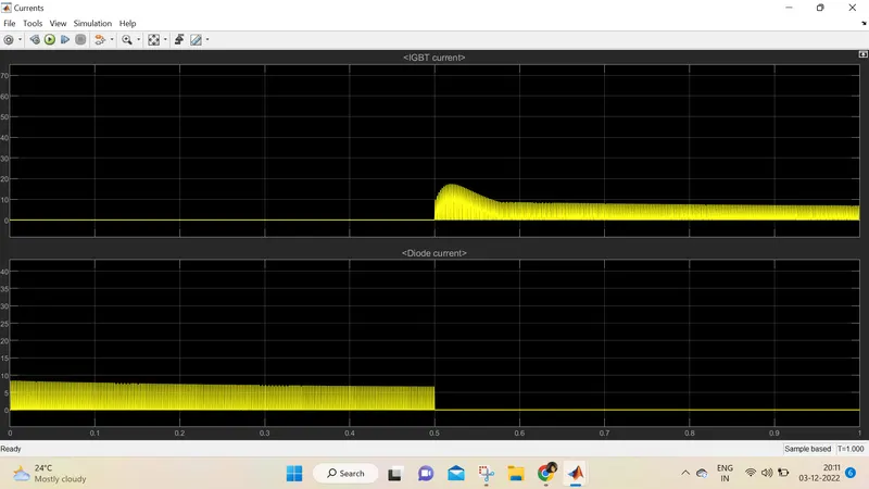
Here the initial current shoot up is due to sudden increase in voltage which inurns regulated by duty cycle.In this case motor driven in 75% of duty cycle.(i.e) 0.75*240= 180 V.
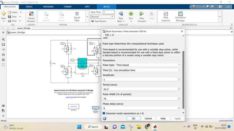
We can change the duty cycle to 50%(120 V) and seen the results as,
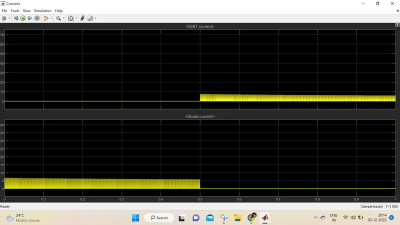
furthur reduction in duty cycle to 40%, current spike reduces tremendously.
C:
COMPARISON OF 4 QUADRANT CHOPPER AND BJT H BRIDGE:
1) the 4 quadrant chopper works in all four modes like
- forward motoring
- forward breaking
- reverse motoring
- reverse breaking
but the BJT h bridge model works on only two modes
- forward motoring
- reverse motoring
2)to change the direction of rotation of motor from forward to reverse and vice versa , the current signals get transited from one to other switch while in h bridge model, the direction of rotation of motor is changed by changing the polarity of current.
3)the 4 quadrant chopper have high switching frequency
while h bridge model have low switching frequency
4)the armature current in 4 quadrant chopper have a little spike at transition from one to other switch because of high swithing frequency while h bridge model have high spike of current.
5) the 4 quadrant chopper is generally used in industrial application while h bridge model is used in robotics.
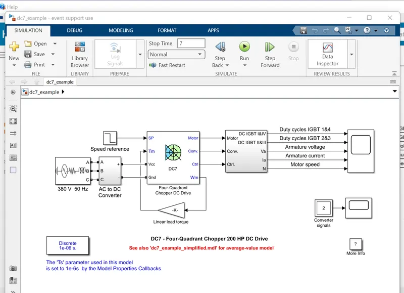
The first regulator is a speed regulator, followed by a current regulator. The speed regulator outputs the armature current reference (in p.u.) used by the current controller in order to obtain the electromagnetic torque needed to reach the desired speed. The speed reference change rate follows acceleration and deceleration ramps in order to avoid sudden reference changes that could cause armature over-current and destabilize the system. The current regulator controls the armature current by computing the appropriate duty ratios of the 5 kHz pulses of the four IGBT devices (Pulse Width Modulation). For proper system behaviour, the instantaneous pulse values of IGBT devices 1 and 4 are opposite to those of IGBT devices 2 and 3. This generates the average armature voltage needed to obtain the desired armature current. In order to limit the amplitude of the current oscillations, a smoothing inductance is placed in series with the armature circuit.
The main advantage of this drive, compared with other DC drives, is that it can operate in all four quadrants (forward motoring, reverse regeneration, reverse motoring, and forward regeneration). In addition, due to the use of high switching frequency DC-DC converters, a lower armature current ripple (compared with thyristor-based DC drives) is obtained. However, four switching devices are required, which increases thecomplexity of the drive system.
First Quadrant Operation:
For first quadrant operation, CH4 is kept ON, CH3 is kept OFF and CH1 is operated. When both CH1 & CH4 are ON simultaneously, the load gets directly connected to the source and hence the output voltage becomes equal to the source voltage. This essentially means that vo = vs. It may be noted that the load current flows from source to load as shown by the direction of io.
When CH1 is switched OFF, the load current free wheels through CH4 and D2. During this period, the load voltage and current remains positive.
Thus, both the output voltage vs and load current io are positive and hence, the operation of chopper is in first quadrant. It may be noted that, Class-E chopper operates as a step-down chopper in this case.
Second Quadrant Operation:
To obtain second quadrant operation, CH2 is operated while keeping the CH1, CH3 & CH4 OFF. When CH2 is ON, the DC source in the load drives current through CH2, D4, E and L. Inductor L stores energy during the On period of CH2.
When CH2 is turned OFF, current is fed back to the source through D1, D4. It should be noted at this point that (E+Ldi/dt) is more than the source voltage Vs. As load voltage Vo is positive and Io is negative, it is second quadrant operation of chopper. Since, the current is fed back to the source, this simply means that load is transferring power to the source. Kindly read step up chopper for detailed analysis and better understanding.
For second quadrant operation, load must contain emf E as shown in the circuit diagram. In second quadrant, configuration operates as a step-up chopper.
Third Quadrant Operation:
To obtain third quadrant operation, both the load voltage and load current should be negative. The current and voltage are assumed positive if their direction matches with what shown in the circuit diagram. If the direction is opposite to what shown in the circuit diagram, it is considered negative. One important thing to notice is that the polarity of emf E in load must be reversed to have third quadrant operation. Circuit diagram of Class-E chopper for third quadrant operation is shown below.
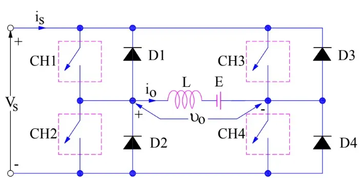
For third quadrant operation, CH1 is kept off, CH2 is kept ON and CH3 is operated. When CH3 is ON, load gets connected to source and hence load voltage is equal to source voltage. But carefully observe that the polarity of load voltage vo is opposite to what shown in the circuit diagram. Hence, vo is assumed negative. Let us now see what is the status of load current io. It may be seen that io is flowing in the direction opposite to shown in the circuit diagram and hence negative.
Now, when CH3 is turned OFF, the negative load current free wheels through the CH2 and D4. In this manner, vo and io both are negative. Hence, the chopper operates in third quadrant.
Fourth Quadrant Operation:
To obtain fourth quadrant operation, CH4 is operated while keeping CH1, CH2 and CH3 OFF. The polarity of load emf E needs to be reversed in this case too like third quadrant operation.
When CH4 is turned ON, positive current flows through CH4, D2, L and E. Inductance L stores energy during the time CH4 is ON. When CH4 is made OFF, current is fed back to the source through diodes D2, D3. Here load voltage is negative but the load current is always positive. This leads to chopper operation in fourth quadrant. Here, power is fed back to the source from load and chopper acts as a step-up chopper.
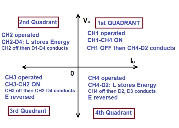
The operation of a four quadrant chopper or Class-E chopper is summarized in the figure below.
Que 2:Develop a 2-quadrant chopper using simulink & explain the working of the same with the relevant results. (Refer to article - Multiquadrant operation of motor )
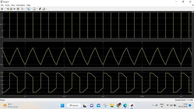
Class-C or Type-C Chopper is a category of chopper which can operate in first as well as second quadrant. This basically means that, the power can either flow from source to load or load to source in this chopper. This kind of chopper is also known as Two Quadrant Class-A chopper.
Operation / Working of Class-C or Type-C Chopper:
As we know that, a Class-A and Class-B chopper operates in first and second quadrant respectively. Therefore, if we connect both these types of chopper in parallel then it is possible to have chopper operation in first as well as second quadrant.
In fact, Class-C or Type-C chopper is obtained by the parallel connection of Class-A and Class-B chopper. Figure below shows the circuit diagram of this type of chopper.
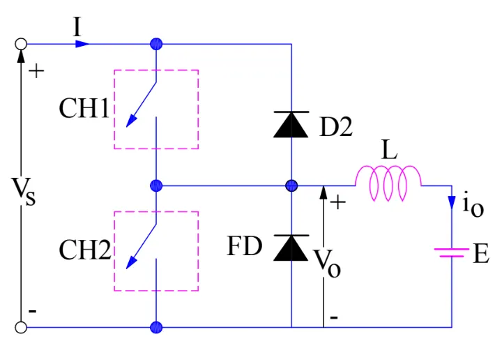
In the circuit diagram chopper CH1, free-wheeling diode (FD) and load are forming Class-A Chopper whereas chopper CH2, D2 and Load are forming Class-B chopper. Both these choppers are connected in parallel. To obtain first quadrant operation we should switch ON chopper CH1 and for getting second quadrant operation we should switch ON chopper CH2. Let us discuss this in detail.
Case-1: When CH1 is switched ON / OFF:
When chopper CH1 is switched ON, source Vs directly gets connected to the load and hence, load voltage Vo is equal to source voltage. The direction of load current is from source to load as shown in the circuit diagram which is assumed positive.
When CH1 is switched OFF, the free-wheeling diode FD comes into the circuit as it gets forward biased and hence shorts the load. Therefore, the output voltage Vo becomes zero. However, the io continues to die down through the FD and L in the same direction as shown in circuit diagram. Thus, the average output voltage Vo and current Io are positive and hence operation of chopper is in first quadrant. In fact, this is the Class-B mode of operation.
Case-2: When CH2 is switched ON / OFF
When chopper CH2 is switched ON, load DC source E drives current through CH2 and load. The direction of this current io will be opposite to that shown in circuit diagram and hence is assumed negative. Output voltage Vo is zero during this time. When CH2 is made OFF, diode D2 gets forward biased and hence the current into the source from the load. The output voltage is Vs in this time as the load is connected to the source through D2 during OFF time of chopper CH2. Thus, the load current is always negative i.e. operation of chopper is within second quadrant. In fact, this is the Class-B mode of operation.
rom the above two cases, we can conclude the following points:
- The output voltage Vo is zero when chopper CH2 is ON or free-wheeling diode FD conducts.
- The output voltage Vo is equal to source voltage Vs when chopper CH1 is ON or diode D2 conducts.
- The load current flows in the direction shown in circuit diagram i.e.io is positive when CH1 is ON or FD conducts.
- The load current flows opposite to the direction shown in circuit diagram i.e.io is negative when CH2 is ON or D2 conducts.
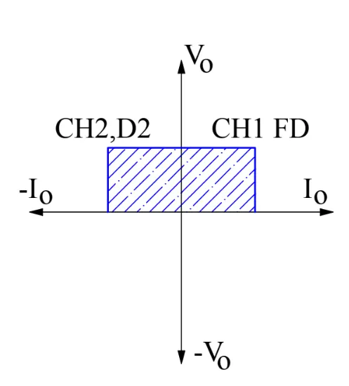
The average load voltage is always positive but the average load current may be positive or negative. Therefore, power flow may be from source to load (first quadrant operation) or load to source (second quadrant operation). The operating region of Class-C or Type-C chopper is shown below by hatched area.
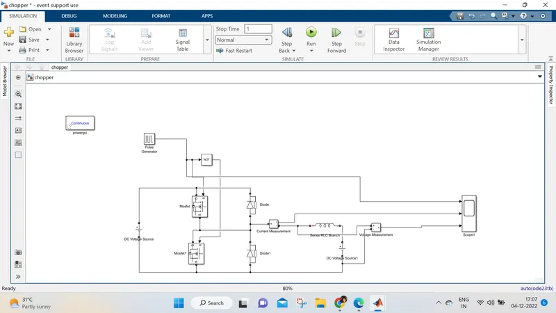
Blocks use for the model
- Power GUI
- Voltage measurement Block
- Current measurement block
- DC voltage source
- MOSFET
- Pulse generator
- Diode
- Series RLC band
- Logical Operator
3.BRUSHLESS DC MOTOR
A brushless DC motor (also known as a BLDC motor or BL motor) is an electronically commuted DC motor which does not have brushes. The controller provides pulses of current to the motor windings which control the speed and torque of the synchronous motor.
These types of motors are highly efficient in producing a large amount of torque over a vast speed range. In brushless motors, permanent magnets rotate around a fixed armature and overcome the problem of connecting current to the armature. Commutation with electronics has a large scope of capabilities and flexibility. They are known for smooth operation and holding torque when stationary.
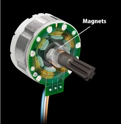
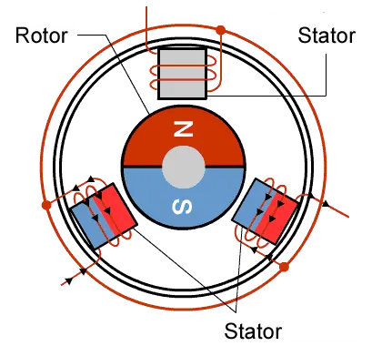
rushless DC motor has only two basic parts: rotor and the stator. The rotor is the rotating part and has rotor magnets whereas stator is the stationary part and contains stator windings. In BLDC permanent magnets are attached in the rotor and move the electromagnets to the stator. The high power transistors are used to activate electromagnets for the shaft turns. The controller performs power distribution by using a solid-state circuit.
Construction of Brushless DC motor
In this motor, the permanent magnets attach to the rotor. The current-carrying conductors or armature windings are located on the stator. They use electrical commutation to convert electrical energy into mechanical energy.
The main design difference between a brushed and brushless motors is the replacement of mechanical commutator with an electric switch circuit. A BLDC Motor is a type of synchronous motor in the sense that the magnetic field generated by the stator and the rotor revolve at the same frequency.
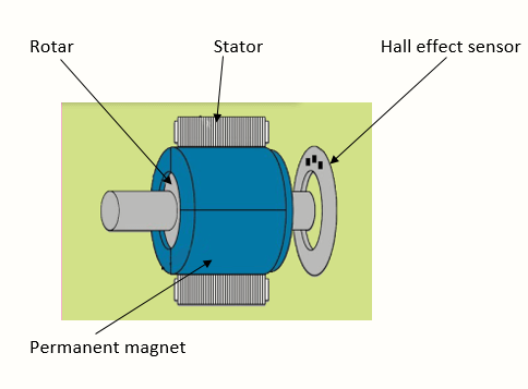
Brushless motor does not have any current carrying commutators. The field inside a brushless motor is switched through an amplifier which is triggered by the commutating device like an optical encoder.
The layout of a DC brushless motor can vary depending on whether it is in “Out runner” style or “Inrunner” style.
-
Outrunner – The field magnet is a drum rotor which rotates around the stator. This style is preferred for applications that require high torque and where high rpm isn’t a requirement.
-
In runner – The stator is a fixed drum in which the field magnet rotates. This motor is known for producing less torque than the out runner style, but is capable of spinning at very high rpm.
-
Working Principle of Brushless DC motor
BLDC motor works on the principle similar to that of a Brushed DC motor. The Lorentz force law which states that whenever a current carrying conductor placed in a magnetic field it experiences a force. As a consequence of reaction force, the magnet will experience an equal and opposite force. In the BLDC motor, the current carrying conductor is stationary and the permanent magnet is moving.
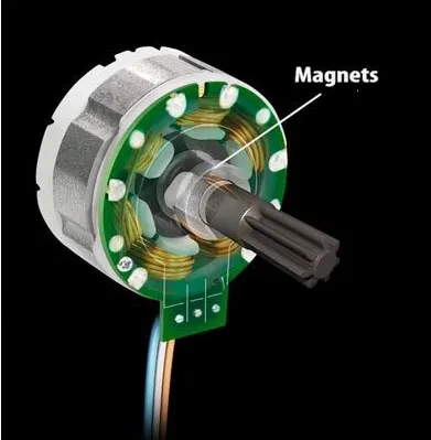
When the stator coils get a supply from source, it becomes electromagnet and starts producing the uniform field in the air gap. Though the source of supply is DC, switching makes to generate an AC voltage waveform with trapezoidal shape. Due to the force of interaction between electromagnet stator and permanent magnet rotor, the rotor continues to rotate.
With the switching of windings as High and Low signals, corresponding winding energized as North and South poles. The permanent magnet rotor with North and South poles align with stator poles which causes the motor to rotate.
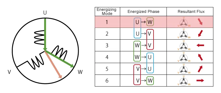
The current moves from U to W makes magnetizing the coils attracts the rotor consisting of permanent magnet makes moment as shown above to align with the resultant arrow(larger arrow).
North pole of magnet towards arrow mark of resultant arrow.
Rotation is maintained by continually switching the flux so that the permanent magnet is constantly chasing the rotating magnetic field induced by the coils. In other words, energizing of U, V, and W must be
continually switched so that the resultant flux keeps moving, producing a rotating field that continually pulls on the rotor magnet.
The advantages of a BLDC motor are:
- Brushless motors are more efficient as its velocity is determined by the frequency at which current is supplied, not the voltage
- As brushes are absent, the mechanical energy loss due to friction is less which enhanced efficiency.
- BLDC motor can operate at high-speed under any condition.
- There is no sparking and much less noise during operation.
- More electromagnets could be used on the stator for more precise control.
- BLDC motors accelerate and decelerate easily as they are having low rotor inertia.
- It is high performance motor that provides large torque per cubic inch over a vast sped rang.
- BLDC motors do not have brushes which make it more reliable, high life expectancies, and maintenance free operation.
- There is no ionizing sparks from the commutator, and electromagnetic interference is also get reduced.
- Such motors cooled by conduction and no air flow are required for inside cooling.
The disadvantages of a BLDC motor are:
- BLDC motor cost more than a brushed DC motor.
- The limited high power could be supplied to BLDC motor, otherwise, too much heat weakens the magnets and the insulation of winding may get damaged.