Week-6 Challenge: EV Drivetrain
Which types of power converter circuits are employed in electric and hybrid electric vehicle?
Power electronic converters are used everywhere in normal daily routines at home, commercial workplaces or in an industrial environment.
Power electronics is an enabling technology for the development of these environmentally friendlier vehicles and implementing the advanced electrical architectures to meet the demands for increased electric loads.
Due to the high power handling with higher efficiencies, these converters become an integral part of industrial electric drives, high electric power supplies, electric traction systems and automobile control equipments.
Power electronic converters perform various basic power conversion functions. This converter is a single power conversion stage that can perform any of the functions in AC and DC power conversion systems.
Hence it becomes integral part of EV, as power conversion is smooth lossless and efficient .
There are different types of power electronic converters used for performing different functions (such as inversion, rectification, etc.) which are rated from a few milliwatts to a few thousand watts.
Depending on the type of function performed, power electronic converters are categorized into following types.
- AC to DC = Rectifier: It converts AC to unipolar (DC) current
- DC to AC = Inverter: It converts DC to AC of desired frequency and voltage
- DC to DC = Chopper: It converts constant to variable DC or variable DC to constant DC
- AC to AC = Cycloconverter, Matrix converter: It converts AC of desired frequency and/or desired voltage magnitude from a line AC supply.
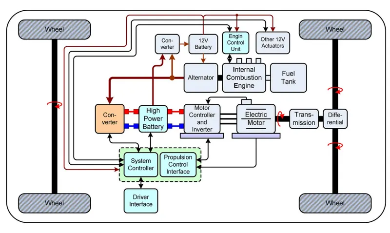
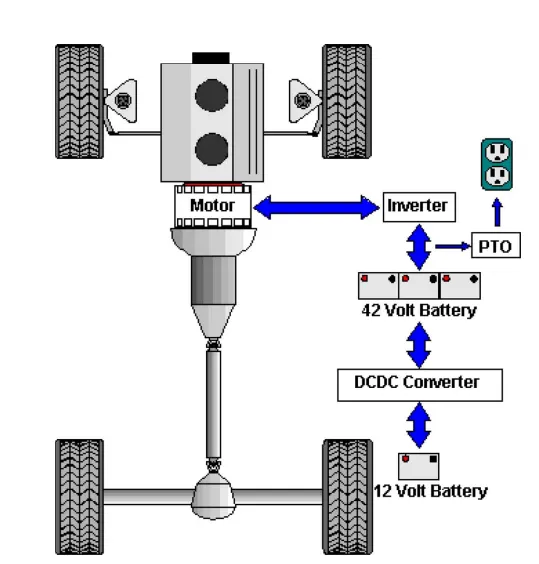
reference :"IEEE TRANSACTIONS ON INDUSTRIAL ELECTRONICS, VOL. 55, NO. 6, JUNE 2008"
QUE 2: An Electric Vehicle's powertrain with 72V battery pack in shown in the diagram below. The duty ratio for acceleration operation is 'd1' and for the braking operation the duty ratio is 'd2'.
The other parameters of the electric vehicle is given below,
Motor and Controller Parameters:
Rated Armature voltage= 72 V
Rated armature current= 400 A
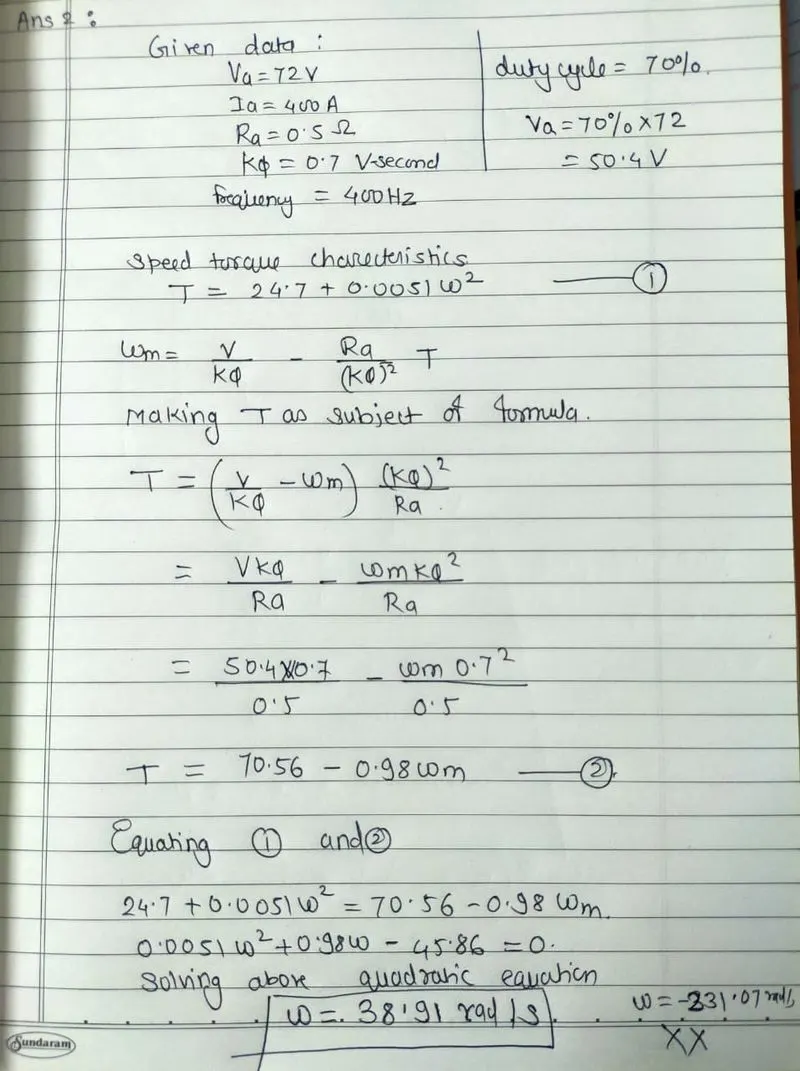
Ra= 0.5Ω, KΦ= 0.7 Volt second
Chopper Switching frequency= 400 Hz
The vehicle speed-torque characteristics are given by the below equation

What is EV steady state speed if duty cycle is 70%?
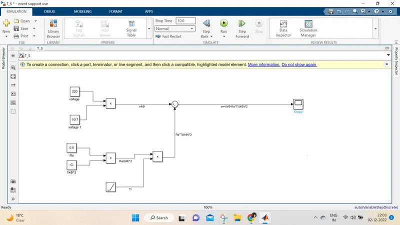
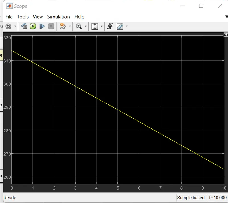
Que 3:Develop a mathematical model of a DC Motor for the below equation using Simulink.
ω= V/Kϕ -Ra/Kϕ^2 .T
Que 4:Refer to the blog on below topic:
Induction Versus DC brushless motors by Wally Rippel, Tesla
Explain in brief about author’s perspective.
About Author:
Wally E. Rippel is a long-time developer and advocate of battery electric vehicles.
In 1968, as an undergraduate student, he built the Caltech electric car (a converted 1958 VW microbus) and won the Great Transcontinental Electric Car Race against MIT.
In the 1970s and 1980s, Rippel worked for the Jet Propulsion Laboratory on electric vehicle battery research, among other things.
Around 1990, Rippel joined AeroVironment and helped to design the GM Impact, later named the EV1; he had worked on the induction motor for the car before joining AeroVironment. In 2003, he was one of the participants in the mock funeral for the EV1 as GM prepared to collect the last few for crushing.
Rippel left AeroVironment in 2006 and joined Tesla Motors, where he continued his lifelong work on the battery electric car. He left Tesla in 2008.
According to Rippel, in this continuously evolving world, we can not consider any engines or machines as best .
The choice of Engines depends upon condition where we are driving the vehicle.
If we only concentrate on performance and efficiency then it would be costly or vice a versa .
Rippel then give the example that ,previously use of lead acid batteries, DC brush motors is very common ,which we do not use now so frequently.
According to him ,Induction Machines and Brushless DC M achines are here for long years .
Rippel gives close insight of DC brushless motor and Induction motor
DC brushless machine that rotor generate the magnetic field with two or more permanent magnet and this magnetic field enters the stator core (a core made up of thin, stacked laminations) and interacts with currents flowing within the windings to produce a torque interaction between the rotor and stator. As the rotor rotates, it is necessary that the magnitude and polarity of the stator currents be continuously varied. But without inverter its of no use
Induction Motor has no magnet it contains steel laminations with buried peripheral conductors .He describe working of induction motor that Currents flowing in the stator windings produce a rotating magnetic field that enters the rotor. In turn, the frequency of this magnetic field as “seen” by the rotor is equal to the difference between the applied electrical frequency and the rotational “frequency” of the rotor itself. Accordingly, an induced voltage exists across the shorted structure that is proportionate to this speed difference between the rotor and electrical frequency. In response to this voltage, currents are produced within the rotor conductors that are approximately
proportionate to the voltage, hence the speed difference. Finally, these currents interact with the original magnetic field to produce forces ie. rotor torque.
He concluded that both Machines has their pros and cons and one has to select the motor by optimization techniques