Week-7 Challenge: DC Motor Control
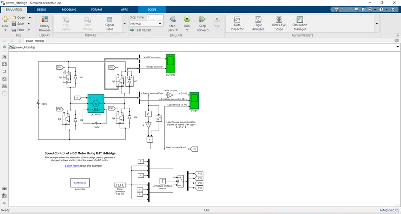
1. A. Explain a MATLAB demo model named ‘Speed control of a DC motor using BJT H-bridge’.
ANS;
BJT:A bipolar junction transistor is Amplify or magnify the signal and have 2 p-n junction with 3 terminal semoconductor device. It is a current controlled device. The three terminals of the BJT are the base, the collector, and the emitter.
when BJT used for power switching applications, operates as an IGBT. When it is conducting (BJT operating in the saturated region), a forward voltage Vf is developed between collector and emitter (in the range of 1 V). Therefore, the IGBT block can be used to model the BJT device.
The IGBT block does not simulate the gate current controlling the BJT or IGBT. The switch is controlled by a Simulink® signal (1/0). The DC motor uses the preset model (5 HP 24V 1750 rpm). It simulates a fan type load (where Load torque is proportional to square of speed). The armature mean voltage can be varied from 0 to 240 V when the duty cycle (specified in the Pulse Generator block) is varied from 0 to 100%.
The H-bridge consists of four BJT/Diode pairs (BJT simulated by IGBT models). Two transistors are switched simultaneously: Q1 and Q4 or Q2 and Q3. When Q1 and Q4 are fired, a positive voltage is applied to the motor and diodes D2-D3 operate as free-wheeling diodes when Q1 and Q4 are switched off. When Q2 and Q3 are fired, a negative voltage is applied to the motor and diodes D1-D4 operate as free-wheeling diodes when Q2 and Q3 are switched off.
Simulation:
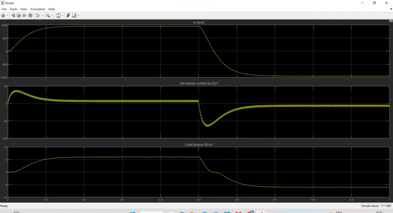
The motor starts in the positive direction with a duty cycle of 75% (mean DC voltage of 180V). At t= 0.5 sec., the armature voltage is suddenly reversed and the motor runs in the negative direction.
'Scope' shows motor speed, armature current and load torque and 'Currents' shows currents flowing in BJT Q3 and diode D3.
H-bridge DC chopper circuit is used to control the speed of the motor. and IGBT acts as BJT in power switching devices.
Four(Q1,Q2,Q3,Q4) IGBT switches are used for inverting the DC voltage 0 to 240 v supply.The current flows from collector(C) to emitter(E).
The gate are controlled by the pulses(P1,P2,P3,P4) according to the armature voltge of motor given by pulse generator.
at step Q1 and Q2 switches are on and for freewheeling D2,D3 diode are ON in this case we can achive the Forward motoring and forward breaking
in Second step,Q2 ,Q3 are closed by giving V ,current from battery passes through Q2 and Q3.Diode D1,D4 are used as free wheeling diode in this stateIn this case reverse motoring and reverse breaking are held.The current direction change its direction in this state. that DC voltage os feeded to the motor
and here taking the 0.5s is sampling time.and DC voltage is given to field winding is 300V
that is show in the fig below
after that run this simulation model the speed and torque graph have to analyzed
here is the speed an torque is given
from the speed wave
initially speed is increase from 0 to 900 rpm in the of 0.5s so Forward motoring is achived
after that it fall down to "0' so it is breaking action
and the same way torque also expected as same here
and again speed increase to 900 but in the nagatove diretion so it is Reverse motoring action
and fall down to 0 after some time reverse breaking mode.
B. Comment on the armature current shoot-up from the scope results.
from the above result initial current shoot up is due to sudden increase in voltage which inurns regulated by duty cycle. and after that Sudden shoot up canceled in starting condition but slight shootup after 0.5 sec in reverse motoring condition.
so it is relates to speed and torque also
C. Refer to the help section of ‘The Four-Quadrant Chopper DC Drive (DC7) block’. Compare it with the H-bridge
model.
after the refering four quadrant choopr
1.in DC7 chopper model speed controlled by varying current and in H-brige model speed controlled by varying duty cycles voltages.
2.In four quadrant DC chopper model smoothing inductance is used for smooth increase and decrease in current flow which inturns controlling the motor speed smoothly,while in H-bridge it is not present.
Here the operation is discreat and in H-bridge model it is continuous.
3.Hence 4 quadrant DC choppers are used mostly in electric vehicles.
2.Develop a 2-quadrant chopper using simulink & explain the working of the same with the relevant results.
ANS:
The DC motor is used in many industrial applications requiring variable speed and load characteristics due to its ease of control. A chopper drive-based speed control is widely preferred as far as speed control is concerned. Choppers are mostly applied in electric cars, conversion of wind and solar energy, and DC motor regulators. A chopper uses the high speed to connect and disconnect from a source load. A fixed DC voltage is applied intermittently to the source load by continuously triggering the power switch ON/OFF. The period for which the power switch stays ON or OFF is referred to as the chopper’s ON and OFF state times, respectively.
The four-quadrant chopper is a chopper which can operate in all the four quadrants. The power can flow either from source to load or load to source in this chopper. In the first quadrant, a Class-E chopper acts as a Step-down chopper whereas in the second quadrant it behaves as a Step-up chopper. This type of chopper is also known as a Class-E or Type-E chopper. This article describes the working principle and operation of a Class-E chopper with the help of a circuit diagram.
3. Explain in a brief about operation of BLDC motor.
ANS:
A motor converts supplied electrical energy into mechanical energy. Various types of motors are in common use. Among these, brushless DC motors (BLDC) feature high efficiency and excellent controllability, and are widely used in many applications. The BLDC motor has power-saving advantages relative to other motor types.
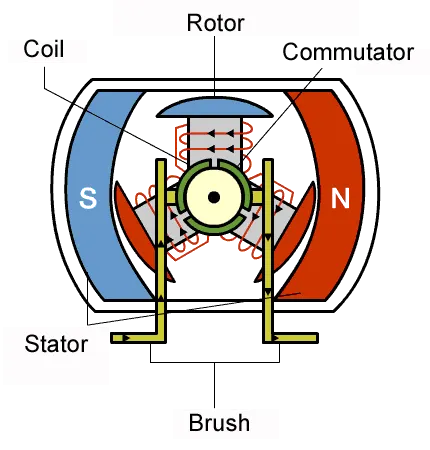
if we consider the simple brushed DC motor. In this type of motor, electrical current is passed through coils that are arranged within a fixed magnetic field. The current generates magnetic fields in the coils; this causes the coil assembly to rotate, as each coil is pushed away from the like pole and pulled toward the unlike pole of the fixed field.
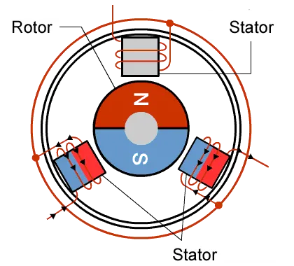
but in BLDC in the same way to provide feild flux permanent magnet is used to create rorating force
As their name implies, brushless DC motors do not use brushes. With brushed motors, the brushes deliver current through the commutator into the coils on the rotor. So how does a brushless motor pass current to the rotor coils? It doesn’t—because the coils are not located on the rotor. Instead, the rotor is a permanent magnet; the coils do not rotate, but are instead fixed in place on the stator. Because the coils do not move, there is no need for brushes and a commutator.
With the brushed motor, rotation is achieved by controlling the magnetic fields generated by the coils on the rotor, while the magnetic field generated by the stationary magnets remains fixed. To change the rotation speed, you change the voltage for the coils. With a BLDC motor, it is the permanent magnet that rotates; rotation is achieved by changing the direction of the magnetic fields generated by the surrounding stationary coils. To control the rotation, you adjust the magnitude and direction of the current into these coils.
advantages:1. it have more efficiency
2.easy to control the speed of BLDC
3.low noice