Week-7 Challenge: DC Motor Control
1.
A.
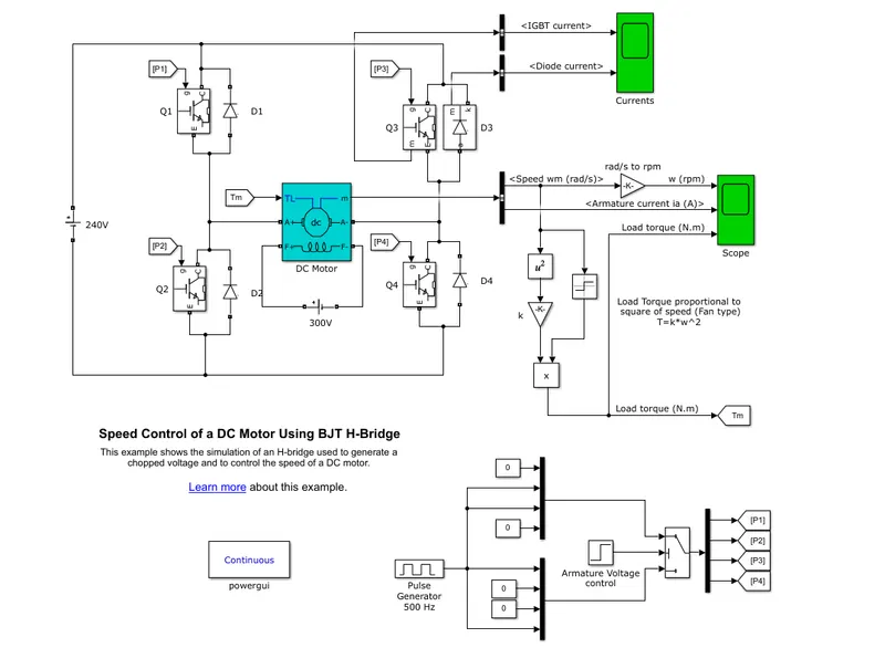
- When used for power-switching applications, the Bipolar Junction Transistor (BJT) operates as an IGBT.
- When it is conducting (BJT operating in the saturated region), a forward voltage Vf is developed between the collector and emitter (in the range of 1 V). Therefore, the IGBT block can be used to model the BJT device.
- The IGBT block does not simulate the gate current controlling the BJT or IGBT. A pulse generator controls the switch. The DC motor uses the preset model (5 HP 24V 1750 rpm).
- It simulates a fan-type load (where load torque is proportional to the square of speed).
- The armature means voltage can be varied from 0 to 240 V when the duty cycle is varied from 0 to 100%.
- The H-bridge consists of four BJT/Diode pairs (BJT simulated by IGBT models).
- Two transistors are switched simultaneously: Q1 & Q4 or Q2 & Q3.
- When Q1 & Q4 are fired, a positive voltage is applied to the motor and diodes D2-D3 operate as free-wheeling diodes when Q1 & Q4 are switched off.
- When Q2 & Q3 are fired, a negative voltage is applied to the motor and diodes D1-D4 operate as free-wheeling diodes when Q2 & Q3 are switched off.
B.
- At 75% duty cycle, we can see that the current plot has initially a very high value and then becomes steady; it shows the same path in the negative direction.

- At 55% duty cycle, we can see that the current shoot-up decreases and then becomes steady. In the negative direction, it has initially a high value and then it becomes steady.

- At a 45% duty cycle, the current plot has an almost smooth current flow.

C.
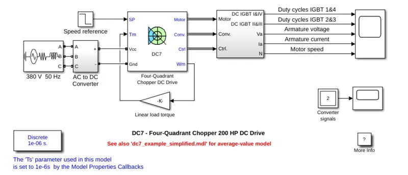
Comparison between Four-Quadrant Chopper DC Drive and H-bridge
| Four-Quadrant Chopper DC Drive | H-bridge |
| To change the motor direction, the polarity has to be changed. | To change the motor direction, the current signal has to be interrupted. |
| It can operate in all 4 modes: Forward motoring, forward braking, reverse motoring and reverse braking. | It can operate in two modes: Forward and Reverse. |
| It has broader torque and power output ranges. |
It uses a single pulse generator which gives little torque and power output range. |
| It can be achieved up to 400 V. | It can be achieved up to 350 V. |
| In this, the current has chopped values. | In this, the current has continuous values. |
| Regenerative braking is possible. | Regenerative braking is not possible. |
| Two PI regulator (speed regulator and current regulator) is used to obtain the electromagnetic torque needed to reach the desired speed & control the armature current and stabilize the system. | PI regulator is not used. |
| Four-quadrant chopper is an electronic switch that is used to interrupt one signal under the control of another. | H-bridge is an electronic circuit that switches the polarity of the voltage applied to the load. |
| It is used to refer to numerous types of electronic switching devices and circuits used in power control and signal applications. | It is often used in Robotics and other applications to allow DC motors to run forward and backwards. |
2.
- Two-quadrant chopper operation occurs in 2 modes: motoring and braking modes.
- The chopper permits a change in the polarity of terminal voltage keeping the direction of the current constant.
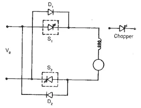
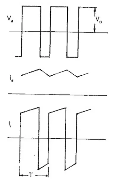
- In the figure, S1 & S2 are the choppers working as electronic switches and D1 & D2 are the feedback diodes.
- Assuming continuous conduction, both S1 & S2 operate simultaneously.
- When they are ON the load current Id increases, with the rate of rising depending upon the back emf and torque of the machine.
- When they are OFF, the load current is fed to the supply through diodes D1 & D2. The current decreases in this stage.
- From the figure, it is clear that the load voltage is effectively negative when the diodes conduct.
- The average value of the output voltage of the chopper
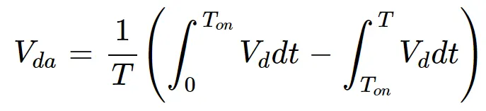

- Vda is zero for a = 0.5, the output voltage is an ac waveform with an average voltage equal to zero.
- For a > 0.5, the average value of the dc voltage is negative. The chopper works in the regeneration mode.
- The power flows from the load to the supply and the dc machine operates as a generator.
- For the control ratio of 0.5, the operation is similar to the inversion of a line commutated converter (α > 90).
- For a > 0.5, the chopper has the normal operation. The power flows from the supply to the load. This operation of the chopper is similar to the rectification of a line-commutated converter (α < 90).
- For a = 0.5, the load voltage is zero.
Simulink model:
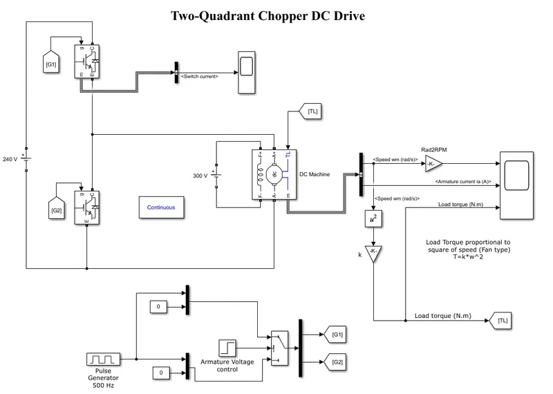
- When used for power-switching applications, the Bipolar Junction Transistor (BJT) operates as an IGBT.
- When it is conducting (BJT operating in the saturated region), a forward voltage Vf is developed between the collector and emitter (in the range of 1V). Therefore, the IGBT block can be used to model the BJT device.
- The IGBT block does not simulate the gate current controlling the BJT or IGBT.
- The PWM generator controls the switch. The DC motor uses the preset model (5HP 24V 1750rpm).
- It simulates a fan-type load (where Load torque is proportional to the square of speed).
- The armature mean voltage can be varied from 0 to 240 V when the duty cycle (specified in the Pulse Generator block) is varied from 0 to 100%.
- This model consists of two BJTs/Diodes connected parallel to the DC motor. When Q1 is fired, a positive voltage is applied to the motor and diode D2 operates as a free-wheeling diode when Q1 is switched OFF.
- When Q2 is fired, a negative voltage is applied to the motor and diode D1 operates as a free-wheeling diode when Q1 is switched OFF.
- The motor starts in the positive direction with a duty cycle of 75% (mean DC voltage of 180 V). At t = 0.5 sec., the armature voltage is suddenly reversed and the motor runs in the negative direction.
3.
-
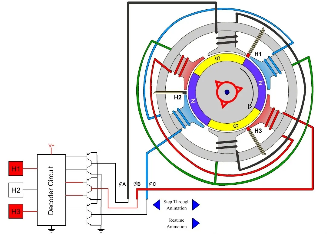
BLDC motor works on a principle of the Lorentz force which states that whenever a current-carrying conductor is placed in a magnetic field it experiences a force. As a consequence of reaction force, the magnet will experience an equal and opposite force.
-
In the BLDC motor, the current-carrying conductor is stationary and the permanent magnet is moving.
- When the stator coils get a supply from the source, it becomes an electromagnet and starts producing the uniform field in the air gap.
- Though the source of supply is DC, switching makes to generate an AC voltage waveform with a trapezoidal shape.
- Due to the force of interaction between the electromagnet stator and permanent magnet rotor, the rotor continues to rotate.
- With the switching of windings as High and Low signals, corresponding winding energized as North and South poles.
- The permanent magnet rotor with North and South poles aligns with the stator poles which causes the motor to rotate.