Week-7 Challenge: DC Motor Control
Answer 1) A. The Bipolar Junction Transistor(BJT) when used for power switching applications, operates as an IDBT. When it is conducting (BJT operating in the saturated region), a forward voltage Vf is developed between collector and emitter ( in the range of 1V). Therefore, the IGBT block can be used to model the BJT device.
The IGBT block does not simulate the gate current controlling the BJT or IGBT. The switch is controlled by a Simulink signal(1/0). The DC motor uses the preset model. It simulates a fan type load. the armature mean voltage can be varied form 0 to 240V When the duty cycle (specified in the Pulse Generator Block) is varied from 0 to 100%.
The H Bridge consists of four BJT/Diode paris ( BJT Simulated by IGBT models). Two transistor are switched siultaneously: Q1 and Q4 or Q2 and Q3. When Q1 and Q4 are fired, a positive voltage is applied to the motor and diodes D2-D3 opeate as free-wheeling diodes when Q1 and Q4 are switched off. When Q2 and Q3 are fired, a negative voltage is applied to the motor and diodes D1-D4 operated as free-wheeling diodes when Q2 and Q3 switched off.
The model below shows the ismulation of an H-Bridge used ot generate a chopped voltage and to control the speed of a DC motor.
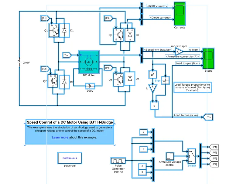
Here a block called puse generator is used to generate pulses of certain magnitude which are fed to this system constituting of four IGBT to create pulse width modulation.
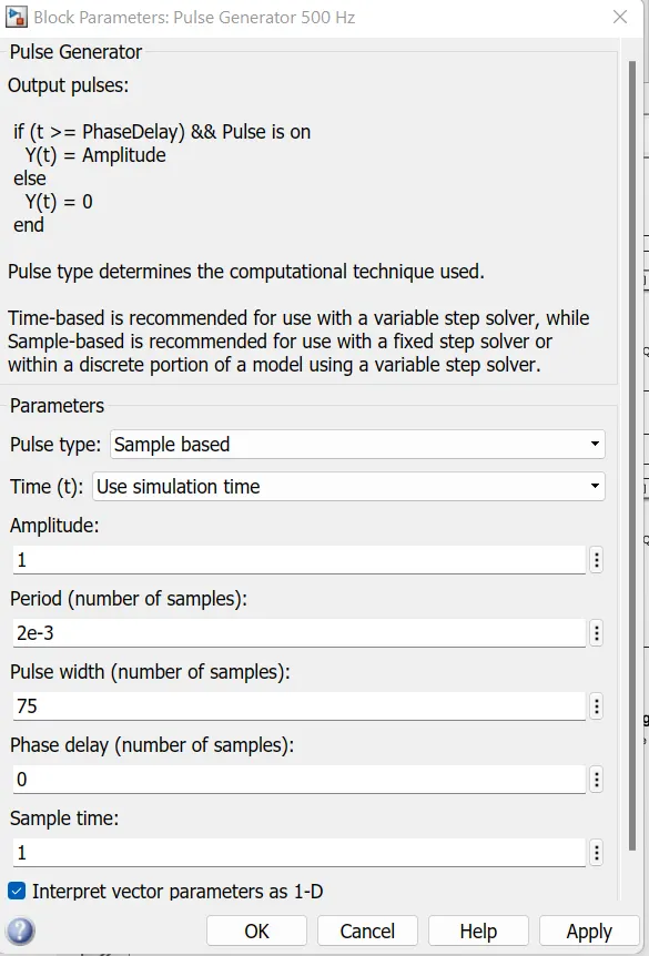
Case 1. In this case, we have taken the default paramters and the simulation is such that the motor starts rotating is positivedirection with the duty cycle of 75% with mean voltage of 180V. Scope shows the motor speed, armature current and load torque. Initially the block parameters for pulse generator are a follows.
Result- When we run the simulation for 1st case with keeping the parameters as default we get the gollowing result in scope.
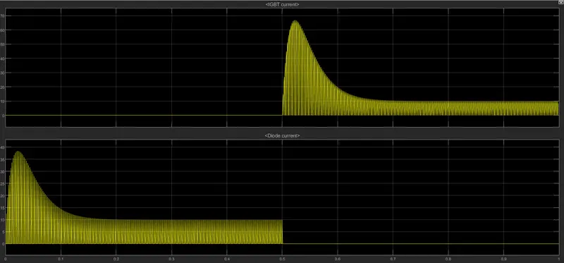
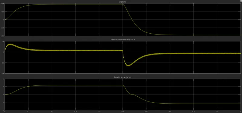
Here in the result aboe for the plot of current we can observe that at 0.5 sec., the armature voltage is suddenly reversed and the motor runs in the negative direction. So in the first half cycle, we can see that the motor attains a speed of 1000 RPM and a load torque of 6 Nm. Whereas, for the secodn half cycle the same values in the nagative direction. Here we can see that the armature current of DC motor does not shoot up.
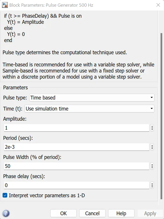
Case 2. In this case, the simulation is such that the motor starts rotating in positive direction with the duty cycle of 50% with mean voltage of 120 V. Scope shows the motor speed, armature current and load torque. The Block parameters for pulse generator for this case are as follows.
Result-When we run the simulation for 2nd case we get the following result in scope.
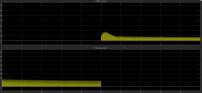
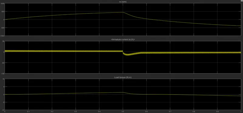
Here in the result above for the plot of current we can observe that at 0.5 sec. The armature voltage is suddenly reversed and the motor runs in the negative direction. so, for 50% duty cycle, in the first half cycle, we can see that motor speed reduced to approx 420 RPM and a load torque of 1.3 Nm respectively. Whereas, for the second half cycle the soame values in the negative direction. Here the armature current of DC motor not shoot up at 50%.
from the above observation we get to know that, as we reduce the pulse width(duty cycle), the motor speed and torque reduces and can attain zero wheras when we increase the value of pulse width gradually the speed of motor and torquee also increases gradually to its maximum value.
(C). The 200 HP DC motor is separately excited with a constant 140 V DC field voltage source. the armature voltage is provided by an IGBT converter contrlled by two PI regulatores. The converter is fed by a 515 V DC bus voltage during dynamic braking mode, a braking chopper has been added between the diode rectifier and the DC7 Block.
The first regulator is a speed, followed by a current regulator. The speed regulator outputs the armature current regerence (in p.u.) used by the current controller in order to obtain the electromagnetic trque needed to reach the desired speed. The speed regerence change rate follows acceleration and deceleration ramps in order to avoid obtain the electromagnetic torque needed ot reach the desired speed. the speed reference change rate follows acceleration and deceleration ramps in order to avoid sudden reference changes that could cause armature over-current by computing the appropriate duty ratios of the 5 KHz pulses of the four IGBT devices (pulse Width Modulation). For proper system behaviour, the instantaneous pulse values of IGBT devices 1 and 4 are opposite to those of IGBT Devcies 2 and 3. this generates the average armature voltage needed to obain the desired armature current. In ordert to limit the amplitude of the current oscillations, a smoothing inductance is placed in series with the armature circuit.
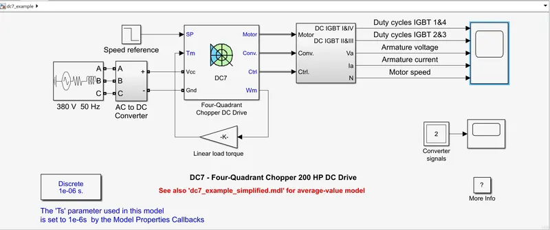
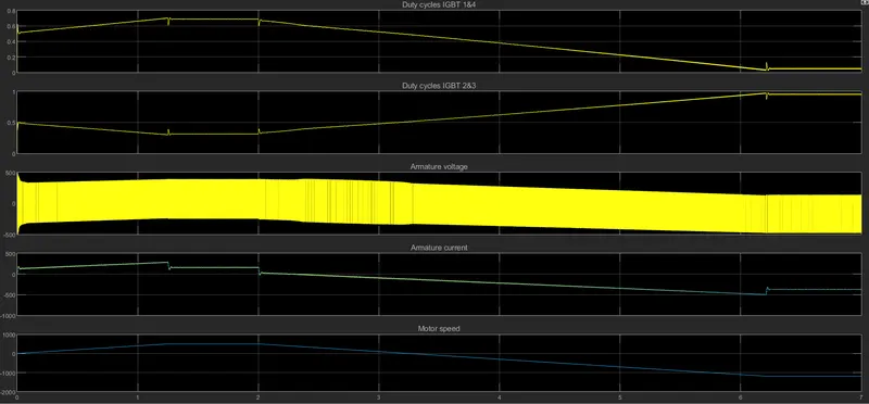
Before starting the simulation, set the intitial bus boltage to 515V via the GUI block (initial States Setting button and Cbus variable). Start the simulation. You can observe the motor armature voltage and current, the four IGBT pulses and the motor speed on the scope. The current and speed references are also shown. The motor is coupled to a linear load. Which means that the mechanical torque of the load is proportional to the sped. the speed reference is set at 500 rpm at t=0s. Obseve that the motor speed follows the refernce ram p accurately and reaches steady state arounmd t=13s. The armature current follows the current reference very well, with fast response time and small ripples. Notice that the current ripple frequency is 5kHz. At t=2s, speed reference drops to -1184 rpm. The current reference decreases to reduce the electromagnetic torque and causes the motor to deceleRATE With the help of the load torque(dynamic braking mode). This cause the DC bus voltage to increase. At t=3.25s, the motor reaches 0 rpm and the load torque reverses and becomes negative. The negative current now produces an accelerating electromagnetic torque to allow the motor to follow the negative spped ramp. At = 6.3s. the speed reaches -1184 rpm and stabilizes around its reference.
Result
Based on the above simulation perfomed we get the following result on the scope:
- The plot of duty cycles IGBT 1&4 are exactly opposite to that of duty cycles IGBT 2&3 as the pulse width of IGBT devices 1&4 are opposite to those of IGBT devices 2 &3.
- The desired armature current is obtained from the average armature voltage.
- The armature current follows the current reference very well, with fast respose time and smal ripples.
Comparison of Four Quadrant Chopper DC Drive (DC7) with BJT H bridge
- In four quadrant chopper DC drive model, the speed reference input is used to change the direction fo the motor rotation whereas in BJT H-Bridge model, The polarity is reversed across the terminals of the motor with respect to the battery, to change the dir tion of the motor rotation.
- In four quadrant chopper, the speed reference values is changed to control the speed of the motor whereas, in BJT H-bridge the speed of the motor is controlled by varying the with of the puse in pulse generator.
- The four quadrant chopper DC drive operates in four mode i.e Forward motoring, forward regenerative breaking, reverse motoring and reverse regenerative braking whereas, BJT H- bridge only operates in two modes, Forward and reverse.
- PI(proportional) controllers are used for speed and current control in DC7 and it is absent in BJT h-Bridge.
- The four quadrant chooper uses ramps to avoid current shoot up and smooth working and stability.
- The disturbances and current shoot up is low in DC7 wereas for BJT the shoot up is high because of switching losses.
- Due to the high switching frequency in the four quadrant chopper (DC-DC Converters), a low armature current is obtained.
- This why the overall performance and stability is good in Gour Quadrant Chopper DC drive as compared to BJT H-Bridge model.
- Only disadvantages is due to its complexity as it consist of four switching devices.
Answer 2) A DC to DC converter, also known as dc chopper, is a static device which is used to obtain a variable dc voltage from a constant dc votage source. Choppers are widely used in trolley cars, vattery- operated vehicles, traction motor control, control of large nubers of dc motors, etc, They are also used as dc voltage regulators. Choppers are of two types: (1) Step Down Choppers & (2) step up choppers. In step down choppers, the output voltage will be less than the input voltage, whereas in step up choppers output voltage will be more than the input voltage.
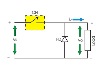
Chopper-Fed DC Motor Drive- DC motor is considered a SISO (Single Input and Single Output) system having torque speed characteristics compatible with most mechnanical loads. This make a DC motor controllable over a wide range of speeds by proper adjustment of the terminal voltage.
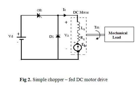
A simple chopper-fed DC motor drive in Fig 2. The basic principle ehind DC motor speed control is that the output speed of a DC motor can be veried by controlling armature voltage for speed below and up to rated speed keeping field voltage constant. The armature voltage can be controlled by controlling the duty cyctle of the converter.
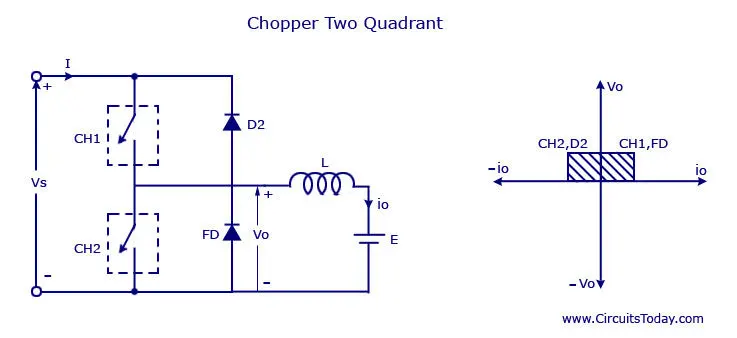
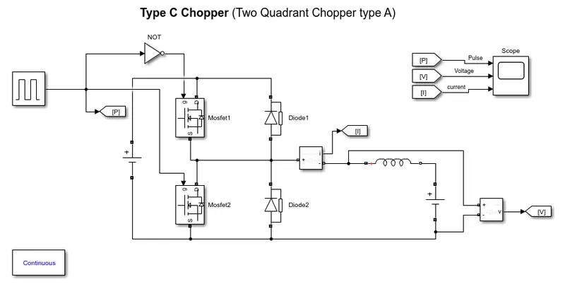
The above model is the model fo the Type Chopper. In this type of Chopper, the average voltage will be always positive byt the average load current might be positive or negative. The two switches CH1 and CH2 should not be turenc on simultaneoulsy as the combined action may cause a short circxuti in supply lines. For regenerative braking and motoring thses type of chopper configuration is used.
We will always get a positive output voltage V0 as the freewheeling diode FD is present across the load. When the Chopper CH1 is on the current flows from source to load. The inductor stores energy. When CH1 turn Off the freewheeling diode starts conducting and the output voltage v0 will be equal to Vs. The direction of the load current I0 The current I0 will be flowing towards the source. The load current will be negative when the CH2 is on. the current completes its path through diode D2
Answer 3) BLDC motor named as brushless DC motor having hight effecciency than other types of motors. This motor is also known to be synchronous motor.
Construction:
Most of the motor are having brushes in their rotor as it transfers current into the rotor circuit. But here differently rotor is placed with permanent magnet.
The stator coilis is wounded with coils, they are stationaly but producing variable DC voltages fro rotating the permanent magnet as changing the magnetic field of stator poles continuously.
The controlling of motor is by changing the magnitude and direction of current flowing through the stator windings.
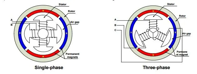
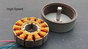
A BLDC motor with tree coils on the stator will have six electrical wires extending form thses coils. In most implementations three of htese wires will be connected internally, with the three.
Resmaining wires extending from the motor body. Wiring in the BLDC motor case is more complicated than simply connecting the power cell's positive and negative terminals. We will look more closely at how these motors work in the second session fo this series.
Operation of BLDC motor:
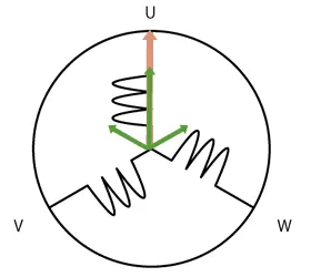
We can consider three winding terminal are comming out as U,V,W and their another ends are connected in single point as shown in below figure. The angle shift between two coils makes 120 degree.
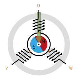
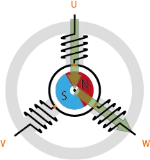
The current moves from U to W makes magnetizing the coils attracts the rotor consisting of pemanent magnet makes moment as shown above to align with the resultant arrow( larger arrow).
North pole of magnet towards arrow mark of resultant arrow.
Rotation is maintained by continually switching the flux so that the permanent magnet is constantly chansing the rotating magnetic field incued by the coils. In other words, energizing of U, V and W must be continually switched so that the resultant flux keeps moving, prducing a rotating field that continually pulls on the rotor magnet.
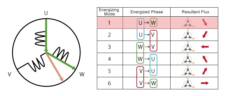
The above movement are acheived by contnuous change in current direction over two poles of stator at single time. but this is slighly not coninuous in their rotaion.
This makes motor vibration and noice will be produced.
so, to attain smooth continous rotation of rotor we have to control the current flow through all the three poles in same time. As shown below we can acheive continuous change in current flow in all stator poles at same time in 120 degree phase shift.
As we have seen, we drive BLD motors by continually changing the directionality of the flux produced by the coils. The permanent magnets on the rotor continually chase the shifting rotating magnetic field, causing the rotor to turn. this is the working of BLDC motor.
Advantages of BLDC motor:
- One big advantage is efficiency, as these motors can control continuously at maximum rotational force(Troque).
- Even small BLDC motors can deliver considerable power.
- BLDC motors can be controlled, using feedback mechanisms, to delivery precisely the desired torque and rotation speed.
- Reduce energy consumption and heat gerneration.
- BLDC motos also offer high durability and low electric noise gerneration.
- The sparks will not be produced as brushed motor between brushes and commutators.
Control of BLDC motor:
By using the inverter circuitry to also adust the voltage into each coil, we can control the magnitude of the current.
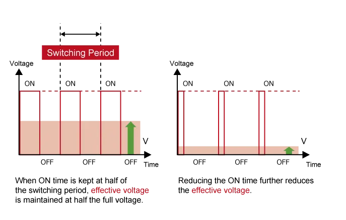
A typical way to adjust the voltage is with pulse with modulation. We alter the voltage by lengthening or reducing the pulse on time expressed as a ration of the ON+OFF switching interval. Increasing the duty cycle has the same effect as raising the votage, reducing the duty cycle has the same effect as lowering the current.
PWM can be implemented using MPUs equipped with dedicated PWM hardware. While 120 degree conducting control only requies Two-Phase voltage control.
Sinusoidal control uses three-Phase voltage control and is considerably more complicated as appropriate inverter circuitry is therefore essential for driving BLDC motors.