Week -2
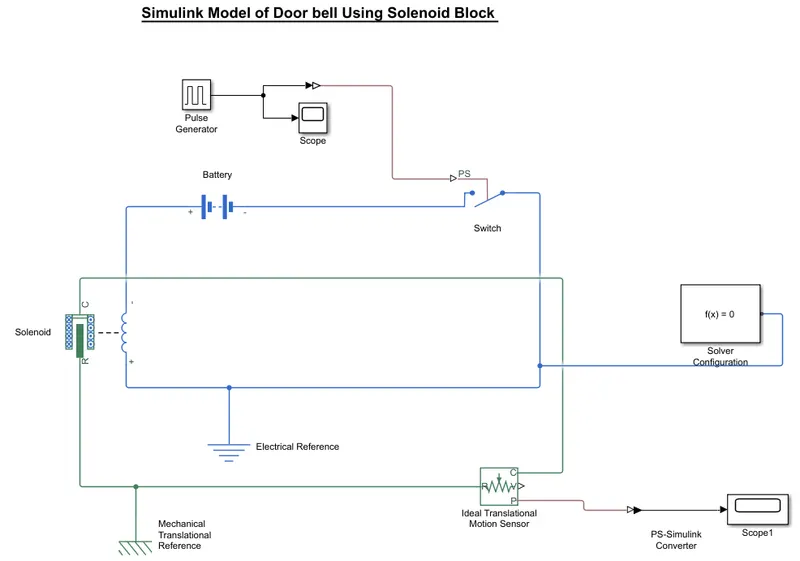
The Simulink Model developed file I attached Below but For Understanding the Diagram I used heare a Screenshot.
So we are talking about Door Bell using a solenoid Block First thing is come in our mind that this Bell is working on the Principle of Electromagnetism
Working of Solenoid :- When A Piece of wire is wrapped on a Iron and current through the wire the iron behaves as a magnet.
The above block diagram is similifed circuit of electric bell with a switch in Off Position.
Pulse Generator:- Here, we use a pulse generator which generate square wave pulse at regular interval of time with the pulse generator we use a Scope Block with the help of this block we are able to see that the given pulse is right or wrong. Block waveform Parameter
Ampitude=1
Period (sec)= 4
Pulse width=50
Phase Delay(sec)=4
Simulink to PS Convertor:- Used here to convert Simulink signal to pysical signal becouse our physical bock call Switch only working on Physical signal not on simulink signal.
Electrical source :- For Electrical source we are using a Battery of 12V which is connected to the Switch.
Switch Block :-Switch is used for compliting the circuit with a Threshold limit of 0.5. It is closed when the physical signal is greater than the Threshold value then the switch is closed otherwise is open.
Solenoid Block:- Solenoid Connected with switch and Battery, 'C' port of Solenoid with mechanical Reference.
Ideal Translational Sensor :- Sensor Connected with solenoid block 'R' to ovseve the movement of the Plunger.
PS to Simulink convertor:- This signal again chnage to simulink signal for scope to see the behaviour of graph.
Solver Configuration :- Each Pysical netwrok represented by a Connected simscape blocks requires slover setting information for simulation.
Process of the working of an Eeletric Bell
(a) When we pressed the switch the current start flow through the circuit.
(b) Due to this solenoid energied and due to flow of current the road inside the solenoid behave like a magnet and with the help of this it attracts the iron strip towards it due to strike the bell start ring.
(C) when the striking arm strikes the bell, the contact is broken and current stops flowing through the circuit and due to this electromagnet to lose its magnetic effect.
Input Signal Given thorugh Pulse Generator
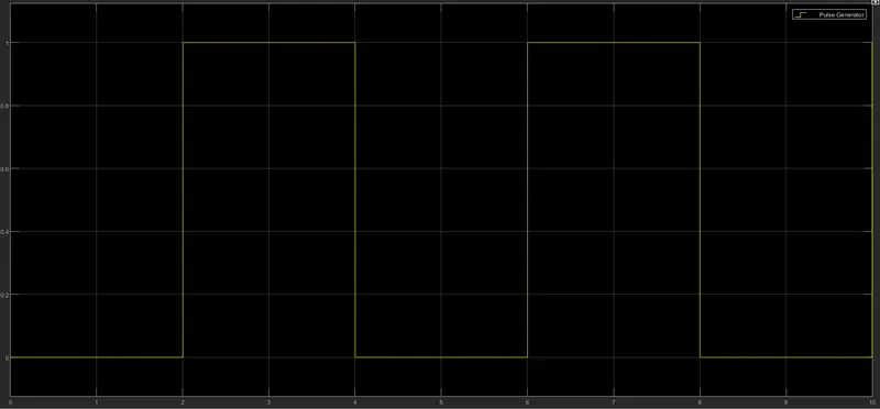
The above graph show that the switch will be closed at every 2 sec.
Plunger Movement
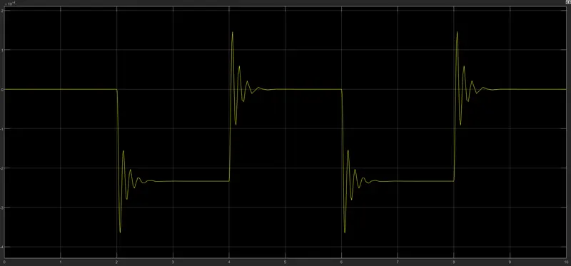
In this plot we can see at every 2 sec there is vibration in plots which shows that plunger moves down and hit the bell and bell is rang.
Question 2) Block diagarm of thermistor which is used to sense temprature of heater and on the fan at given condition.
(a) 20 degree C from 0 to 10 sec
(b) 27 degree C from 10 to 30 sec
(d) 25 degree C from to 30 t0 50 sec.
firstly we should know about that what is Thermistor
- Thermistors is a type of resistor whose electrical resistance varies with changes in temperature.
- Thermistors is a passive element
- Not work in extremely hot or cold temperatures
- It is ideal when a precise temperatures reading is required.
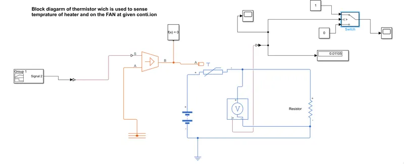
In this modelling we have used different type of components
- The fisrst block is the input block, wherein we using a singnla builder to given an input that is filtered
- The output of this subsystem is converted into physical signal by simulink PS onverter. and one scope is attached to examine the input.
- Now a controlled temperature source that will deliver the filered input onto the thermistor in the rspective itme intervals. It is alos gronded to the thermal reference.
- Now thermistor is connected to a DC battery source and a resistor and volage secsor connected in paralled. This voltae sensor and resistance connection is for finding the threshold voltage, which is the triggering value to make the fan ON/OFF
- Execute the threshold value using a scope and isplay blocks.
- Threshold value is 0.01106. or greater than (296.15k)
The input signal show below(Signal Builder)
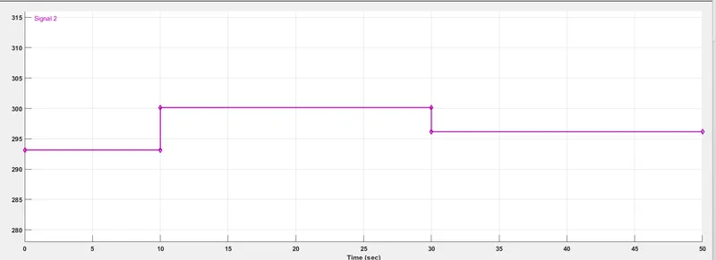
TIME SIGNAL VALUE(KELVIN)
0 TO 10 SEC 296.15
10 TO 30 SEC 300.15
30 TO 50 SEC 293.15
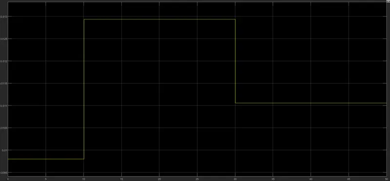
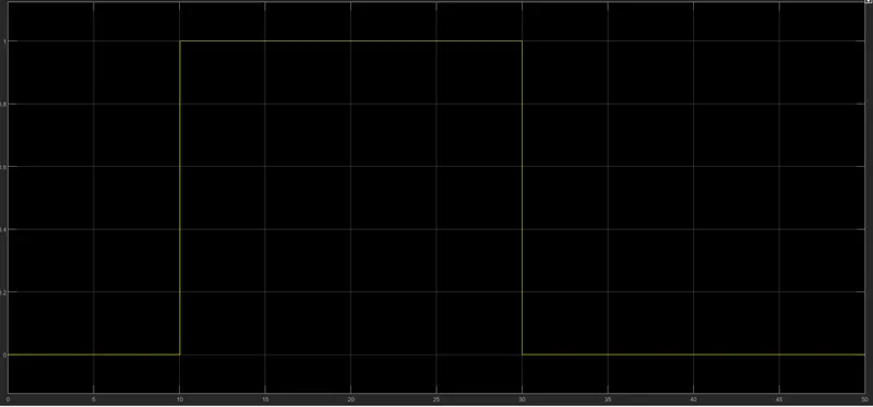
If Threshold value is greater than so it will give 1 value or it will give 0 value if it does not satifies the given condition. we design this condition with constant block.
(0 --- 10 sec) = FAN OFF = CONTANT 0
(10----- 30 sec) = FAN ON = CONTANT 1
(30----- 50 sec) = FAN OFF = CONTANT 0
Fan should be ON (10 to 30 sec)
DC motor positive terminal is connected to a controlled voltage source and the rotary part is connected to an ideal rotational motion sensor.
The output is taken form the sensor and it is shown on the scope