Week - 4
- A washing machine is a home appliance used ot wash laundary. Before we start the machine we need to consider the load of the clothes, such as how big the load is , what temperature the water will be for the wash and the rinse cycles, and also the machine runnng cycles.
- Initially fill the tub with clothes, based on the load or ny manually fil the tub with wate. Along with the water detergent is also added. Then once the water is filled sufficiently. the machine starts stirring the clothes continoulsy in both the direction.
- After few cycles of rotation, kthe remaining water form the clothes and as well as the tub.
- Similarly, this proess is repeated in order to rinse out the soap. Then again finally it flushes all the water out through drain house.
- Finally the spin is ON such that all the clothes inside gets dry to their maximum.
Stages of washing machine are:
- Soaking
- Washing
- Rinsing
- Drying
Model-1
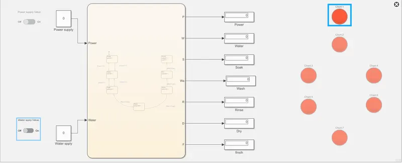
Logic-1
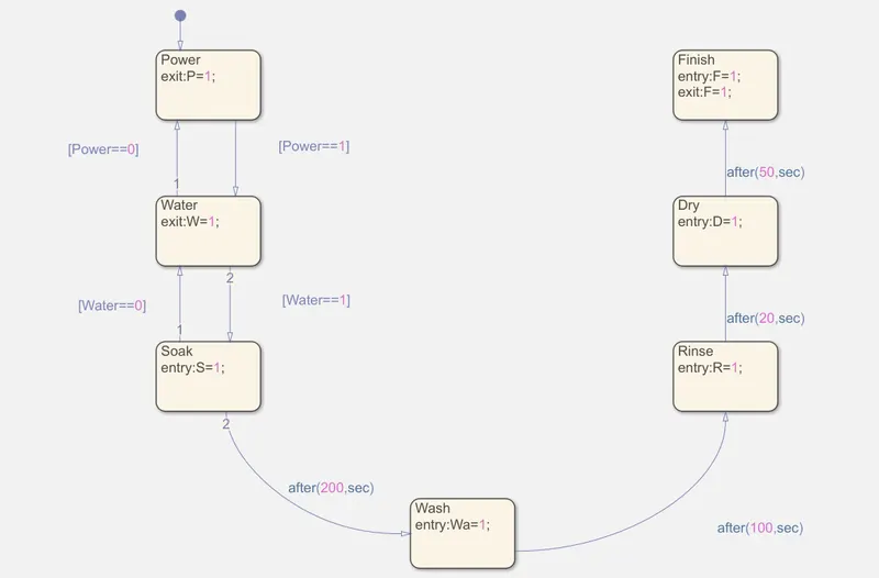
Logic that shows the washing machine process step by step without OFF condition.
Explanation:-
- firstly, we need to create a logic for the machine to RUN. For this create a chart by using 'CHART BLOCK' to define the logic of a Washing Machine.
- In order to start with logic in the charts form the left toolbar drag and drop the 'STAGE'.
- So, the first stage is the 'Water supply' and represented by 'W'. Here the water is filled based on the reqauirement.
- Between the power supply and water supply there is a condition that controls the process. If power is equal to 1 which means the power is ON. I f the power is ON, The water supply will start and when the power is at 0, then the it set to OFF, then there won't be any supply.
- The third stage is the Soaking Stage. this stage is activated only if the above conditions are in ON condition. In this stage the clothes are soaked once the water is filled. The condition here is if S=1 the state is going ON. The Soaking time is sround 200sec.
- The fifth state is the Rinsing stage. In this stae all the water is drained out completely. When this stage is running the condition is reepresented as 'R=1'. After 100 sec of washing time the clothes are rinsed of 20sec.
- The sixth stage is the Drying stage. When this stage is running the condition represented is 'D=1 the clothes are dried in this case. this druomg of clothes takes place after 20 sec of rinsing.
- Once this stage is stooped, it goes to the final stage that is 'Finsih stage'. After 50 sec of drying clothes the process reaches to the final stage that means the process ends and the machine is set to OFF.
- Here the main logic ends.
- In order ot provide the input parameters like power and water to the washing machine, choose towo constant block naming 'Power Supply' and 'Water supply'. These constant block are controlled by a slider switch. Here ON AND OFF are set to tune the parameters by connecting to the respective constant block.
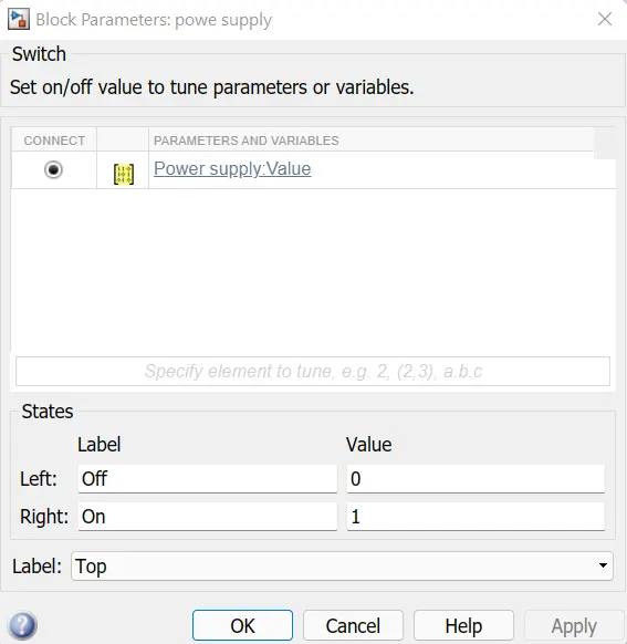
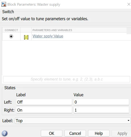
- So, the inputs are specifie.
- To the other side of the chart block create the required output parameter. The output parameters are Power(P), Water(W), Soak(S), Wash(Wa), Rinse(R), Dry(D), and finish(F).
- Now , from the tool bar select SIMYLATION>Go to PREPARE> go to drop down menu and select 'SYMBOLS PANE' from configuration and simulation option.
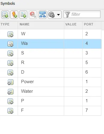
- For all the parameters we need to define the type of data it is , like the power(P) is the input Data, finish(F) is the Output Data etc.
- After delaring all the Variables to their respective data type, each one is connected to the display as shown in the model.
- finally, the 'LAMP BLOCK' is used to identify the stage process of the machine. For this drag and drop the lam block and double click on the block. Now select one parameter for each lamp block and link the respective signls to them. Also set the State and colour. if the state=1 then the lamp should indicate Green colour and if the state=0 then the loamp shoul indicate Red colour.
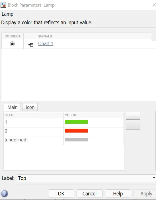
- Now, the complete model setuip is done.
- As per tge given conditions we need ot chnage the stop time to observe the LED glow based on their respective stages.
- Finally RUN the simulation as per the given time condition.
Results:-
Stages of Washing Machine:
Considering Stop time=100sec(baseline0), Power supply=1(ON) and Water Supply=O(OFF).
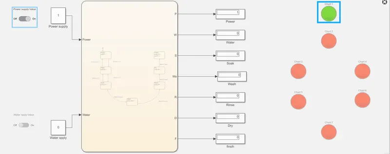
From the aboe image it is obseved that the power supply is kept ON and Water is kept OFF. As per the given condition when the water supply is kept OFF the whole process will not begin. Hence, Lamp assigned for the power glows up green and rest remains red.
Soaking:
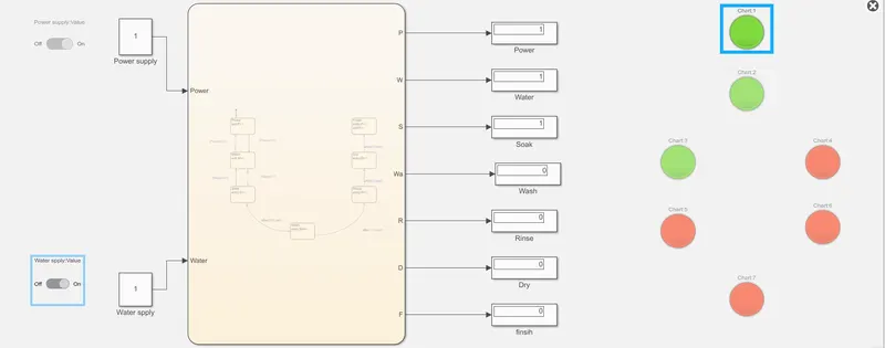
When both power and water supply are turned ON and the simulation is made to RUN for 100sec. it is obseved that hte soaking process is hapening and hence the lamp glow green for power, water and soaking. Rest all the lamp remains Red.
Washing:
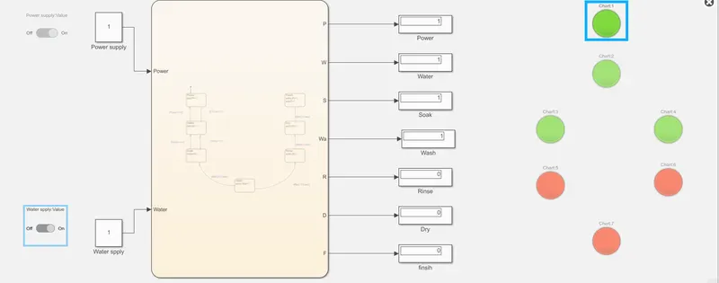
As per the given condition it is observed that as the water supply is turned ON, and the simulation is made to run for around 250sec( as soaking takes pace for 200sec) the washing process has begin after the soaking process ends. Hence lamp for washing also glows up Green and rest remains Red.
Rinising:
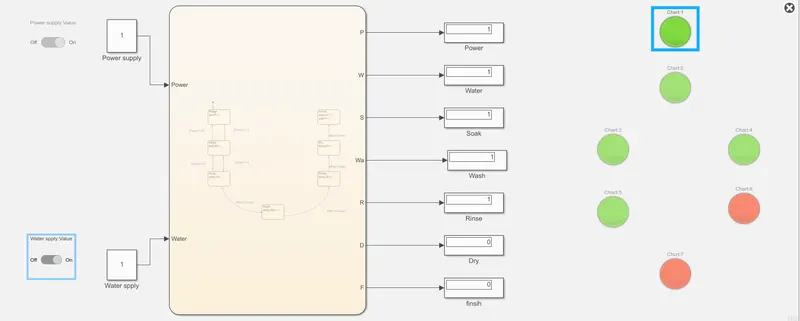
Once after completing the washing process for 100 sec, then immediately Rinsing process begins. Simulation is made to run for 320 sec as per the condition. Hence the Lamp also glows Green for the Rinsing stage and the lasts two stages remain Red.
Drying:
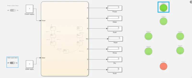
As the process of Rinsing Ends, immediately the next stage Drying is carried out and made to run for 350 sec. Hence the Lmap for the Drying also glows Green and the final stage remains Red.
Finished:
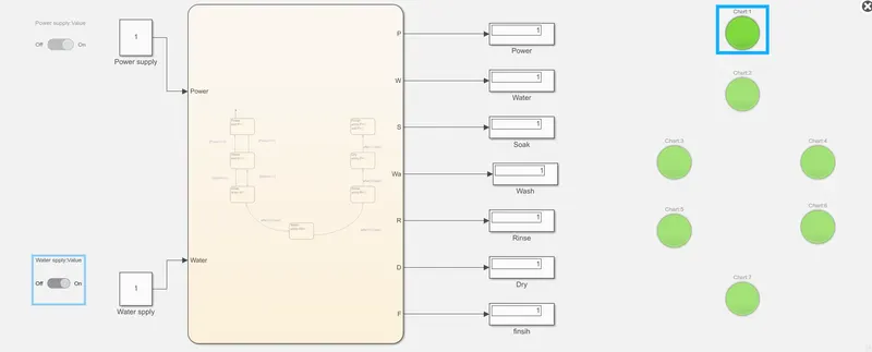
The above image shows the final stage of the complete process for the Washing Machine. The above model completely satisfies the given conditions and after finishing all the stages of the machine the 'Finish' Lamp glows Green. hence all the stages of washiung machine are performed using the given condition.
Model-2
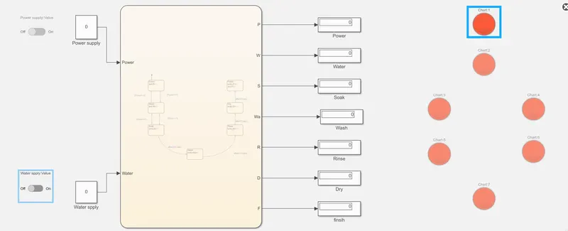
Logic:-
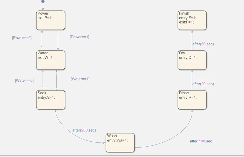
Explanation:-
- firstly, we need to creae a logic for the machine to RUN. for this create a chart by using 'CHART BLOCK' to define the logic of a Washing Machine.
- In order to start with logic, in the charts form the left toobar drag and drop the 'STAGE'.
- So, the first stage is the Power Supply. The power is used to control the ON and OFF the machine. if the power is ON, process follows step by step. Here Power is denoted by 'P'.
- The next stage is the 'Water Supply' and represented by 'W'. Here the water is filled based on the requirement.
- Between the power supply and water supply there is a condition that controls the process.i.e, if power is equal to 1 whcih means the power is ON. If the power is ON, the water supply will start and when the power is at 0, then the it set to OFF, then there won't be any supply.
- The third stage is the Soaking Stage i.e., Soak(s). this stage is activated only if the above conditions are in ON condition. In this stage the clothes are soaked once the water is filled. The conditon here is if S=1 the state is going ON. The Soaking time is around 200sec.
- The fourth stage is the Washing Stagei.e., Wash(w). Here as per the given condition the clothes are washed after 200 sec of soaking. As per the given criteria, the washing time is around 100sec.
- The fifth state is the Rinsing Stagei.e., Rinse(R). In this stage all the water is drained out comletely. When this stage is running the condition is represented as "R=1". After 100sec of washing time the clothes are rinsed for 20sec.
- the sixth stage is the Drying Stage i.e., Dry(D). When this stage is running the condition represented is D=1 the clothes are dried in this case. this drying of clothes takes place after 20sec of rinsing.
- Once this stage is stopped, it goes to the final stage that is 'finish stage' i.e, Finish(F). After 50 sec of drying clothes the process reaches to the final stage that means the process ends the machine is set to OFF.
- Here the main logic ends and the other connections are same as model-1
- The only change between model-1 and model-2 is , in model-1 for every stage the led glows green and remains green even after the porcess is finished. Whereas for model-2, the LED glows Green for the active stage and rest remains in RED.
Result:-
- The result for the model-2 is almost same as the model-1. It is obseved that when both power and water supply are in ON condition, the led lamp glows green and the soaking starts happening.
- As soaking time is around 200s ec, after 200sec the soaking process ends and washing process begins i.e., Led for Soaking procss turns Red and Led glows Green for washing.
- similarly, after 10 sec of washing the process ends and the led glows red which also starts the next process and hence led for rinsing gows Green.
- After 20sec of rinsing, the next stage is drying. The Drying stage lamp glows Green and lamp for drying goes red.
- Finally, after 50 sec of drying the process stops and hence the washing procss is completely done.
- Therefore, the lamp for finsih glow green which indicates that the process is done.
Conclusion:-
Therefore, the control logic of a Washing machine using staeflow is carried out as per the given input parameters. After all the processes have completed the final LED Glows to Green indicating that the processes has Ended.
Question-2 To make a Simulink chart fo rthe "Gear Shift" logic as per below condition:
Speed Range (Km/hr) Gear
0 to 15 1
16 to 25 2
26 to 40 3
41 to 60 4
Above 61 5
Solution BLOCKS USED:
1) Slider Switch
The Slider switch block toggles the value of the connected block parameter between two values during simulation.
2) Constant

Constant values are added here
3) Display
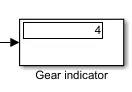
A display block is used to display the final output of the function.
4) State flow- chart
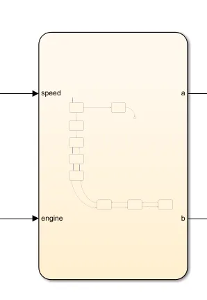
A state flow chart can be used as the action language to implement control logic.
5) Lamp

The lamp block displays a color indication the value of the input signal.
6) Slider block
The slider Block tunes the value of the connected block parameter during simulation.
7) Custom gauge
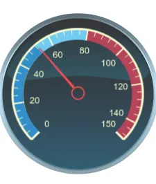
The coustom Gauge clokc displays the value of the connected signal on a gauge face that you can customize to look like a gauge in a real system.
SIMULINK MODEL:
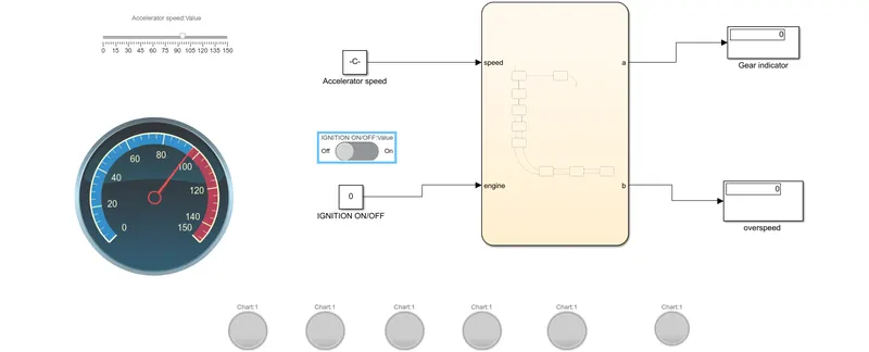
Overall structure-
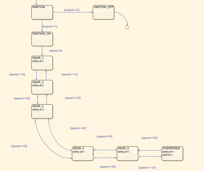
STATEFLOW-CHART:
EXPLANATION:
- The slider block is connected to a costant named "Accelerator speed".
- The stateflow chart is having two inputs which are spedd and engine. the speed input is connected with a constant named "Accelerator speed" and engine input is connected with a constat is connected to slider switch
- In stateflow chart, checking ignition condition, we take "engine" as input giving the condition as "engine==0" this will execute when the constant value is 0 that is when the vehicle is turned off and another condition as engine==1 this will execute when the constant value is 1 that is when the vehicle is turned on.
- After the ignition condition is turned on the state flows to the next processes. Speed conditions are defined for each block. When it exceeds the spedd condition the process flows to the next block. All the condition have been assigned to each block.
- The stateflow chart has two outputs named "a" and "b", these outputs are connected to the display blocks. The display block connected with the output "a" is named " GEAR INDICATOR" and the display block connected with the output "b" is named "OVERSPEED CONDITION".
- The "GEAR INDICATIOR" displlay block displays the exact gear at which the vehicle is running. Five lamps have been connected to this dsplay block in order to trun on the lamp for each geear ration. that is done by assigninig differenct state value for each lamp
- The "OVERSPEED CONDIOTION" Display block displays the condition when the vehicle is attaining overspeed situation.
WORKING DEMOSTRATION:
When the speed is below 16 km/hr:-
When the speed is below 25km/hr:-
When the speed is below 40 km/hr:-
When the speed is below 60 km/hr:-
When the speed is above 60 km/hr:-
when the speed is above 100 km/hr:-
RESULT:
Simulation of gear shift corresponding to the given speed range have been simulated successfully.