Week-7 Challenge: DC Motor Control
1. A. Speed control of a DC motor using BJT H-bridge
To create a chopping voltage and regulate the speed of a DC motor, an H-bridge simulation is employed. There are four BJT/Diode pairings in the H-bridge (BJT simulated by IGBT models). The simultaneous switching of Q1 and Q4 or Q2 and Q3 involves two transistors. When Q1 and Q4 are ON, a positive voltage is given to the motor, and when Q1 and Q4 are turned off, diodes D2-D3 function as free-wheeling diodes. When Q2 and Q3 are ON, a negative voltage is provided to the motor, and when Q2 and Q3 are turned off, the diodes D1–D4 function as free-wheeling diodes.
The motor starts with a 75% duty cycle and moves in the positive direction (mean DC voltage of 180V). The armature voltage abruptly reverses at time t=0.5 seconds, causing the motor to run in the other direction.
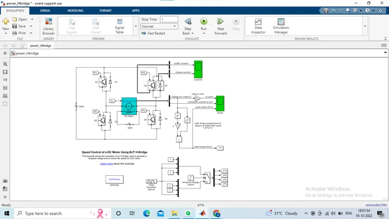
Currents displays the currents flowing in BJT Q3 and diode D3 as well as the motor speed, armature current, and load torque on the "Scope" display.
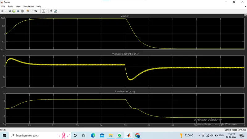
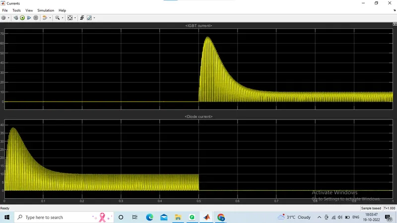
B. Initially at t=0 sec, positive voltage is applied the system. Hence, the forward flow of armature current shoots up and it results in acceleration of the motor. At t=0.5sec, negative voltage is applied. This results in reverse flow of armature ccurrent , which leads to deceleration of motor.
From the result, it is observed that the armature current shoots up in both positive and negative direction at t=0 and t=0.5sec. This is due to the effect of the change in polarity of the applied armature voltage.
C. The Four-Quadrant Chopper DC Drive (DC7) block’. Compare it with the H-bridge model.
The DC7 four-quadrant chopper DC drive during speed regulation is shown below:
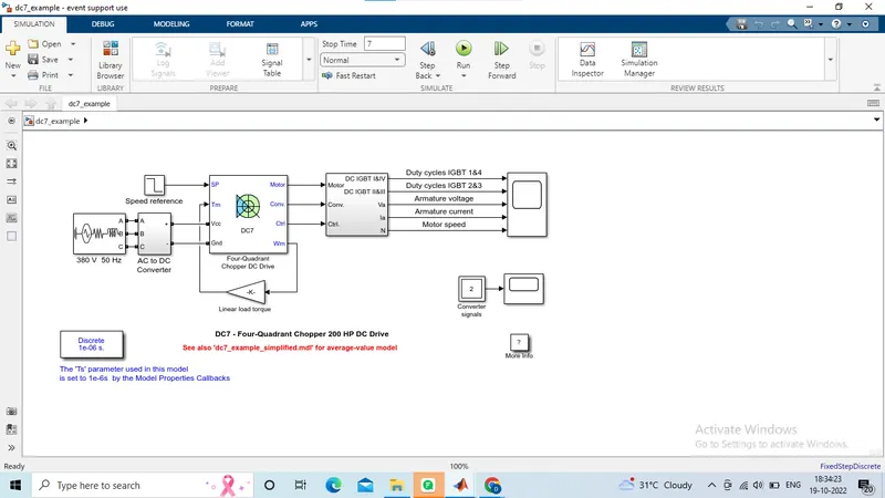
The 200 HP DC motor is separately excited with a constant 150 V DC field voltage source. The armature voltage is provided by an IGBT converter controlled by two PI regulators. The converter is fed by a 515 V DC bus obtained by rectification of a 380 V AC 50 Hz voltage source. In order to limit the DC bus voltage during dynamic braking mode, a braking chopper has been added between the diode rectifier and the DC7 block.
The first regulator is a speed regulator, followed by a current regulator. The speed regulator outputs the armature current reference (in p.u.) used by the current controller in order to obtain the electromagnetic torque needed to reach the desired speed. The speed reference change rate follows acceleration and deceleration ramps in order to avoid sudden reference changes that could cause armature over-current and destabilize the system. The current regulator controls the armature current by computing the appropriate duty ratios of the 5 kHz pulses of the four IGBT devices (Pulse Width Modulation). For proper system behaviour, the instantaneous pulse values of IGBT devices 1 and 4 are opposite to those of IGBT devices 2 and 3. This generates the average armature voltage needed to obtain the desired armature current. In order to limit the amplitude of the current oscillations, a smoothing inductance is placed in series with the armature circuit.
Simulation
Before starting the simulation, set the initial bus voltage to 515 V via the GUI block ('Initial States Setting' button and 'Cbus' variable).
Start the simulation. You can observe the motor armature voltage and current, the four IGBT pulses and the motor speed on the scope. The current and speed references are also shown.
The motor is coupled to a linear load, which means that the mechanical torque of the load is proportional to the speed.
The speed reference is set at 500 rpm at t = 0 s. Observe that the motor speed follows the reference ramp accurately (+400 rpm/s) and reaches steady state around t = 1.3 s.
The armature current follows the current reference very well, with fast response time and small ripples. Notice that the current ripple frequency is 5 kHz.
At t = 2 s, speed reference drops to -1184 rpm. The current reference decreases to reduce the electromagnetic torque and causes the motor to decelerate with the help of the load torque.
At t = 2.2 s, the current reverses in order to produce a braking electromagnetic torque (dynamic braking mode). This causes the DC bus voltage to increase.
At t = 3.25 s, the motor reaches 0 rpm and the load torque reverses and becomes negative. The negative current now produces an accelerating electromagnetic torque to allow the motor to follow the negative speed ramp (-400 rpm/s). At t = 6.3 s, the speed reaches -1184 rpm and stabilizes around its reference.
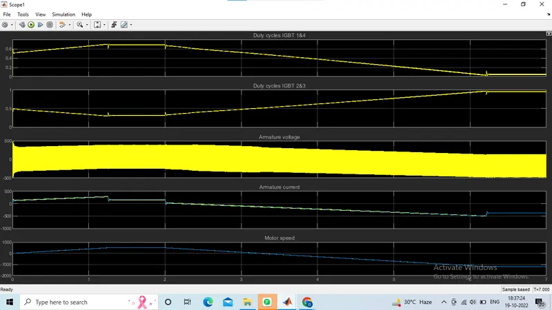
Comparison of 4-Q Chopper DC Drive (DC7) with H-bridge
- When utilising an H-bridge, the simulation is continuous; however, when using a four-quadrant chopper DC drive, the simulation is discrete.
- When compared to the DC7 block, the simulation time for the H-bridge is less because it uses continuous simulation.
- In an H-bridge circuit, altering the polarity of the motor can change its direction. In a four-quadrant chopper DC drive, changing the input signal to the DC7 block can change the motor's direction.
- The H-bridge circuit does not require the use of a snubber, but the DC7 block does. This is because a change in the input signal in the DC7 block causes a sharp increase in voltage.
-
By altering the duty cycle of the motor in the H-bridge circuit, the speed of the motor can be changed. In a DC drive using a DC7 block, the input signal or a speed reference can change the motor's speed.
-
Regenerative braking is possible in an H-bridge circuit but not in a DC drive for a four-quadrant chopper.
2. 2-quadrant chopper using simulink:
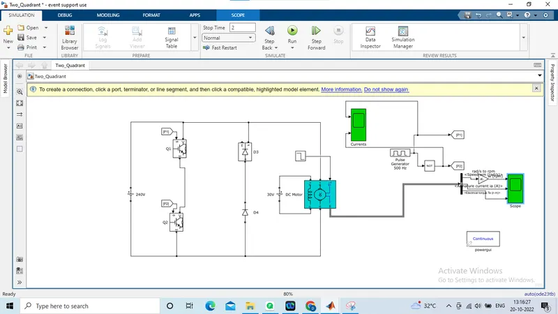
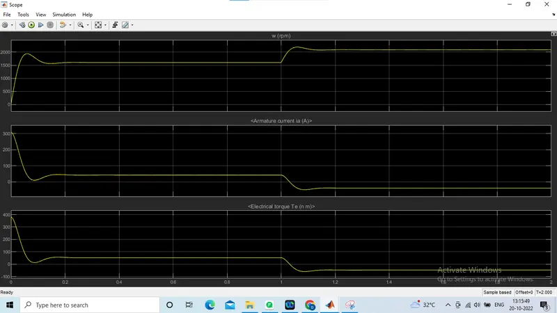
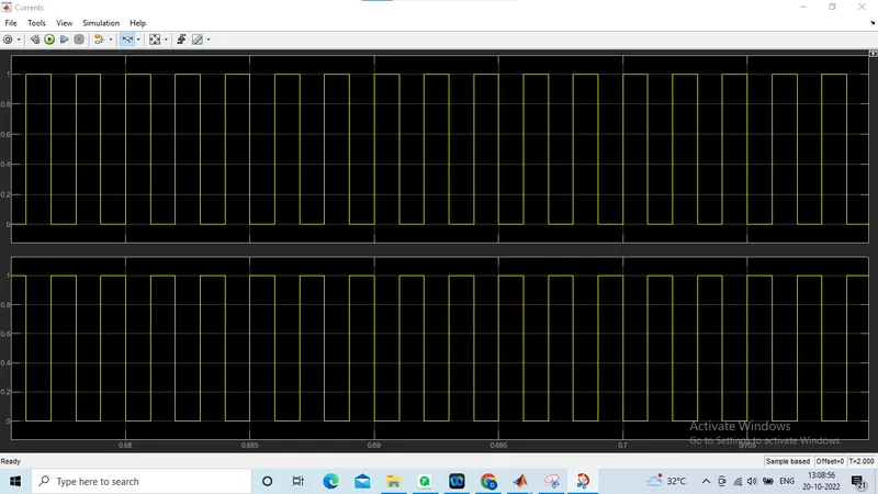
Simulation output:
As it is a 2-Q chopper, current flows in both positive and negative direction but the voltage remains positive always.
3.Operation of BLDC motor:
- A brushless DC electric motor (BLDC motor), also known as an electronically commutated motor or synchronous DC motor, is a Synchronous motor using a direct current (DC) electric power supply.
- The construction of a brushless motor system is typically similar to a permanent magnet synchronous motor (PMSM), but can also be a switched reluctant motor or an induction motor.
- Mostly, BLDC motors consist of three stator windings that are connected in star or ‘Y’ fashion (without a neutral point). Additionally, based on the coil interconnections, the stator windings are further divided into Trapezoidal and Sinusoidal Motors.
- In a trapezoidal motor, both the drive current and the back EMF are in the shape of a trapezoid. Since there are no brushes in a BLDC Motor, the commutation is controlled electronically.
- To rotate the motor, the windings of the stator must be energized in a sequence and the position of the rotor must be known to precisely energize a particular set of stator windings.
- A Hall Position Sensor is generally used to detect the position of the rotor and transform it into an electrical signal. Most BLDC Motors use three Hall Sensors that are embedded into the stator to sense the rotor’s position.
- The output of the Hall Sensor will be either HIGH or LOW depending on whether the North or South pole of the rotor passes near it. By combining the results from the three sensors, the exact sequence of energizing can be determined.
- The advantages of a brushless motor over a brushed motor are high power-to-weight ratio, high speed, nearly instantaneous control of speed (rpm) and torque, high efficiency, and low maintenance.
- Brushless motors find applications in such places as computer peripherals, hand-held power tools, and vehicles ranging from model aircraft to automobiles.