Week-7 Challenge: DC Motor Control
Answer:
1)
A. The demo model is opened up in the MATLAB and shown below,
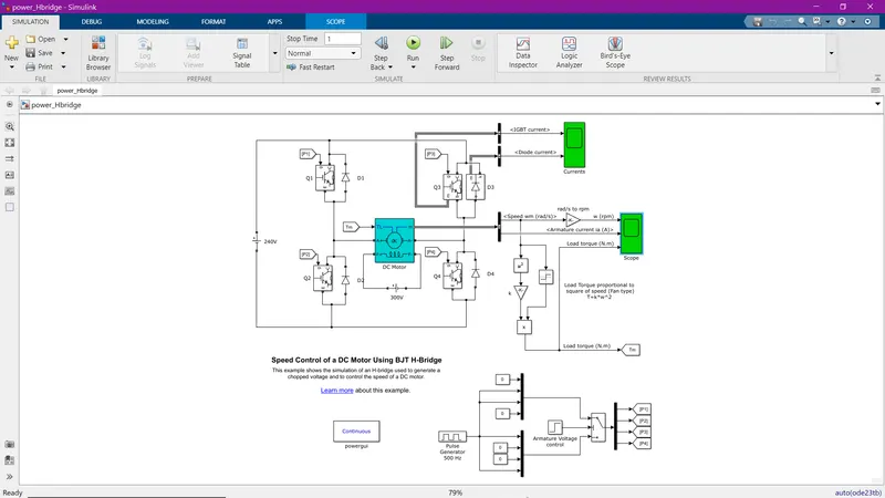
This model is used to control the speed of the DC motor using the BJT-H bridge.
As the title states, the power semiconductor device used for this operation is BJT.
Four BJTs are used to control the speed. The motor is placed in between all four BJTs which forms an H shape.
Two of these BJTs are fired simultaneously in the order of Q1 and Q4 or Q2 and Q3.
Four diodes are connected parallel to each of the BJTs to act as free-wheeling diodes when their corresponding switches are off.
These BJTs are fired by a signal generated by a pulse generator.
When Q1 and Q4 are fired, the supply voltage is supplied to the motor and the current flows in the positive direction in the motor. When Q2 and Q3 are fired, the voltage is applied to the motor but in a negative direction which means the current flows in the negative direction.
This is how the speed of the DC motor is controlled using the BJT-H bridge.
B.
The model is run and the output is shown below,
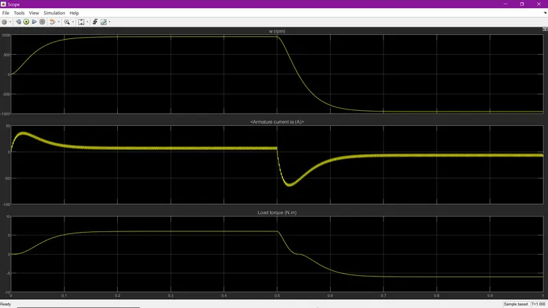
As you can see there is a shoot-up in the armature current. This is because when the polarity of the armature voltage is reversed when Q1 and Q4 are turned off and Q2 and Q3 are turned on at 0.5 seconds. When the polarity gets reversed, the armature current starts to flow in the negative direction. This is the reason why there is a shoot-up in the armature current.
C.
The Four-Quadrant Chopper DC Drive (DC7) block is opened and shown below,
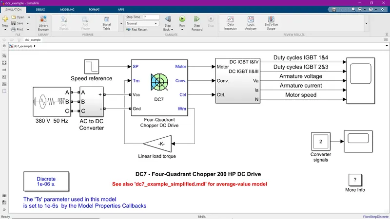
- Four-quadrant chopper is a DC-DC converter, whereas H-bridge is an electronic switch to change the polarity.
- The four-quadrant chopper DC drive operates in four regions namely, forward motoring(1st quadrant), forward braking(2nd quadrant), reverse motoring(3rd quadrant), and reverse braking(4th quadrant) whereas H-bridge operates only in two regions( forward motoring, forward braking).
- Regenerative braking is possible in the chopper circuit, whereas it is not possible in H-bridge.
- Four-quadrant chopper drive has more efficiency than the H-bridge due to its regenerative braking feature.
- H-bridge is used in applications like where the motor has to run in both directions, whereas the four-quadrant chopper drive is used for control circuits etc.
2)
- Before developing a 2- quadrant chopper, we must know what is a 2- quadrant chopper and how its works.
- 2- quadrant chopper is also called a Class C chopper.
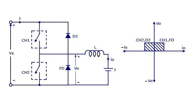
- The above figure is the circuit diagram of a 2- quadrant chopper and its operating regions.
- The 2- quadrant chopper consists of two power semiconductor devices and two diodes.
- As the name suggests, the chopper operates only in two operating regions (i.e,) First quadrant or Forward Motoring and Second quadrant or Forward braking.
- When chopper CH1 is switched ON, source Vs directly gets connected to the load and hence, load voltage Vo is equal to source voltage.
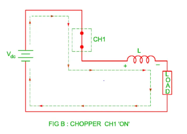
- The direction of load current from source to load as shown in the circuit diagram is positive.
- When CH1 is switched OFF, the free-wheeling diode FD comes into the circuit as it gets forward biased and hence shorts the load.
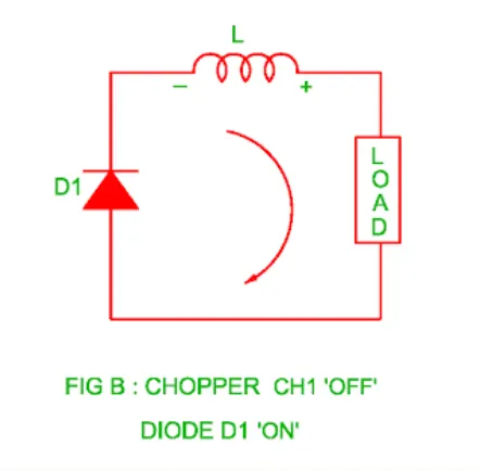
- Therefore, the output voltage Vo becomes zero.
- However, the io continues to die down through the FD and L in the same direction as shown in the circuit diagram.
- Thus, the average output voltage Vo and current Io are positive and hence operation of chopper is in first quadrant.
- When chopper CH2 is switched ON, load DC source E drives current through CH2 and load. The direction of this current io will be opposite to that shown in circuit diagram and hence the current is negative.
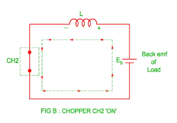
- Output voltage Vo is zero during this time.
- When CH2 is made OFF, diode D2 gets forward biased; hence, the current flows from the source from the load.
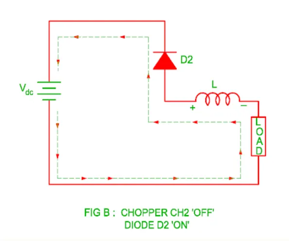
- The output voltage is Vs in this time as the load is connected to the source through D2 during OFF time of chopper CH2. Thus, the load current is always negative i.e. operation of chopper is within second quadrant.
With this circuit diagram, we developed a 2-quadrant DC chopper and is shown below,
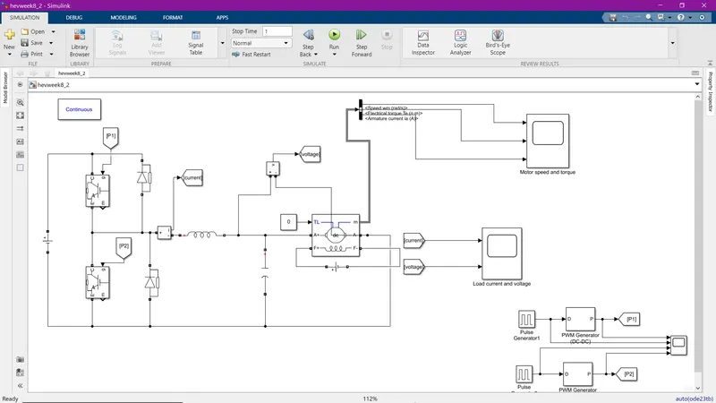
The DC machine is set to 5HP 20V 1750RPM Field:150V.
We chose IGBT as the power semiconductor device.
The gate signals for the IGBTs are generated by two pulse generators having two different phase delays.
One pulse generator gives a pulse signal at 0.1 sec and another one gives a pulse signal at 0.5 sec.
Both signals have an amplitude of 0.5, a period of 1 second, and a duty cycle of 20%.
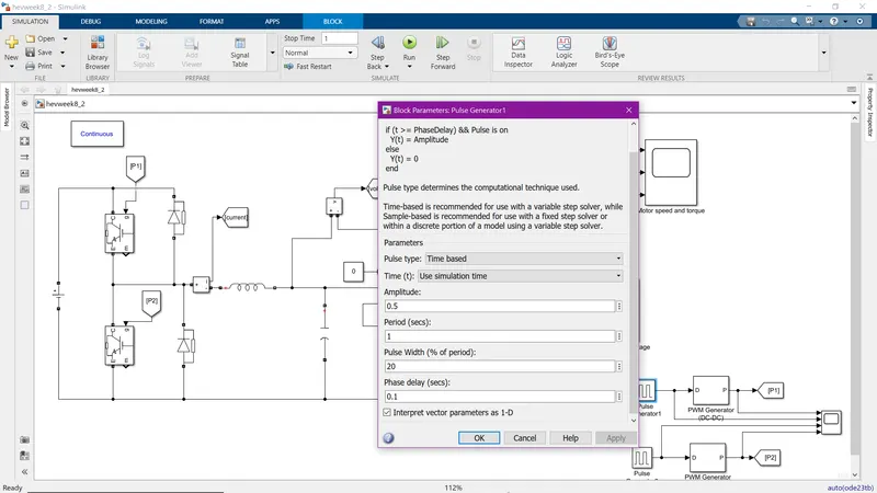
These signals are given to PWM generators which generates PWM signals.
The switching frequencies of these PWM generators are set to 50 Hz.
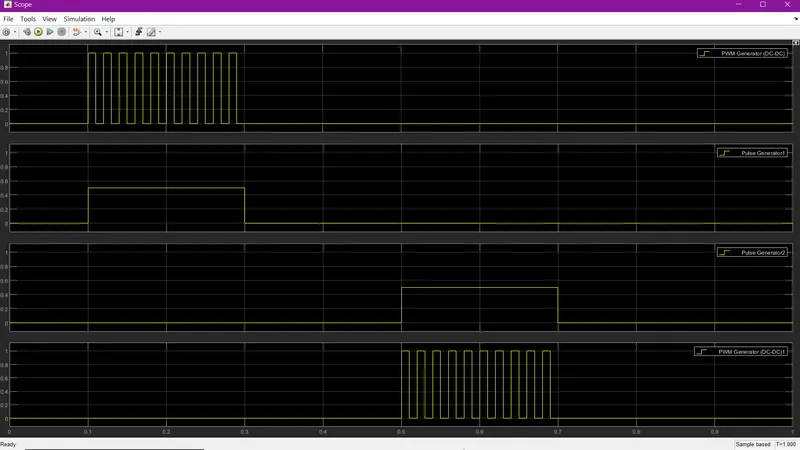
These two different PWM signals are taken as gate signals to CH1 and CH2.
An inductance is used to reduce the armature current ripple and a capacitor is used to reduce the voltage ripple.
Now the model is run and the load voltage and current are shown below,
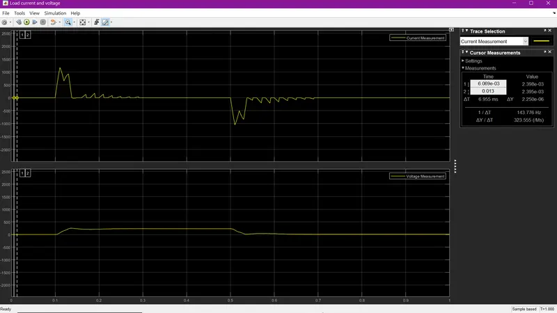
As you can see the IGBTs are not fired, therefore no current or voltage appears in the circuit.
At 0.1 second, CH1 is turned ON, therefore V and I appear in the circuit in a positive direction which is as per the operating region. (1st quadrant) V>0 and I>0
At 0.3 seconds, CH1 is turned OFF, but no voltage appears in the circuit because the FD starts conducting but current flows through FD.
At 0.5 seconds, CH2 is turned ON, therefore I appear in the circuit in a negative direction but V starts to decrease but stops at 0 which is as the operating region. (2nd quadrant) V>0 and I<0
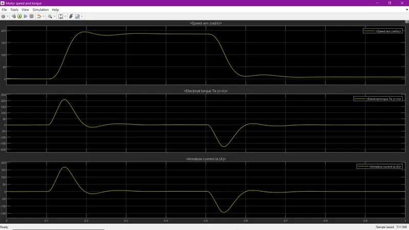
The speed. torque and armature current is also shown below,
3)
Operation of BLDC motor:
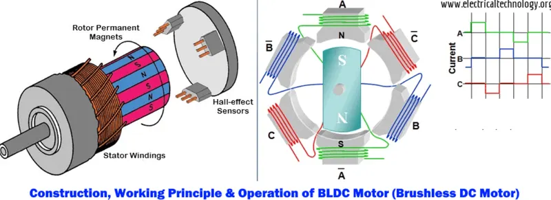
- BLDC motor is a permanent magnet synchronous motor driven by DC supply.
- BLDC motor accomplishes electronically controlled commutation system instead of a mechanically commutation system.
- BLDC motors are also referred to as trapezoidal permanent magnet motors.
- BLDC motor consists of permanent magnet rotor windings, stator windings, and hall sensors.
- BLDC motor works on the principle of Lorentz force law (i.e,) whenever a current carrying conductor placed in a magnetic field it experiences a force.
- Due to this force, the magnets will also experience equal and opposite force.
- In BLDC motor, the current-carrying conductor is stationary while the permanent magnet moves
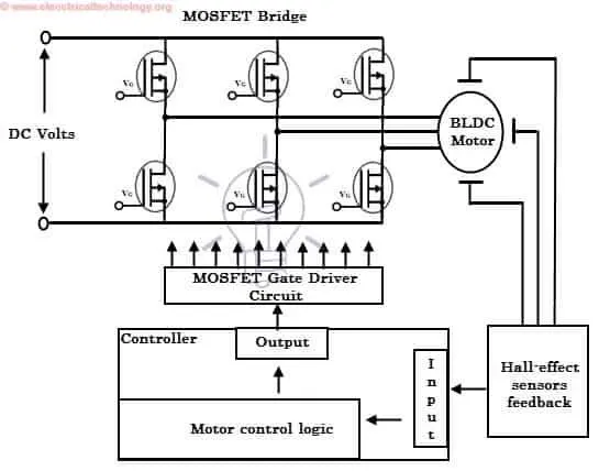
- The stator coils become electromagnet when they are electrically switched by a supply source and starts producing the uniform field in the air gap.
- Switching converts DC voltage to AC voltage waveform with trapezoidal shape.
- Due to the force of interaction between electromagnet stator and permanent magnet rotor, the rotor starts to rotate.
- The BLDC motor rotation depends on the switching sequence around the coils.
- The Hall sensors give shaft position feedback to the electronic controller unit.
- Based on this signal from sensor, the controller decides particular coils to energize.
- The Hall sensors generate Low and High level signals whenever rotor poles pass near to it.
- These signals form a switching sequence.
- The switching energizes the windings as North and South poles.
- The permanent magnet rotor with North and South poles align with stator poles causing motor to rotate.
- The BLDC motor produces torque because of the development of attraction forces and repulsion forces.