Week-7 Challenge: DC Motor Control
ANSWER 1.A : H bridge :
An H-bridge is a simple circuit that lets you control a DC motor to go backward or forward.
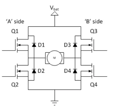
A DC motor spins either backward or forward, depending on how you connect the plus and the minus.
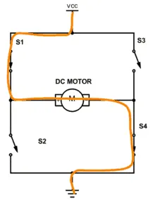
If you close switch 1 and 4, you have plus connected to the left side of the motor and minus to the other side. And the motor will start spinning in one direction.
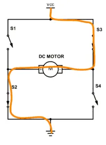
If you close switch 2 and 3, you have plus connected to the right side and minus to the left side. And the motor spins in the opposite direction.
Matlab demo model 'Speed control of a DC motor using BJT H- Bridge' below,
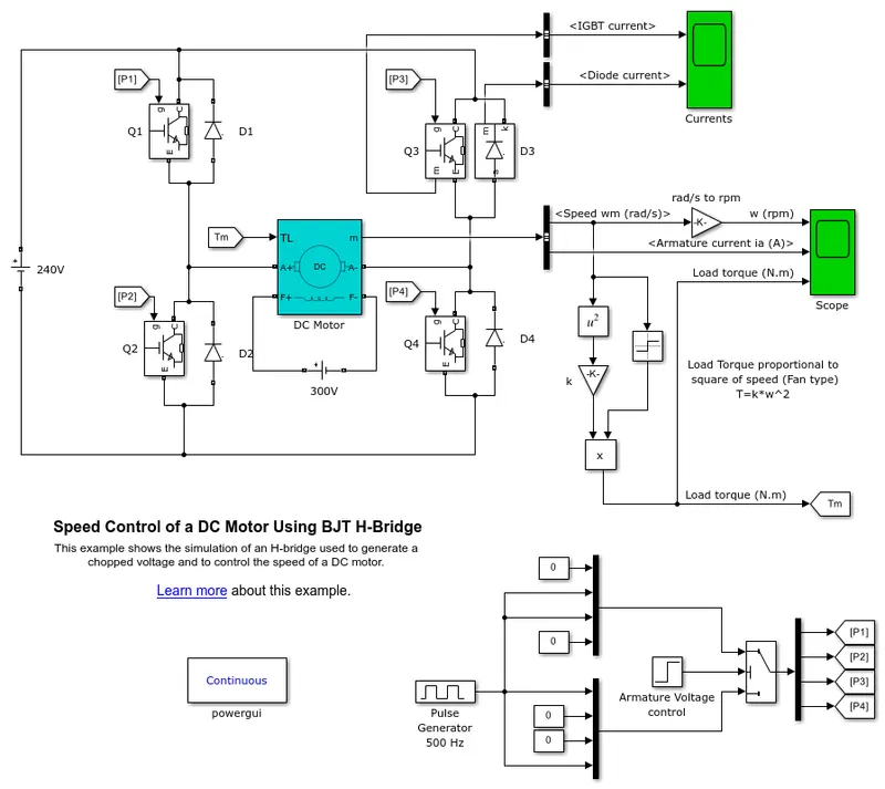
The bipolar junction transister (BJT) when used for power switching applications, operates as an IGBT. When it is conducting (BJT operating in the saturated region) a forward voltage Vf is developed between collector and emitter(in the range of 1 V) . Therefore , the IGBT block can be used to model the BJT device.The IGBT block does not simulate the gate current controlling the BJT or IGBT. The switch is controlled by a simulink signal (I/O).
- dc motor used is model is preset model(5 hp 24v 1750 rpm). It simulates a fan type of load (where load torque is proportional to square of speed). The armature mean voltage can be varied from 0 to 240 v when the duty cycle (specified in the pulse generator block) is varied from 0 to 100%.
- Two transisters are switched simultaneously : Q1 and Q4 or Q2 and Q3. When Q1 and Q4 are fired , a positive voltage is applied to the motor and diodes D2-D3 operate as freewheeling diodes when Q1 and Q4 are switched off.
- When Q2 and Q3 are fired , a negative voltage is applied to the motor and diodes D1-D4 operate as free wheeling diodes when Q2 and Q3 are switched off.
ANSWER 1.B:
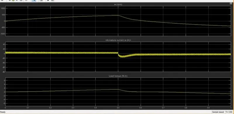
this is the scope results showing the armature current ,speed and load torque .
from the graph of armature current ,it is visible that there is increase in the armature current at 0sec and 0.5sec. the sudden surge in current values at 0sec and 0.5sec is due to the transient switching occuring in the circuit, as a results of which the direction of motor change from postive to negative after 0.5sec.
since there is already current flowing through the circuit in between 0 to 0.5 secs ,when there is a change in the switching the current willbe added to the already flowing current which
has changed its direction , which results in the spike at 0.5secs.
Here the initial current shoot up is due to sudden increase in voltage which inurns regulated by duty cycle.In this case motor driven in 75% of duty cycle.(i.e) 0.75*240= 180 V.
We can change the duty cycle to 50%(120 V) and seen the results as,
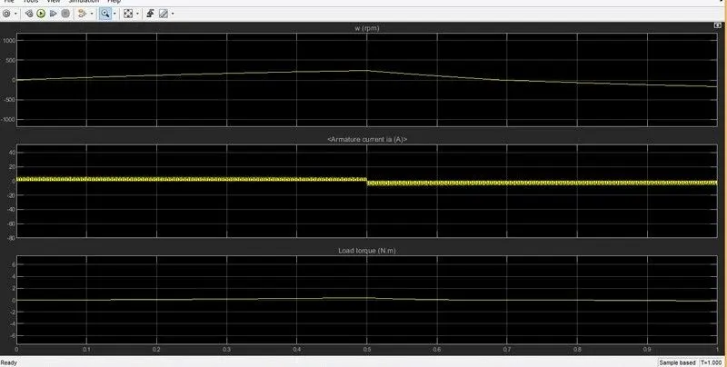
in the above graph , the duty cycle was changed and we can see that the surge in current has been decreased.The shoot up of current get dimlished on both the ends.
ANSWER1.C:
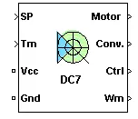
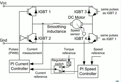
the four quadrant chopper dc motor uses speed controller ,current controller ,regulation switch and chopper .the four quadrant chopper is four quadrant dc-dc converter
converter ,where the supply is dc supply . this chopper has closed loop control with four quadrant operation .
four quadrant opertion :
1. forward motoring : motor rotates in clockwise direction and controller applies the drive in counter- clockwise .
2. Reverse motoring : motor rotates in counter clockwise and controller applies the drive counter clock wise .
3. forward regeneration : motor rotates in clockwise and controller appliesthe driven in counter clock wise .
4. Reverse regeneration : motor rotates in counter clockwise and controller applies the drive in clockwise .
Comparison of Four quadrant chopper and H-bridge:
- four quadrant chopper works in all quadrants , while h-bridge has only 2 operations in forward motoring and reverse motoring.
- In four quadrant chopper the current need to be transitted from one switch to another to change the direction of rotation, whereas in H-bridge, we can change the direction of motor, by changing the polarity of current.
- Four quadrant chopper has high switching frequency, while H-bridge has low switching frequency.
- Regenerative braking can be acheived in four-quadrant chopper, while it cannot be achieved in H-bridge.
- Four quadrant gives better efficiency and can operate at high power levels, while H-bridge works at moderate or lower power levels.
- Four Quadrant chopper is mainly used for industrial application or automobile application and H-bridge is mainly applicable in robotics.
- Vehicle control is better using Four-quadrant chopper than using H-bridge .
ANSWER :2 A DC-DC converter or chopper is a static device used to obtain variable dc voltage from constant dc voltage source. For a 2-quadrant chopper, the average voltage will be always positive, but the average load current might be positive or negative. For a 2-quadrant chopper, there will be 2 switching devices and 2 diodes. Two quadrant chopper are of two types : Class-C and Class-D
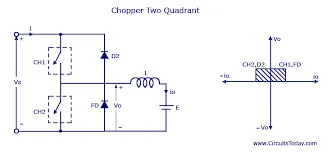
simulink model for two quadrant chopper :
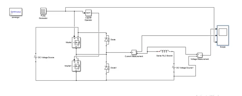
There are 2 MOSFETs and 2 Diodes are connected across the load. The input DC voltage is connected across the MOSFET-Diode configuration. The current measurement block and voltage measurement blocks are connected across the load, inorder to get the load current , load voltage and pulse generator and they are connected to the scope to get the plot of voltage and current. Pulse generator block is connected to give the trigger pulse for te Gate terminal of both the MOSFETs. A powergui block is given to simulate the model, since we are using Simscape™ Electrical™ Specialized Power Systems blocks. It stores the equivalent Simulink circuit that represents the state-space equations of the model.
Here we are changing the parameters of pulse generator, the duty cycle is changed to 50%, and the amplitude is changed to 10 and period is changed to 0.02 seconds to get the waveform with stop time of 1 seconds.
the output of model :
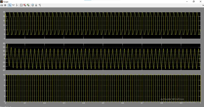
The output waveform clearly shows that the current on the load is positive in direction, whereas the output voltage will be both in positive and negative direction. This shows that the class-D chopper has output current in positive direction and the output voltage in both positive and negative half cycle.
ANSWER 3 : What is BLDC motor ?
A brushless DC motor (known as BLDC) is a permanent magnet synchronous electric motor which is driven by direct current (DC) electricity and it accomplishes electronically controlled commutation system (commutation is the process of producing rotational torque in the motor by changing phase currents through it at appropriate times) instead of a mechanically commutation system . The efficiency of BLDC motors is typically 85 to 90 percent, whereas as brushed type DC motors are 75 to 80 percent efficient. There are wide varieties of BLDC motors available ranging from small power range to fractional horsepower, integral horsepower and large power ranges.
construction of BLDC motor :
The main design difference between a brushed and brushless motors is the replacement of mechanical commutator with an electric switch circuit. Keeping that in mind, a BLDC Motor is a type of synchronous motor in the sense that the magnetic field generated by the stator and the rotor revolve at the same frequency.
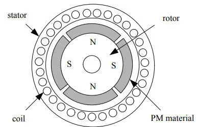
a BLDC Motor consists of two main parts: a stator and a rotor.
stator :The structure of the stator of a BLDC Motor is similar to that of an induction motor. It is made up of stacked steel laminations with axially cut slots for winding. The winding in BLDC are slightly different than that of the traditional induction motor.
Generally, most BLDC motors consists of three stator windings that are connected in star or ‘Y’ connection (without a neutral point).
rotor : The rotor part of the BLDC Motor is made up of permanent magnets (usually, rare earth alloy magnets like Neodymium (Nd), Samarium Cobalt (SmCo) and alloy of Neodymium, Ferrite and Boron (NdFeB)). Based on the application, the number of poles can vary between two and eight with North (N) and South (S) poles placed alternately.
working principle :
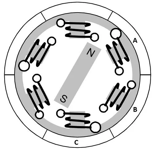
when a current is applied through a coil, a magnetic field is generated and the orientation of the field lines i.e. the poles of the generated magnet will depend on the direction of the current flowing through the coil. Using this principle, if we supply current to the coil A so that it will generate a magnetic field and attract the rotor magnet. The position of the rotor magnet will shift slightly clockwise and will align with A. If we now pass current through coils B and C one after the other (in that order), the rotor magnet will rotate in clock wise direction.
To increase efficiency, we can wind the opposite coils using a single coil so that we get double attraction. Further increasing the efficiency, we can energize two coils at the same time so that one coil will attract the magnet and the other coil will repel it. During this time, the third will be idle.
Advantages of BLDC motor:
- Higher efficiency
- High performance motor producing large torque
- Low rotor inertia leading to fast acceleration and deceleration
- Operate at high speed in all conditions
- Long life
- Less noise or noiseless operation