Week-7 Challenge: DC Motor Control
the Speed control of a DC motor using BJT H-bridge, we need to know about the components used in the circuit
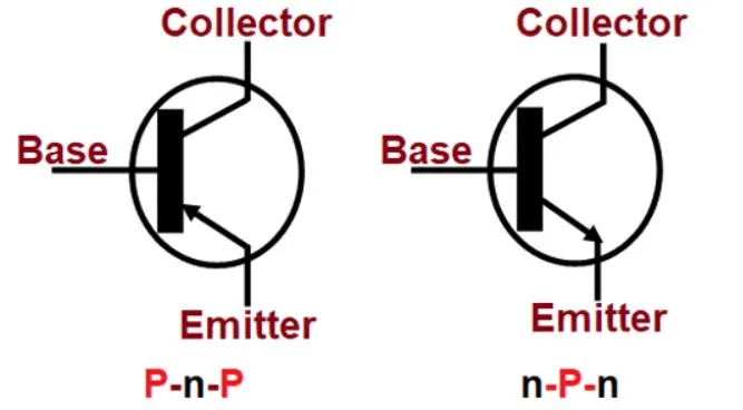
BJT - Bipolar Junction Transistors (BJT) are current regulating devices that control the amount of current flowing through them from the Emitter to the Collector terminals in proportion to the amount of biasing voltage applied to their base terminal, thus acting like a current-controlled switch.
MOSFET--
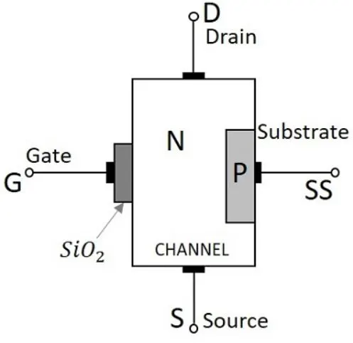
The MOSFET(Metal Oxide Semiconductor Field Effect Transistor) transistor is a semiconductor device widely used for switching and amplifying electronic signals in electronic devices. The MOSFET is a three-terminal device: source, gate, and drain.
IGBT --
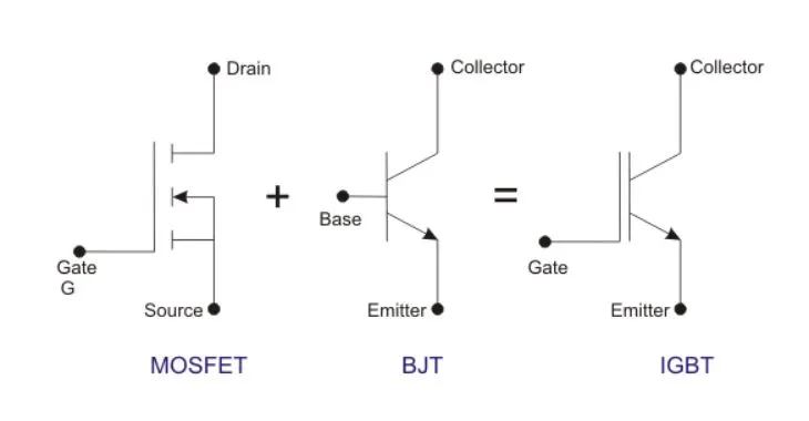
- An Insulated Gate Bipolar Transistor (IGBT) is a crucial component in what makes up a VFD (Variable Frequency Drive). An IGBT is the inverter element in a VFD, pulsing voltage faster than we can even blink. An IGBT is a semiconductor with three terminals that work as a switch for moving electrical current. Just as the word “gate” suggests, when voltage is applied to the gate, it opens or “turns on” and creates a path for current to flow between the layers. If no voltage is applied to the gate, or if the voltage is not high enough, the gate remains closed and there will be no flow of electricity. In this way, an IGBT behaves like a switch; on when the gate is open and flowing current and off when it is closed. Thus the IGBT acts as the switch used to create Pulse-Width Modulation (PWM). An IGBT will switch the current on and off so rapidly that less voltage will be channeled to the motor, helping to create the PWM wave.
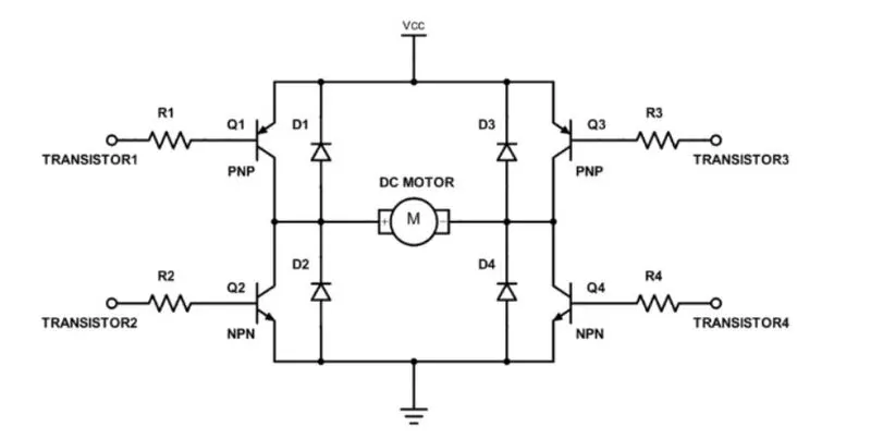
The H-bridge consists of four BJT/Diode pairs (BJT simulated by IGBT models). Two transistors are switched simultaneously: Q1 and Q4 or Q2 and Q3. When Q1 and Q4 are fired, a positive voltage is applied to the motor and diodes D2-D3 operate as free-wheeling diodes when Q1 and Q4 are switched off. When Q2 and Q3 are fired, a negative voltage is applied to the motor and diodes D1-D4 operate as free-wheeling diodes when Q2 and Q3 are switched off.
b.............
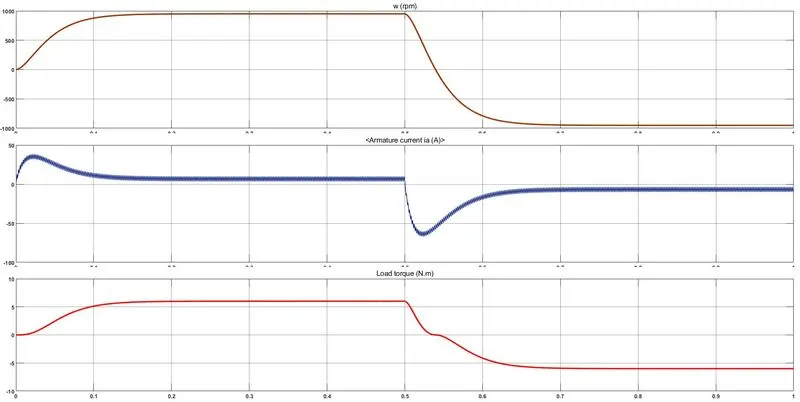
Pulse Width (% of period) : 75%
Initially, there is a spike in the armature current.
`I_a= (V-E_b)/R_a` where `I_a`is the armature current, `V`is the supply voltage , `E_b`is the back emf and `R_a`is the armature resistance.
At starting, Eb=0 as speed=0 at starting.
Therefore `I_a= V/R_a` and `R_a`is a very small value. Hence `I_a`is huge and that reflects in the graph.
.
.
.
.Pulse Width (% of period) : 50%
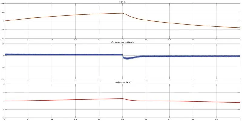
Therefore when pulse width decreases, the voltage applied across the DC motor decreases and the armature current finally decreases.
c................
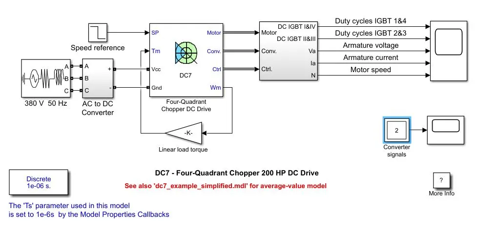
The Four-Quadrant Chopper DC Drive (DC7) block represents a four-quadrant, DC-supplied, chopper drive for DC motors.
The Four-Quadrant Chopper DC Drive block uses these blocks from the Electric Drives/Fundamental Drive Blocks library:
- Speed Controller (DC)
- Regulation Switch
- Current Controller (DC)
- Chopper
| H bridge | Four Quadrant chopper DC drive |
| Only Two quadrants of operation are possible. They are Forward motoring and reverse motoring | It can operate in all four quadrants (forward motoring, reverse regeneration, reverse motoring, and forward regeneration) |
| Higher armature current ripple. | Lower armature current ripple due to the high switching frequency of DC-DC converter |
| Less complex | More complex |
| Simulation is continuous and simulation time is more | Discrete and Simulation time is less |
| Widely Used in Robotics | Widely used in Automobile |
2..................
2-quadrant chopper using Simulink
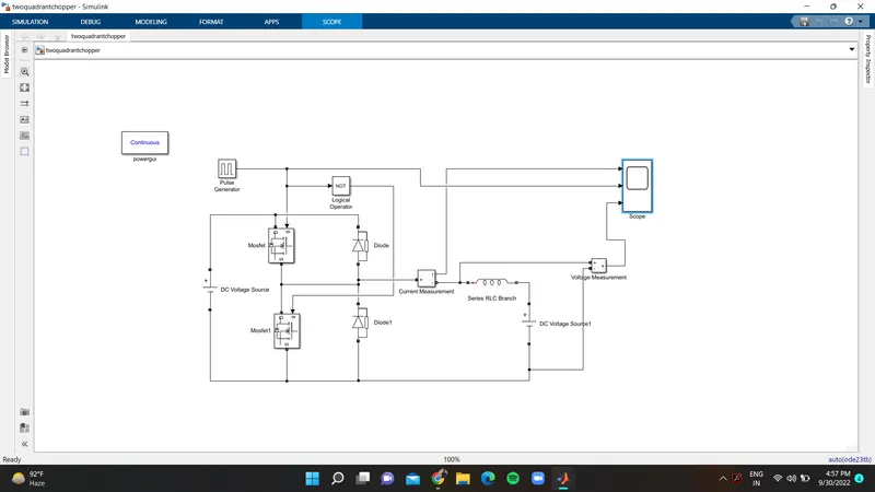
Class-C or Type-C Chopper is a category of the chopper that can operate in the first as well as a second quadrant. This basically means that the power can either flow from source to load or load to source in this chopper. This kind of chopper is also known as the Two Quadrant Class-A chopper.
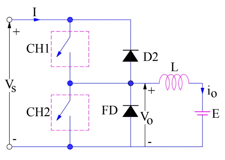
As we know that, a Class A and Class B chopper operates in the first and second quadrants respectively. Therefore, if we connect both these types of chopper in parallel then it is possible to have chopper operation in the first as well as a second quadrant. In fact, Class-C or Type-C chopper is obtained by the parallel connection of Class-A and Class-B chopper. The figure above shows the circuit diagram of this type of chopper.
We can notice that chopper CH1, free-wheeling diode (FD) and load are forming Class-A Chopper whereas chopper CH2, D2 and Load are forming Class-B chopper. Both these choppers are connected in parallel. To obtain first quadrant operation we should switch ON chopper CH1 and for getting second quadrant operation we should switch ON chopper CH2
Case 1----------
When chopper CH1 is switched ON, source Vs directly gets connected to the load and hence, load voltage Vo is equal to source voltage. The direction of load current is from source to load as shown in the circuit diagram which is assumed positive.
When CH1 is switched OFF, the free-wheeling diode FD comes into the circuit as it gets forward biased and hence shorts the load. Therefore, the output voltage Vo becomes zero. However, the io continues to die down through the FD and L in the same direction as shown in circuit diagram. Thus, the average output voltage Vo and current Io are positive and hence the operation of the chopper is in the first quadrant.
Case 2: .........
When chopper CH2 is switched ON, load DC source E drives current through CH2 and load. The direction of this current io will be opposite to that shown in circuit diagram and hence is assumed negative. Output voltage Vo is zero during this time. When CH2 is made OFF, diode D2 gets forward biased and hence the current into the source from the load. The output voltage is Vs in this time as the load is connected to the source through D2 during OFF time of chopper CH2. Thus, the load current is always negative i.e. operation of chopper is within second quadrant.
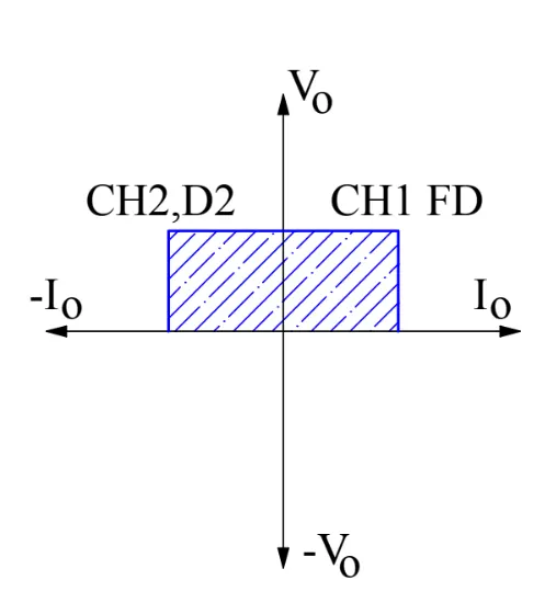
The average load voltage is always positive but the average load current may be positive or negative. Therefore, power flow may be from the source to load (first quadrant operation) or load to source (second quadrant operation). The operating region of Class-C or Type-C chopper is shown by hatched area.
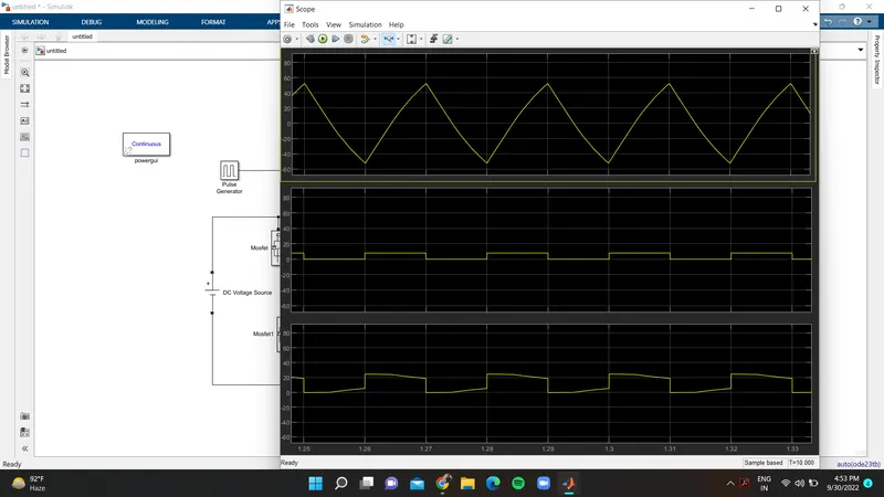
the simulation is run for 10 sec and the source voltage applied is 24v and the vout voltage is about 12v
the voltage is always positive but the current becomes both positive and negative. Hence, the Type C chopper is simulated and verified.
3.....................
BLDC motor.
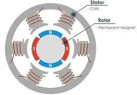
BLDC motor stands for Brushless Direct Current Motor and as the name suggests, it works on direct current electricity. BLDC motor uses permanent magnets, instead of electromagnets that are used in conventional motors. The permanent magnets of BLDC motors have less energy and heat losses compared to electromagnets.
efficiency is the most important feature of BLDC motors. Because the rotor is the sole bearer of the magnets and it doesn’t require any power. i.e. no connections, no commutator and no brushe
Construction:
In this motor, the permanent magnets attached to the rotor. The current-carrying conductors or armature windings are located on the stator. They use electrical commutation to convert electrical energy into mechanical energy. The main design difference between brushed and brushless motors is the replacement of a mechanical commutator with an electric switch circuit. A BLDC Motor is a type of synchronous motor in the sense that the magnetic field generated by the stator and the rotor revolve at the same frequency.
The Brushless motor does not have any current carrying commutators. The field inside a brushless motor is switched through an amplifier which is triggered by the commutating device like an optical encoder.
Working:
BLDC motor works on the principle similar to that of a Brushed DC motor. The Lorentz force law which states that whenever a current-carrying conductor is placed in a magnetic field it experiences a force. As a consequence of reaction force, the magnet will experience an equal and opposite force. In the BLDC motor, the current carrying conductor is stationary and the permanent magnet is moving.
When the stator coils get a supply from the source, it becomes an electromagnet and starts producing the uniform field in the air gap. Though the source of supply is DC, switching makes to generate an AC voltage waveform with a trapezoidal shape. Due to the force of interaction between the electromagnet stator and permanent magnet rotor, the rotor continues to rotate.