Week-7 Challenge: DC Motor Control
AIM:
1. A. Explain a MATLAB demo model named ‘Speed control of a DC motor using BJT H-bridge’.
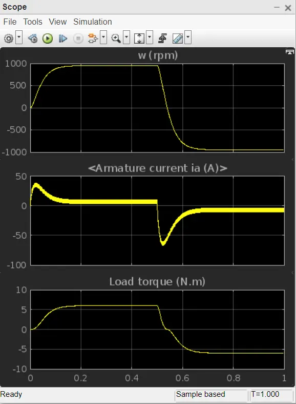
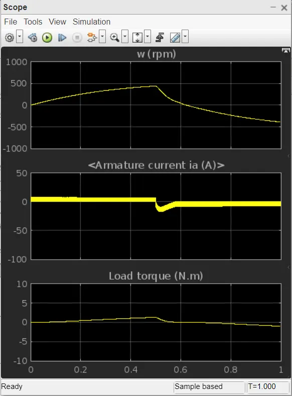
B. Comment on the armature current shoot-up from the scope results.
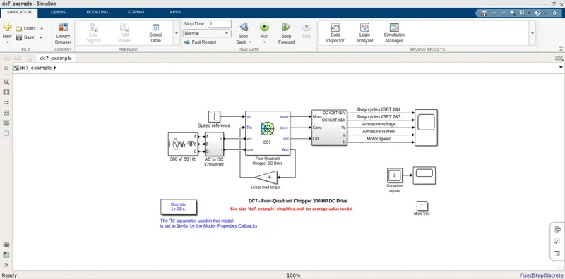
C. Refer to the help section of ‘The Four-Quadrant Chopper DC Drive (DC7) block’. Compare it with the H-bridge model.
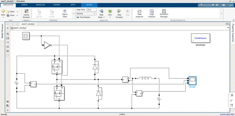
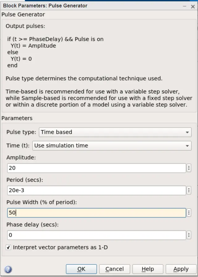
2. Develop a 2-quadrant chopper using simulink & explain the working of the same with the relevant results. (Refer to article - Multiquadrant operation of motor )
3. Explain in a brief about operation of BLDC motor.
study 1:
H-BRIDGE:
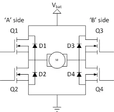
The switching elements (Q1..Q4) are usually bi-polar or FET transistors, in some high-voltage applications IGBTs. Integrated solutions also exist but whether the switching elements are integrated with their control circuits or not is not relevant for the most part for this discussion. The diodes (D1..D4) are called catch diodes and are usually of a Schottky type.
The top-end of the bridge is connected to a power supply (battery for example) and the bottom-end is grounded.
In general all four switching elements can be turned on and off independently, though there are some obvious restrictions.
Though the load can in theory be anything you want, by far the most pervasive application if H-bridges is with a brushed DC or bipolar stepper motor (steppers need two H-bridges per motor) load. In the following I will concentrate on applications as a brushed DC motor driver.
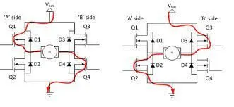
The basic operating mode of an H-bridge is fairly simple: if Q1 and Q4 are turned on, the left lead of the motor will be connected to the power supply, while the right lead is connected to ground. Current starts flowing through the motor which energizes the motor in (let’s say) the forward direction and the motor shaft starts spinning.
If Q2 and Q3 are turned on, the reverse will happen, the motor gets energized in the reverse direction, and the shaft will start spinning backwards.
In a bridge, you should never ever close both Q1 and Q2 (or Q3 and Q4) at the same time. If you did that, you just have created a really low-resistance path between power and GND, effectively short-circuiting your power supply. This condition is called ‘shoot-through’ and is an almost guaranteed way to quickly destroy your bridge, or something else in your circuit.
MODEL DESCRIPTION:
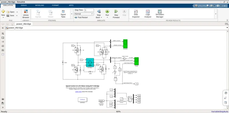
Model has a DC motor, which is controlled by four IGBTs arranged in H shape bridge. The model has catching diode also, which bears back emf and prevents switches from burning. IGBTs are controlled by a signal. When Q1, Q4 is fired, positive voltage is applied to motor and rotor rotates in forward direction and when Q2, Q4 is fired, negative voltage is applied to motor and rotor rotates in reverse direction.
Comparison:
|
Four-Quadrant Chopper DC Drive |
H-bridge model |
|
Four quardrant operation is possible. |
Two quardrant operation is possible. |
|
forward, reverse - monitoring and regenerating |
forward,reverse - monitoring |
|
More complex |
Less complex |
|
Discrete and stimulation time is less |
Continous stimulation and stimulation time is more |
|
Regenerative braking is possible |
Regenerative braking is not possible |
Study 2:
2-quadrant chopper:
Pulse Generator:
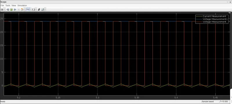
50% Duty Cycle:
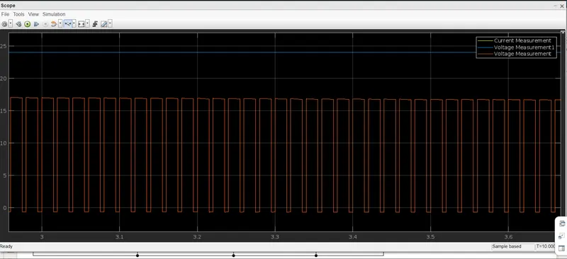
75% Duty Cycle:
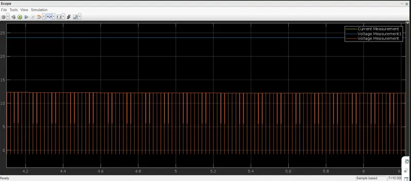
100% Duty Cycle:
Study 3:
Brushless DC Motors
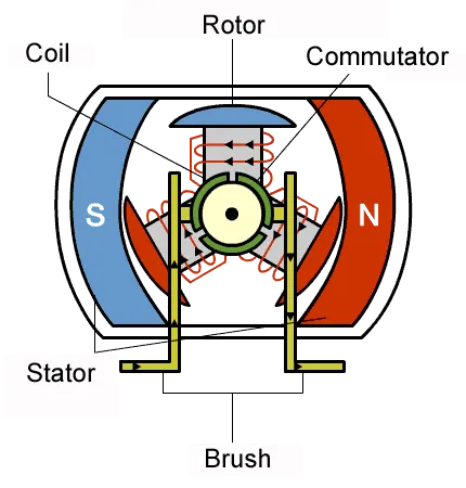
The simplest type of motor is the brushed DC motor. In this type of motor, electrical current is passed through coils that are arranged within a fixed magnetic field. The current generates magnetic fields in the coils; this causes the coil assembly to rotate, as each coil is pushed away from the like pole and pulled toward the unlike pole of the fixed field. To maintain rotation, it is necessary to continually reverse the current so that coil polarities will continually flip, causing the coils to continue “chasing” the unlike fixed poles. Power to the coils is supplied through fixed conductive brushes that make contact with a rotating commutator; it is the rotation of the commutator that causes the reversal of the current through the coils. The commutator and brushes are the key components distinguishing the brushed DC motor from other motor types.
Fixed brushes supply electric energy to the rotating commutator. As the commutator rotates, it continually flips the direction of the current into the coils, reversing the coil polarities so that the coils maintain rightward rotation. The commutator rotates because it is attached to the rotor on which the coils are mounted.
Brushed DC motors, featuring simple design and easy control, are widely used to open and close disk trays. In cars, they are often used for retracting, extending, and positioning electrically-powered side windows. The low cost of these motors makes them suitable for many uses. One drawback, however, is that brushes and commutators tend to wear relatively quickly as a result of their continued contact, requiring frequent replacement and periodic maintenance.
A stepper motor is driven by pulses; it rotates through a specific angle (step) with each pulse. Because the rotation is precisely controlled by the number of pulses received, these motors are widely used to implement positional adjustments. They are often used, for example, to control paper feed in fax machines and printers—since these devices feed paper in fixed steps, which are easily correlated with pulse count. Pausing can also be easily controlled, as motor rotation stops instantly when the pulse signal is interrupted.
With synchronous motors, rotation is synchronous with the frequency of the supply current. These motors are often used to drive the rotating trays in microwave ovens; reduction gears in the motor unit can be used to obtain the appropriate rotational speeds to heat food. With induction motors, too, the rotation speed varies with frequency; but the movement is not synchronous. In the past, these motors were often used in electric fans and washing machines.
Working of BLDC Motors
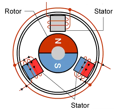
As their name implies, brushless DC motors do not use brushes. With brushed motors, the brushes deliver current through the commutator into the coils on the rotor. So how does a brushless motor pass current to the rotor coils? It doesn’t—because the coils are not located on the rotor. Instead, the rotor is a permanent magnet; the coils do not rotate, but are instead fixed in place on the stator. Because the coils do not move, there is no need for brushes and a commutator.
With the brushed motor, rotation is achieved by controlling the magnetic fields generated by the coils on the rotor, while the magnetic field generated by the stationary magnets remains fixed. To change the rotation speed, you change the voltage for the coils. With a BLDC motor, it is the permanent magnet that rotates; rotation is achieved by changing the direction of the magnetic fields generated by the surrounding stationary coils. To control the rotation, you adjust the magnitude and direction of the current into these coils.
Since the rotor is a permanent magnet, it needs no current, eliminating the need for brushes and commutator. Current to the fixed coils is controlled from the outside.
Advantages of BLDC Motors
A BLDC motor with three coils on the stator will have six electrical wires (two to each coil) extending from these coils. In most implementations three of these wires will be connected internally, with the three remaining wires extending from the motor body (in contrast to the two wires extending from the brushed motor described earlier). Wiring in the BLDC motor case is more complicated than simply connecting the power cell’s positive and negative terminals; we will look more closely at how these motors work in the second session of this series. Below, we conclude by looking at the advantages of by BLDC motors.
One big advantage is efficiency, as these motors can control continuously at maximum rotational force (torque). Brushed motors, in contrast, reach maximum torque at only certain points in the rotation. For a brushed motor to deliver the same torque as a brushless model, it would need to use larger magnets. This is why even small BLDC motors can deliver considerable power.
The second big advantage—related to the first—is controllability. BLDC motors can be controlled, using feedback mechanisms, to delivery precisely the desired torque and rotation speed. Precision control in turn reduces energy consumption and heat generation, and—in cases where motors are battery powered—lengthens the battery life.
BLDC motors also offer high durability and low electric noise generation, thanks to the lack of brushes. With brushed motors, the brushes and commutator wear down as a result of continuous moving contact, and also produce sparks where contact is made. Electrical noise, in particular, is the result of the strong sparks that tend to occur at the areas where the brushes pass over the gaps in the commutator. This is why BLDC motors are often considered preferable in applications where it is important to avoid electrical noise.