DC Motor Control
AIM:
- To Modify the model ‘Speed control of a DC motor using BJT H-bridge’ such that armature current doesn’t shoot up when motor changes direction from forward to reverse.
- To compare ‘The Four-Quadrant Chopper DC Drive (DC7) block’ with H-bridge model.
- To make a suitable EV model using DC7 block and make result report.
OBJECTIVE:
To understand the power electronics involved in the controlling of the motor.
SOLUTION:
A. To Modify the model ‘Speed control of a DC motor using BJT H-bridge’ such that armature current doesn’t shoot up when motor changes direction from forward to reverse.
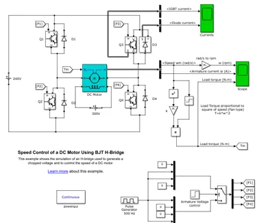
The H-bridge configuration facilitates the motor operation in two quadrants: Forward motoring & reverse motoring.
The H-bridge model uses 4 BJTs to allow the 2-quadrant operation of the DC motor. The Transistors Q1 & Q4 are triggered simultaneously and Q2 & Q3 remain off for the same time. Q1 & Q4 conduct when the armature voltage is positive, causing the motor to rotate in the positive direction i.e. the current flows from the voltage source through Q1 to the motor and returns through Q4. When the armature voltage reverses, Q1 & Q4 get reverse biased and turn off, whereas Q2 & Q3 turn on which reverses the direction of the current through the motor and the motor runs in the negative direction.
Now, when the motor changes its direction i.e. when the armature voltage changes its polarity and the direction of the current changes, a large current transient (about 5 times) appears in the circuit owing to the sudden reversal of polarity of the armature voltage. This current transient can be observed in the figure below:
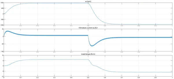
To improve the response of the current of the motor for change in direction, we can add an inductor in series with the armature of the motor. This inductance has very little effect on the current peak transient but it reduces the steady state current ripple. Higher values of inductance would be needed to get the desired response which is not feasible. The inductor further impacts the torque and speed of the motor which is not desirable.
A better solution can be obtained by reducing the duty cycle. Duty cycle is the ratio of time a load or circuit is ON compared to the time the load or circuit is OFF. Duty cycle, sometimes called "duty factor," is expressed as a percentage of ON time.
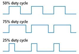
This can be done by changing the pulse width of the pulse generator to a lower value. The following results show that reducing the pulse width to 50% i.e. a duty cycle of 50% will help in reducing current shoot-up which was occurring before.
Reducing the duty cycle further will reduce the overshoot.
B.To compare ‘The Four-Quadrant Chopper DC Drive (DC7) block’ with H-bridge model.
H-Bridge model:
The H-bridge consists of four BJT/Diode pairs (BJT simulated by IGBT models). In general, an H-bridge is a rather simple circuit, containing four switching element, with the load at the center, in an H-like configuration:
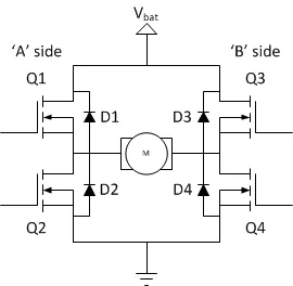
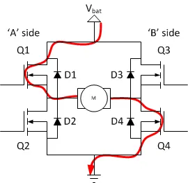
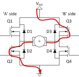
Two transistors are switched simultaneously: Q1 and Q4 or Q2 and Q3. When Q1 and Q4 are fired, a positive voltage is applied to the motor and diodes D2-D3 operate as free-wheeling diodes when Q1 and Q4 are switched off. When Q2 and Q3 are fired, a negative voltage is applied to the motor and diodes D1-D4 operate as free-wheeling diodes when Q2 and Q3 are switched off. The current flow can be seen the figure below:
Four-Quadrant Chopper (DC7):
The Four-Quadrant Chopper DC Drive (DC7) block represents a four-quadrant, DC-supplied, chopper (or DC-DC PWM converter) drive for DC motors. This drive features closed-loop speed control with four-quadrant operation. The speed control loop outputs the reference armature current of the machine. Using a PI current controller, the chopper duty cycle corresponding to the commanded armature current is derived. This duty cycle is then compared with a sawtooth carrier signal to obtain the required PWM signals for the chopper.
The main advantage of this drive, compared with other DC drives, is that it can operate in all four. In addition, due to the use of high switching frequency DC-DC converters, a lower armature current ripple (compared with thyristor-based DC drives) is obtained. However, four switching devices are required, which increases the complexity of the drive system.
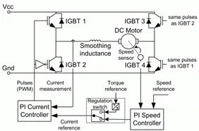
The circuit diagram and the basic operation of the four-quadrant chopper can be summarized as shown in the below figures:
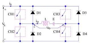
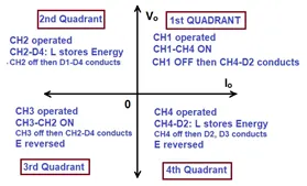
The major difference between the H-Bridge and the Four Quadrant chopper is in the quadrant operation. The Four Quadrant chopper as the name suggests, operates in all four quadrants whereas, the H-Bridge operates in only two modes viz. forward motoring and reverse motoring. This is because the current cannot flow from the load to the source (Regenerative Braking) in a H-Bridge configuration. The response of the system using the DC7 drive is more accurate owing to its added control equipment. Because of this, the DC7 chopper is more efficient.
C. To make a suitable EV model using DC7 block and make result report.
For the EV model, the reference model is taken as the DC7_example model available in the library. The 200 HP DC motor is separately excited with a constant 150 V DC field voltage source. The armature voltage is provided by an IGBT converter controlled by two PI regulators. The converter is fed by a 515 V DC voltage source. In order to limit the DC bus voltage & during dynamic braking mode, a braking chopper has been added between the Voltage source (515V) and the DC7 block.
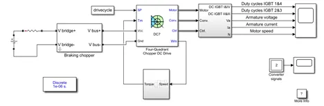
In the DC7 block, the first regulator is a speed regulator, followed by a current regulator. The speed regulator outputs the armature current reference (in p.u.) used by the current controller in order to obtain the electromagnetic torque needed to reach the desired speed. The speed reference change rate follows acceleration and deceleration ramps in order to avoid sudden reference changes that could cause armature over-current and destabilize the system. The current regulator controls the armature current by computing the appropriate duty ratios of the 5 kHz pulses of the four IGBT devices (Pulse Width Modulation).
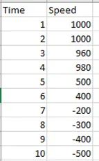
The drive cycle data is imported to the model using the from workspace block. The drive cycle data is as shown below
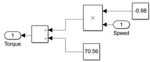
Here, the load is considered as an EV load and the torque speed equation is accordingly implemented. The torque-speed equation (referred from a previous challenge) considered is
T = -0.98ω + 70.56
The following result was obtained after simulating the model:
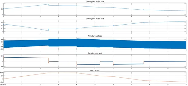
- The Duty cycle of the IGBTs can be seen varying so as to match the output voltage with the desired voltage for the obtaining the required speed.
- The duty cycle of the IGBTs 1&4 increase with increasing speed. The opposite happens in case of the IGBTs 2&3.
- Both current and voltage switch in positive and negative directions thus, the four quadrant operation of the DC7 drive can be confirmed.
- For sudden variations in speed, the drive does not have sudden fluctuations but rather has a steady response in reaching the desired speed.
CONCLUSION:
- The current overshoot can be controlled (reduced) by reducing the duty cycle and current ripples can be minimized by adding an inductor in the circuit.
- The H-bridge is a two quadrant drive whereas, the DC7 block is a four quadrant drive with better control over the response of the system.
- DC7 drive can operate in all four quadrants and supports regenerative breaking operations.