Washing Machine and Gear-shifting Using Stateflow in Simulink
AIM:
- To create an automatic Washing Machine model using Simulink
- To create a Gear Shifting model that responds to the input speed.
OBJECTIVE:
- To use chart tool to model the given examples using Stateflow available in Simulink.
- To familiarize with the dashboard blocks and give variable input to the system during the simulation run-time.
SOLUTION:
- Washing Machine
The system gets activated, if the power supply is available & if the Water supply is not available, the process should stop & indication should be given through LED
Soaking time: 200s; Washing:100s; Rinsing time: 20s; Drying time: 50s
After all the processes have completed LED should indicate ‘Finish’
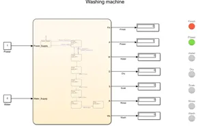
The model is created as follows:
The chart block was added in which the logic for the washing machine was implemented. This system is mostly delay-driven. The first state checks if power supply is available and then the control passes to the next block which checks for the availability of water supply. If the supply is available, the control flows to the next block. Otherwise, it flows back to the previous block and the process stops there. The next blocks are delay-driven and upon completion of one state, the variable within the state is assigned the value of 1.
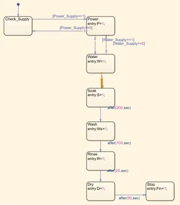
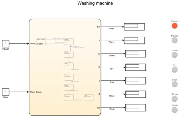
All the variables used are declared using the ‘symbol pane’ as either input(Power_Supply, Water_Supply) or output data(P,W S, Ws, R, D) as per the requirement. This output data acts as an nput to the Lamp elements that are present in the model and is also given to the display block.

The model is completed by connecting the inputs to the Stateflow model and connecting the indication lamps to their respective states by entering the ‘connect mode’. The lamps turn Green when the corresponding state is completed.
Simulation Results:
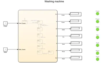
When Both power and water supply is available i.e. the constant input block is logically high, the washing machine completes the washing cycle.
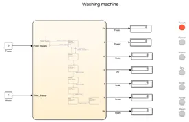
When either power or water supply is not available, the washing cycle is not completed.
- Gear Shift
It is desired the system behaves according to the following conditions:
|
Speed Range |
Gear |
|
0-15 |
1 |
|
16-25 |
2 |
|
26-40 |
3 |
|
41-60 |
4 |
|
Above 60 |
5 |
The above logic is implemented using Stateflow. This is an input-driven flow, wherein the input is variable and according to the input given, the conditions for each state is checked output is derived accordingly.
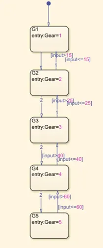
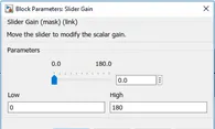
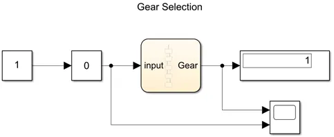
The model is completed by giving an input. It is required for the input to be variable so a Slider-Gain block is added, which enables us to change the input when the simulation is running. The slider parameters are set to a maximum value of 180kmph and minimum of 0kmph. A constant multiplier of 1 is connected to the slider gain block. The output is displayed using the display block and to visualize the changing input and output, a scope block is added.
Simulation Results:
When an input speed of 54kmph was given, the display shows 4 i.e. 4th gear since the speed lies in the range of 41-60kmph.
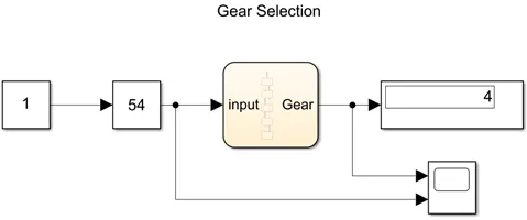
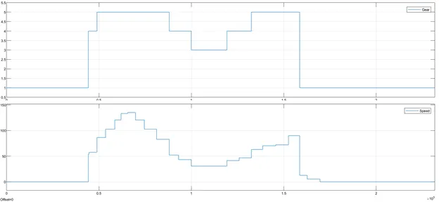
Now the simulation time is changed to infinity and the slider input is varied while the simulation is running. On observation, we can see that when speed is varied by moving the slider, the gear is shifted accordingly. For example, between 0 to 0.5*105 s, the speed changes from 0 to around 50kmph. Here the gear is accordingly changed to 4. Followed by speed of around 75kmph and 5th gear.
CONCLUSION:
- It can be concluded that Simulink can be used to model logical scenarios which are experienced in the daily life and Variable inputs can be provided during the simulation run-time.
- The Dashboard blocks help in providing the user a better representation and GUI