Week-7 Challenge: DC Motor Control
Que-1):
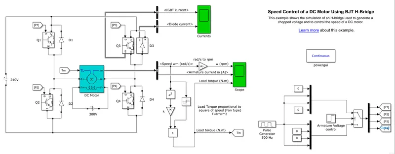
A. Explain a MATLAB demo model named ‘Speed control of a DC motor using BJT H-bridge’.
The model was download from the given link below
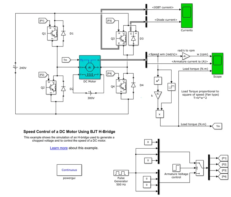
The model is given below
Explantion:
The model is designed with IGBT instered of BJT because ,the Bipolar Junction Transistor (BJT) when used for power switching applications, operates as an IGBT. When it is conducting (BJT operating in the saturated region), a forward voltage Vf is developed between collector and emitter (in the range of 1 V). Therefore, the IGBT block can be used to model the BJT device.
The IGBT block does not simulate the gate current controlling the BJT or IGBT. The switch is controlled by a Simulink® signal (1/0). The DC motor uses the preset model (5 HP 24V 1750 rpm). It simulates a fan type load (where Load torque is proportional to square of speed). The armature mean voltage can be varied from 0 to 240 V when the duty cycle (specified in the Pulse Generator block) is varied from 0 to 100%.
*Construction
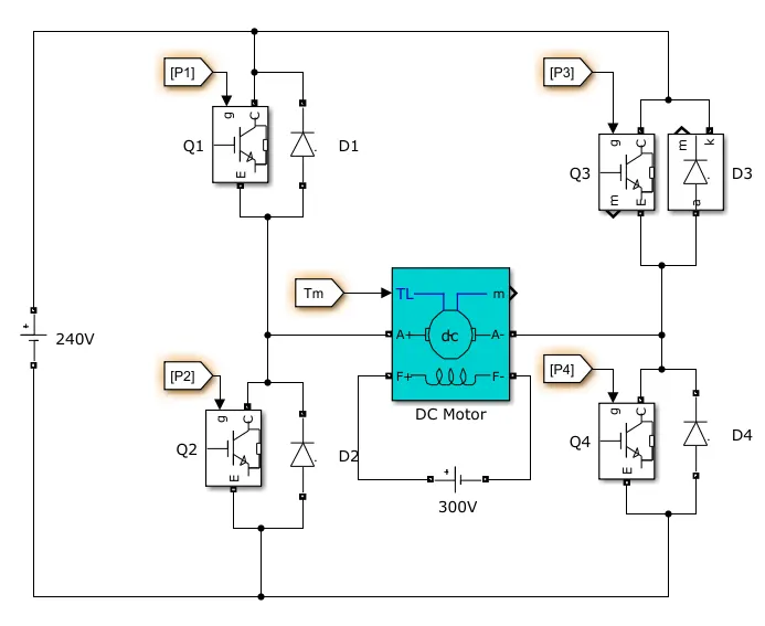
The H-bridge consists of four BJT/Diode pairs (BJT simulated by IGBT models). The 2 pairs (BJT/diode) are connected in series, which results in 2 pairs with 2 BJT sects. The 2 series pairs are connected in parallel to each other.
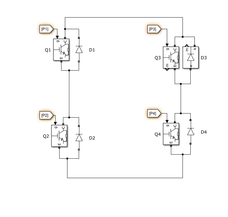
Q1Q3 are connected to the positive supply and Q2Q4 are connected to the negitive supply of the Battery.Q1Q2 are connected to the positive supply and Q3Q4 are connected to the negitive supply of the Motor.
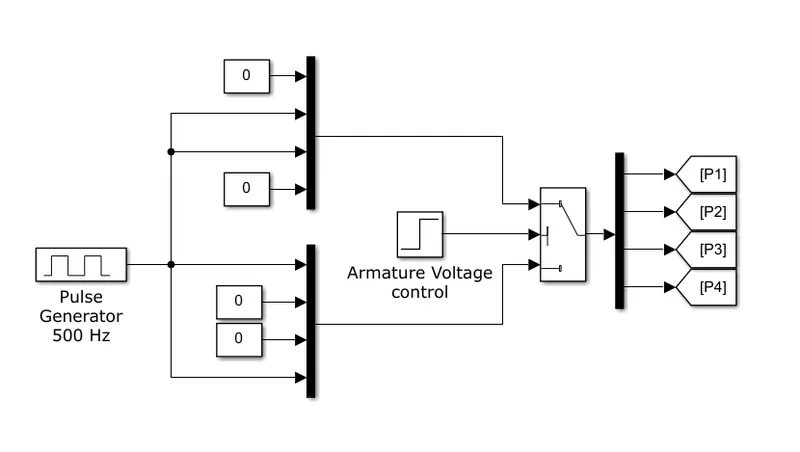
Controll Signal for the BJT's are generated by the Puls generater. Two sets are created to run the motor in Both directions
Model file:
All other are details are shown in the simulation file
Working:
Two transistors are switched simultaneously: Q1 and Q4 or Q2 and Q3. When Q1 and Q4 are fired, a positive voltage is applied to the motor and diodes D2-D3 operate as free-wheeling diodes.
when Q1 and Q4 are switched off. When Q2 and Q3 are fired, a negative voltage is applied to the motor and diodes D1-D4 operate as free-wheeling diodes when Q2 and Q3 are switched off.
As the volatge across the motor is reversed, the direction of rotation also reversed.
To show the both direction of roations, in control signal was designed to run motor in half sec for one direction i.e, Q1 and Q4 are turned ON and Q2 and Q3 are turned OFF and another half sec for other direction i.e., Q2 and Q3 are turned ON and Q1 and Q4 are turned OFF.
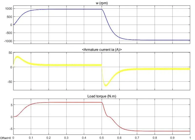
The motor starts in the positive direction with a duty cycle of 75% (mean DC voltage of 180V). At t= 0.5 sec., the armature voltage is suddenly reversed and the motor runs in the negative direction.
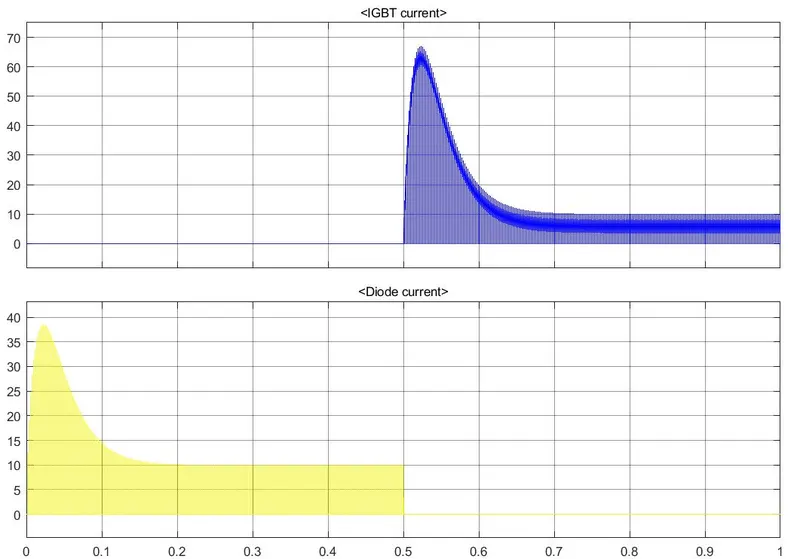
'Scope' shows motor speed, armature current and load torque and 'Currents' shows currents flowing in BJT Q3 and diode D3.
Scope Results
First half second the motor rotaes in positive direction, the speed starts from zero and reaches to the max speed gradually in 0.15 sec and maintainded constant speed, in that sitivation Q1 and Q4 are turned ON. The spick in Armature current in starting beacuse as there is no Back EMF in starting ,the Current will be high. As the speed pics up the Back EMF also increses so the Current also decreses. This also applicable to negitive speed also. As the Spwwd changes the torque as changes as T = K*W^2.So the Torque follows the Speed.
The results are shown below are the BJT (Q3). In first Half sec the Q3 is OFF so the current is also zero,but the Diode carries the Circulating currents. In next Half sec the Q3 is On so the Load current passes through it. The circulating currents will not flow throug Diode D3 so it shows zero.
B. Comment on the armature current shoot-up from the scope results.
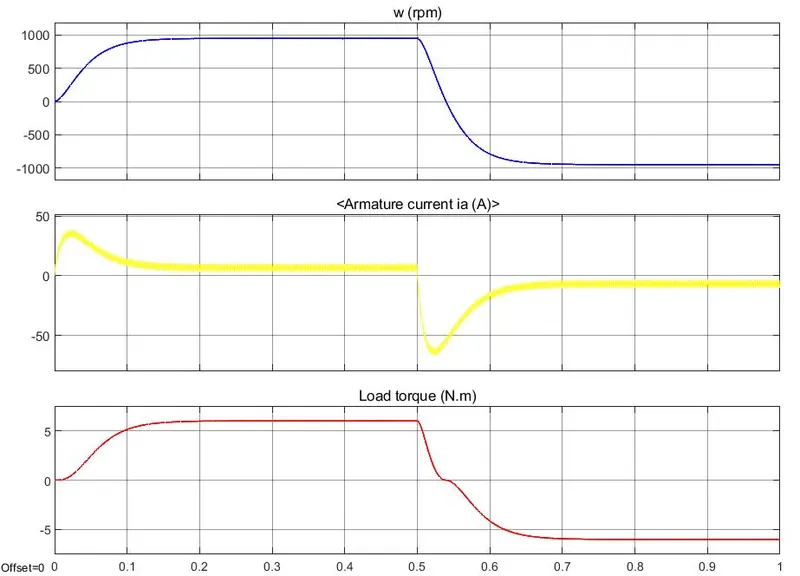
The shoot of the armature current is there in starting only i.e., when the motor reaches from zero to max speed. Beacuse we know that Back EMF is directly praportional to the Speed of the motor and V = Eb + Ia*Ra => Ia = (V-Eb)/Ra .If the Eb is less the Ia is high. In starting the motor is in rest position when the supply is given the motor starts running from zero to max speed gradually, it will not reach max speed instant it takes some time to reach max speed. As speed is praportion to Eb, Eb also increases gradually from Zero. So at starting the Eb is 0 the Current is High . In otherwords at starting there is no opposing froce i.e Eb to current so high inrush current will flow into the motor. When the motor reaches to max speed the Eb is also Max the current is limited. In practical cases the high in ush currents will damage the motor so startes are used to limit the staring inrush currents to protect the motor.
C. Refer to the help section of ‘The Four-Quadrant Chopper DC Drive (DC7) block’. Compare it with the H-bridge model.
Note: Comparing only the Blocks i.e., DC7 and H-Bridge and not the total Model
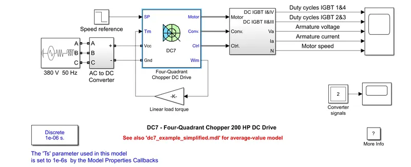
The Four-Quadrant Chopper DC Drive (DC7) block:
Speed control of a DC motor using BJT H-bridge:
| The Four-Quadrant Chopper DC Drive (DC7) block |
H-bridge model. |
|
It can control the motor in all four quadrant i.e., Q1 -Forward Motoring Q2 - Forward Braking Q3 - Reverse Motoring Q4 - Reverse Braking |
It can operate only in 2 quadrant i.e., Q1 -Forward Motoring Q3 - Reverse Motoring |
| Speed is controlled by Refeance speed and Duty cycle is changed according to it. | We need to change the duty cycle according to the speed requried in Puls Generator Block |
| The supply is given with 3-phase AC and then converted to DC with Rectifier. | The supply is given by direct DC supply |
| It uses IGBT as switching device | It uses IGBT as switching device |
| The speed has a referance so that motor will run at the referance speed. | It doesnot have any speed referance, the speed is depend on the motor values and supply voltage. |
Que-2)
Develop a 2-quadrant chopper using simulink & explain the working of the same with the relevant results.
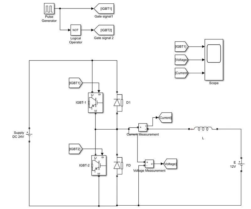
Simulation model;
OUTPUT:
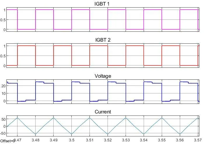
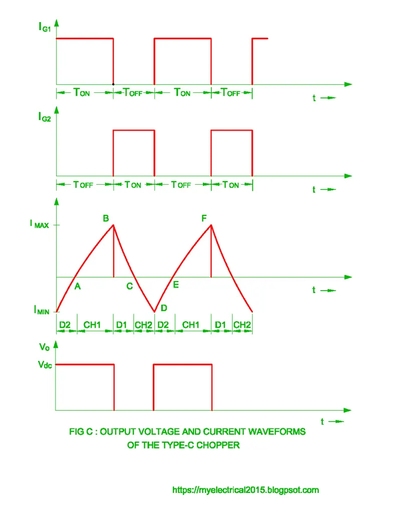
When IGBT 1 is ON and IGBT 2 if OFF the volage is in positive i.e., 24v and the current is Positive i.e., 50A and when the IGBT 1 is OFF and IGBT 2 is ON The Voltage is Positive and the current is Negitive i.e., -50A
Working:
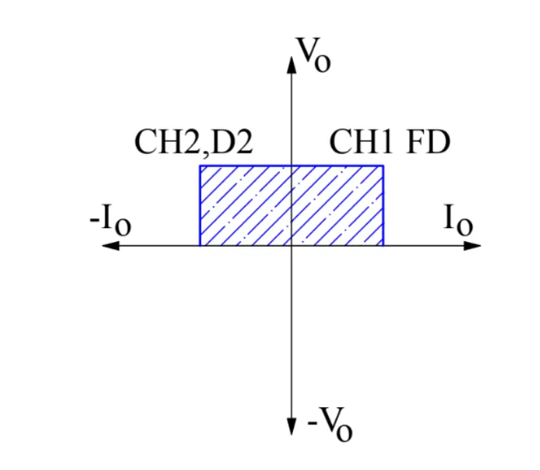
This is a Type-C chopper, which is a combination of Type-A and Type-B chopper. Type-A chopper is a 1st Quadratent chopper i.e., both Volatge and Current are Positive. Type-B chopper is a 2nd Quadratent chopper i.e., Volatge is positive and Current is Negitive. As Type-C chopper is a combination og Type-A and Type-B i.e., it opeartes in both 1st and 2nd Quadratents. The voltage is positive and the current will be positive and negitive that depends on the Switches.
The circuit is made with 2 IGBT's ,1 diodes , 1 Freewealing diode,Inductor L with 1e-3 H ,Voltage source as 12V and Supply source as 24V. For gate triggerig the pulse generator is used.Both the IGBT's shold not turn ON simultaniously,because it will short circuit the Supply. So the logic is when the IGBT 1 is ON IGBT 2 should be OFF and vice versa. To acchive that the NOT logic is used in the design.The pulse width is 0.02 and duty cycle is 50% so that for every pulse half time IGBT 1 is ON and anoth half time IGBT 2 is ON. This refers to the Quadratent-1 Forword motor mode. The Current measurnment and Voltage MEasurnment are used to mesure the load current and voltage.
When the IGBT 1 is ON state and IGBT 2 will be in OFF state. So the supply goes from the Supply source +ve to IGBT 1 to Inductor to E to supply source -ve.IN this process the Inductor will store energy This showes that the Voltage is +ve and current as +ve , that can be observed by the OUTPUT graph.When the IGBT 1 and 2 are OFF, the energy stored in the Inductor will goes through Inductor to E to FD to Inductor. In this case also the load voltage and current are +ve. When IGBT 1 is ON the current is increasing and when it is OFF the Cureent is decreased through Diode FD
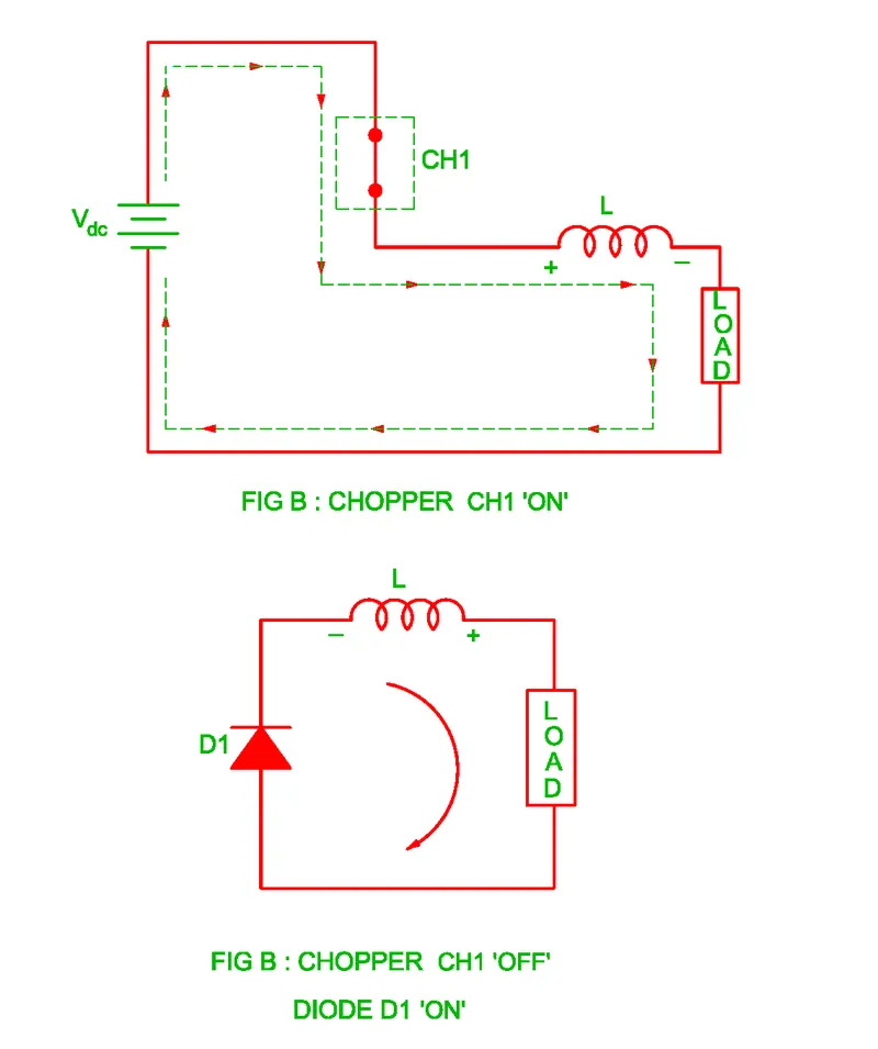
When the IGBT 1 is OFF state and IGBT 2 will be in ON state. Load DC source E drives current through CH2 and load i.e., E +ve to L to IGBT 2 to E -ve. In that case the Voltage is +ve same as before but current diretction is changed to opposite i.e., current is -ve. The IGBT 2 also OFF state than supply is E +ve to L to D1 to Supply +ve to E -ve. The voltage is +ve and the current -ve. This refers to the Quadratent-2 Forword braking mode.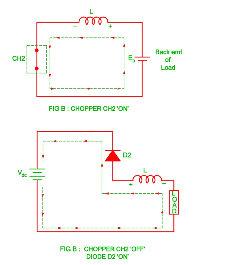
Que-3)
3. Explain in a brief about operation of BLDC motor
is a permanent magnet synchronous electric motor which is driven by direct current (DC) electricity and it accomplishes electronically controlled commutation system (commutation is the process of producing rotational torque in the motor by changing phase currents through it at appropriate times) instead of a mechanically commutation system. BLDC motors are also referred as trapezoidal permanent magnet motors.
The armature coils are switched electronically by transistors or SCR at the correct rotor position in such a way that armature field is in space quadrature with the rotor field poles. Hence the force acting on the rotor causes it to rotate. Hall sensors or rotary encoders are most commonly used to sense the position of the rotor and are positioned around the stator. The rotor position feedback from the sensor helps to determine when to switch the armature current.
This electronic commutation arrangement eliminates the commutator arrangement and brushes in a DC motor and hence more reliable and less noisy operation is achieved. Due to the absence of brushes BLDC motors are capable to run at high speeds. The efficiency of BLDC motors is typically 85 to 90 percent, whereas as brushed type DC motors are 75 to 80 percent efficient. There are wide varieties of BLDC motors available ranging from small power range to fractional horsepower, integral horsepower and large power ranges.
Consider the figure below in which motor stator is excited based on different switching states. With the switching of windings as High and Low signals, corresponding winding energized as North and South poles. The permanent magnet rotor with North and South poles align with stator poles causing motor to rotate.
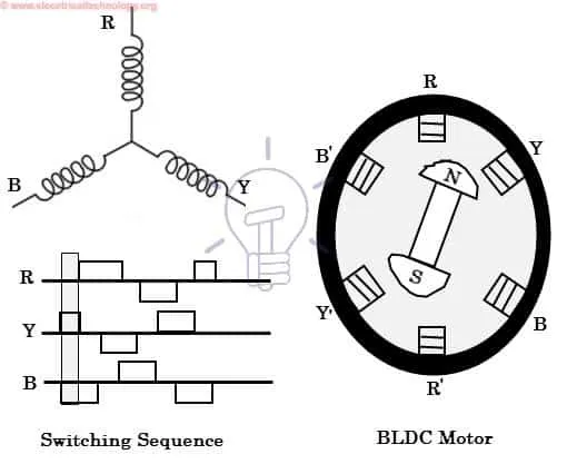
Let us assume that the Stator has the 3 pairs of poles with each pair of poles are connected to different phases. The rotor is of 2 pole i.e., North and South. Let us concidered the no stator poles are energised and rotor is between the R and Y to rotate the rotor in cloclwise direction the Y is energied, Y pole will from South and Y' will form North due to accration force the rotor will rotate Clockwise direction. at the same time to increase the Efficiency the preseding poles i.e., R and R' are also energised sin such a way that the R as North and R' South so due to Replusion froce between the Rotor poles and stator poles the rotor rotates in clock wise direction. Now the rotor will allin with the Stator Y phase at that instant the Y and R phases are deenergised and next phase in clockwise i.e., B phase is energised in such a way taht it attracts the rotor and at the same time the presiding pole i.e., Y is also energised in such a way that it reples the rotor. In this way step by step the poles are energised and de energised to run the motor. If we want run the motor in anticlock wise direction the energising sequence should be rebversed . To know the exact Postion of the rotor in order to choose which poles should be Energised and what should be the current direction. For that Rotor position sensors are used.The speed of the motor is controlled by switching speed of the switches.
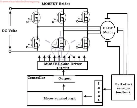
The Switching and Supply connections are shown in below figure.Each phase is connected with 2 switches across the swiches the supply is connected as shown in figure. Upper switches are used for +ve direction of current to phases i.e., poles and lower switches are used for -ve direction of current.The Switching sequence is controlled by the controlles which takes speed and position of rotor as feedback.
Observe that motor produces torque because of the development of attraction forces (when North-South or South-North alignment) and repulsion forces (when North-North or South-South alignment). By this way motor moves in a clockwise direction.
For more information refere to the below link: