Week-7 Challenge: DC Motor Control
1. A. Explain a MATLAB demo model named ‘Speed control of a DC motor using BJT H-bridge.
H-BRIDGE:
An H-bridge is an electronic circuit that switches the polarity of a voltage applied to a load. These circuits are often used in robotics and other applications to allow DC motors to run forwards or backwards.
Introduction to DC Motor:
DC means Direct Current and due to the pre-existing power distribution system, these motors could easily be controlled. The current flow in the wiring controls the speed of the motor. It has a direct relationship.
A DC motor is a device or machine that converts DC power into mechanical energy. Its operation follows the principle that when a conductor carrying current is placed in a magnetic field the conductor experiences a mechanical force. Fleming’s left-hand rule gives the direction of force.
Open the MATLAB document and search for "Speed control of a DC motor using BJT H-bridge"
The result tab open, select the model and click open.
Refer to the help section of ‘The Four-Quadrant Chopper DC Drive (DC7) block’. Compare it with the H-bridge model:
The Four-Quadrant Chopper DC Drive:
A Four-Quadrant Chopper (or Four-Quadrant DC Drive) is a DC drive configuration that allows control of a DC motor in all four quadrants of the speed-torque plane. This configuration is essential in applications where bidirectional speed control and regenerative braking are required, making it highly relevant for electric vehicles industrial applications and robotics.
Quadrants of Operation:
First Quadrant (Forward Motoring):
The motor runs in the forward direction with a positive speed and torque.
The chopper acts as a step-down converter, supplying the motor with positive voltage and current.
This quadrant is typical for driving the vehicle or system forward.
Second Quadrant (Forward Braking):
The motor continues to run in the forward direction, but torque is reversed to provide braking.
The chopper allows regenerative braking, where energy flows back to the source like a battery.
This is useful for slowing down the vehicle while recovering energy.
Third Quadrant (Reverse Motoring):
The motor runs in reverse, with both speed and torque being negative.
The chopper supplies negative voltage and current to drive the motor in the reverse direction.
This quadrant is typically used for driving the vehicle backward.
Fourth Quadrant (Reverse Braking):
The motor still runs in reverse, but torque is positive, meaning it brakes while moving backward.
Similar to the second quadrant, regenerative braking can be used here to recover energy.
This quadrant is used to slow down the vehicle during reverse motion.
The current values are continuous in BJT and In Four Quadrants it is chopped so that the simulation takes less time. To change the direction of the motor current signals are interrupted in four quadrants. Whereas in BJT the polarity of the current needs to be changed.
The main advantage of Four quadrant is that it operates in all the four quadrants but BJT can movie only is two directions. Four Quadrants provides better efficiency and operates at high power levels when compared to BJT that operates at moderate power levels.
2. Develop a 2-quadrant chopper using Simulink & explain the working of the same with the relevant results. (Refer to article – Multi quadrant operation of motor ):
A 2-Quadrant Chopper also known as a two-quadrant DC-DC converter is a type of DC chopper that enables control over the direction of current but maintains a fixed polarity for the voltage applied to the load. This allows the system to operate in two distinct quadrants of the torque-speed plane.
First Quadrant:
Forward motoring positive speed and positive torque.
Second Quadrant:
Forward braking positive speed but negative torque, enabling regenerative braking.
This type of chopper is particularly useful in applications where bidirectional current is needed but without reversing the motor's direction.
3. Explain in a brief about operation of BLDC motor:
Brushless DC motors BLDC are widely used in various applications such as robotics electric vehicles drones and industrial automation systems. Unlike conventional DC motors, BLDC motors do not have brushes which makes them more reliable and efficient. Brushless DC motors are also known as electronically commutated motors ECMs EC motors.
BLDC motor is a permanent magnet synchronous electric motor which is driven by direct current (DC) electricity and it accomplishes electronically controlled commutation system commutation is the process of producing rotational torque in the motor by changing phase currents through it at appropriate times instead of a mechanically commutation system. BLDC motors are also referred to as trapezoidal permanent magnet motors.
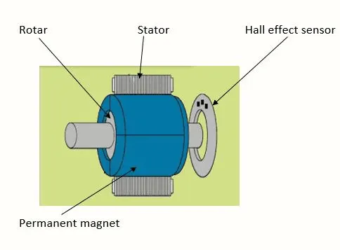
BLDC Motor Components and Construction:
A BLDC motor has three main components are stator the rotor and the Hall effect Sensor.
Stator:
The stator is the stationary part of the motor that contains the windings. These windings are made up of insulated copper wire and are arranged in a specific pattern. The stator provides a magnetic field that interacts with the rotor to produce torque.
Rotor:
The rotor is the rotating part of the motor that contains permanent magnets. The magnets are arranged in a specific pattern, opposite to that of the stator. The interaction between the magnetic fields of the stator and the rotor produces rotational movement.
Hall effect Sensor or Electronic controller:
The Hall effect Sensor is the brain of the motor. It is responsible for controlling the flow of current to the motor windings. The controller also senses the position of the rotor and adjusts the current accordingly to ensure smooth and efficient operation.
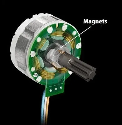
Working Principle of BLDC Motor:
The working principle of BLDC motors is based on the interaction between the magnetic fields of the stator and the rotor. The stator produces a rotating magnetic field which interacts with the permanent magnets on the rotor producing a torque that causes the rotor to rotate.
The Hall Effect Sensor plays a crucial role in the operation of the motor. It controls the flow of current to the motor windings based on the position of the rotor. The controller senses the position of the rotor using sensors or Hall effect devices mounted on the stator. These sensors detect the position of the magnets on the rotor and send signals to the controller.
Based on the signals from the sensors, the controller adjusts the flow of current to the motor windings to ensure that the magnetic fields of the stator and rotor are properly aligned. This ensures that the motor operates efficiently and smoothly, without any loss of power or vibration.
Advantages of BLDC Motors:
Higher efficiency:
BLDC motors are more efficient than conventional DC motors due to the absence of brushes. This results in less friction and lower power loss.
Higher power density:
BLDC motors have a higher power density compared to conventional DC motors. This means that they can produce more power in a smaller size.
Longer lifespan:
The absence of brushes in BLDC motors results in less wear and tear, making them more reliable and durable.
Low maintenance:
BLDC motors require less maintenance compared to conventional DC motors. This results in lower maintenance costs and longer service life.
Applications of Brushless DC motor:
Computer hard drives and DVD/CD players
Electric vehicles hybrid vehicles and electric bicycles
Industrial robots CNC machine tools and simple belt driven systems
Washing machines compressors and dryers
Fans pumps and blowers.