Project 1
1. Design a battery pack for a car roughly 150 Kw with 120 V. Use 3500 mAh 3.6V nominal NMC chemistry cell.
a. Design the battery pack configuration.
b. Draw the BMS topology for this battery pack.
Given Data:
Required Power = 150 Kw
Required Voltage = 120 V
Battery Capacity = 3500 mAh = 3.5 mAh
Nominal Voltage = 3.6 V
Solution:
1. Find the total no. of cells connect in series and parallel
Find the current value:
P = v* I
I = P/v
= 120 / 3.6 = 1250 A.
Find the No. of cells connect in series:
No. of cell = Required Voltage / Nominal voltage
No. of cell = 120 / 3.6 = 33.33 * (we will round cell for 34 cells in series)
Find the no. of cells connect in parallel:
No. of cell in parallel = Total Current / Total Cell nominal Capacity
No. of cell in parallel = 1250 / 3.5 = 357.14 * (358 cells in parallel of round off)
Find the Nominal voltage of the battery:
Nominal voltage = 34 * 3.6 = 122.4 V
2. Draw the BMS topology for this battery pack.
BMS Topology:
BMS – Battery Management System
Depending on the applications, there are different types of BMS Hardware topologies. That can be applied for the achieving the design objective of the battery packs.
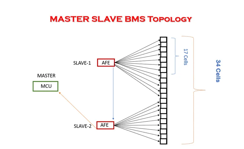
BMS topology based on number of cells connected in series so the number of cells is 34 cells so the cells are more than 18 then we use master and slave topology.
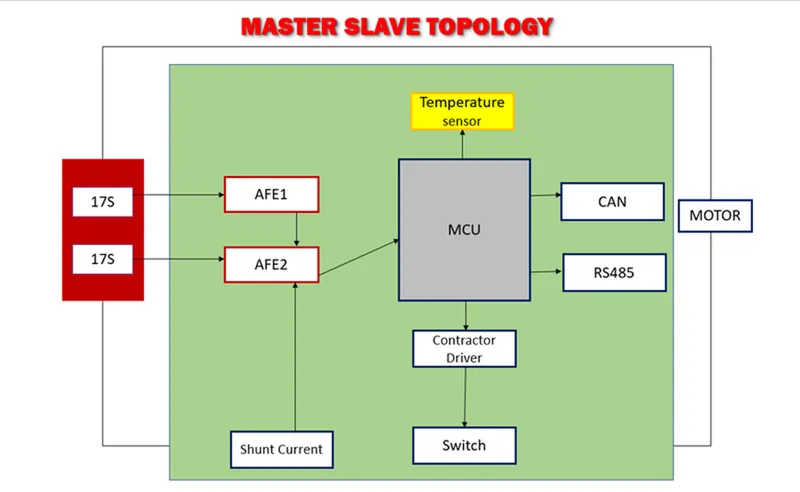
In this topology we using daisy chain interface means it collects the all data of slave-1 is sent to slave-2 collects the 17 cells data and the slave-2 and slave-1 data sent to micro controller unit.
2.Build a 3S2P battery pack configuration with generic battery block using MATLAB/Simulink.
Aim:
Design the Build a 3S2P battery pack configuration with generic battery block using MATLAB/Simulink.
Solution:
The battery cell 3 connect in series and 2 connect in parallel.
Total no of cells = 3*2 = 6 cells
Model Explanation:
Power Gui:
It is used to store the equivalent Simulink circuit that represents the state-space equations of Specialised Power System blocks.
Constant:
The Constant block generates a real or complex constant value signal. Use this block to provide a constant signal input.
Bus Selector:
The Bus Selector block extracts the elements you select by name from the input bus hierarchy. The block can output the selected elements separately or in a new virtual bus.
Battery:
This block can be made use to analyze charge and discharge characteristics and SOC temperature effects and age equivalent of the battery system.
Voltage Measurement Block:
The Voltage Measurement block measures the instantaneous voltage between two electric nodes.
Scope:
The Scope allows you to adjust the amount of time and the range of input values displayed. You can move and resize the Scope window and you can modify the Scope parameter values during the simulation.
Controlled Current Source:
The Controlled Current Source block converts the Simulink input signal into an equivalent current source. The generated current is driven by the input signal of the block.
Display:
The Display block connects to a signal in your model and displays its value during simulation. You can configure the appearance and format of the Display block to make intuitive sense for the value it displays.
Open MATLAB and type Simulink in command window and type enter. The Simulink start page will be open then click the start model it will open the new untitled model.
The untitled page clicks the library browser the blocks in the browser. go to search box and search power Gui block and drag to the model page. Same procedure for all blocks.
The battery block takes 6 blocks in the library browser then double click the block set the rated capacity and nominal voltage. The nominal voltage is 3.6 and rated capacity is 3.5. Same process for all battery blocks.
The parallel connection batteries are connected from terminals to same terminals of other batteries that is positive terminal (+) of one battery is connected with positive (+) terminal of other battery and negative terminal (-) of one battery with negative terminal (-) of other battery.
the battery connected in series and parallel
combination. Batteries are connected from terminal to
terminal in a way that the positive (+) terminal of one battery is connected
with the negative (-) terminal of the other battery and negative terminal (-)
of one battery is connected with the positive terminal (+) of the other
battery.
The voltage measurement block is connected across the battery pack to measure the battery pack voltage. The scope output used for the battery pack consists of SOC (State of Charge), Current and voltage. The controlled current signal is given as the load to the battery pack. The constant block is determined with battery capacity and it is given to the controlled current block.
The parameter is:
Nominal voltage of a cell 3.6 V
Rated capacity of a cell 3.5 Ah
Maximum voltage of a cell 4.1V
Nominal voltage of the battery pack = no. of cell in series * nominal voltage of a cell
= 3*3.6 = 10.8 V
Rated capacity of the battery pack = no. of cell in parallel* rated capacity of a cell
= 2*3.5 = 7 Ah
Over All Voltage of Battery Pack = maximum voltage of the battery * no. of cells in series
= 4.2*3 = 12.6 V
Over All Voltage = 12.6 V.