Week-7 Challenge: DC Motor Control
Challenge01:
A). Explain a MATLAB demo model named ‘Speed control of a DC motor using BJT H-bridge’.
- In this model Speed control of Separately excited DC motor is achieved by using BJT as a switch, instead of BJT an IGBT is used because when used for Power switching BJT operates same as IGBT.
- The circuit basic operation of control circuit can be understand from an image given below.
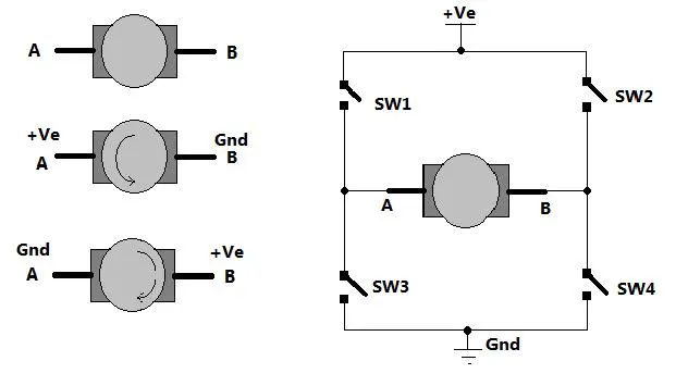
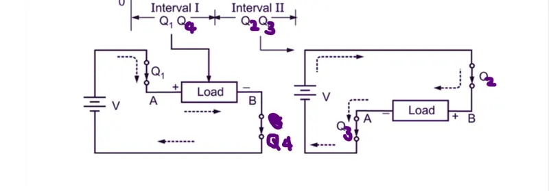
- There are four switches connected across motor, When SW1 and SW4 are given control signal both switches get closed and the current flow path is from +ve >SW1> A terminal >B terminal >SW4 > GND. Motor is rotating in Forward direction.
- When control signal are given to SW2 and SW3 simultaneously the current flow through motor get reversed that is +ve>SW2>B terminal>A terminal> SW3>GND, Motor is rotating in reversed direction now.
- Let's come to circuit,there we can see an anti-parallel diode is connected across each Switch that is because Motor is a RLE load and we know that inductor does not allow sudden change in current flow, so whenever a switch get turned off, there is large negative voltage appears across it due to the effect of inductor stored energy and to freewheel that energy and fedback to source can be done by diodes.
- Also IGBT is a unidirectional device hence it has no reverse conduction and has very weak reverse blocking capability so to prevent it , feedback diodes are connected in anti-parallel manner.
- Now, We will understand the operation of actual model.
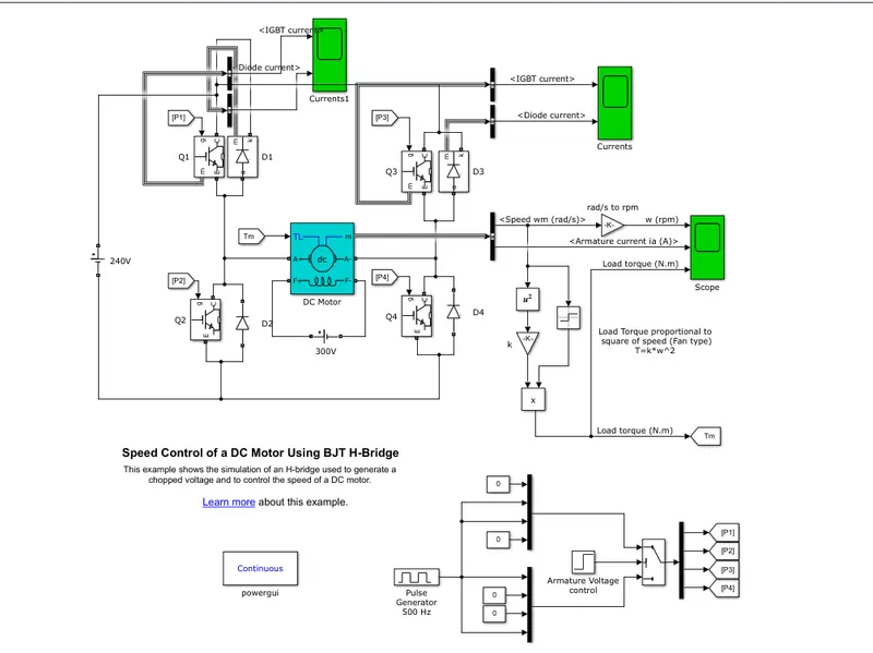
- Speed control is done by switching operation of IGBT, when a positive pulse is given to IGBT gate terminal, it got triggered and there is flow of current from Collector to Emitter termina.
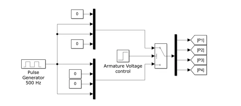
- The gate signal is given to each IGBT from the arrangement shown just above.
- A pulse generator block with Amplitude of 1 and frequency of 500 Hz with 75% duty cycle is generating continouos pulses.
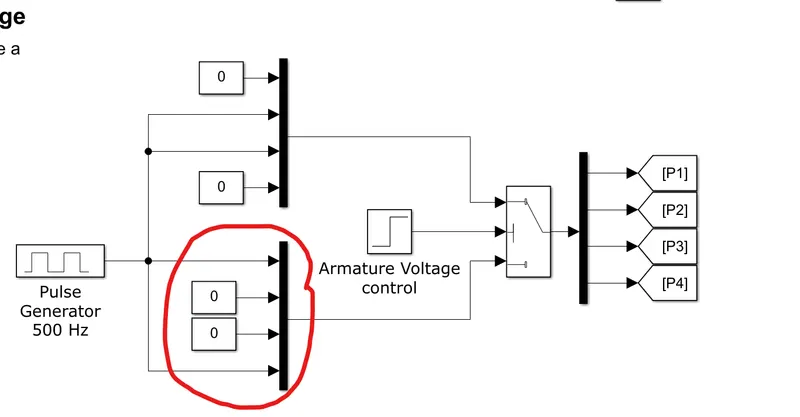
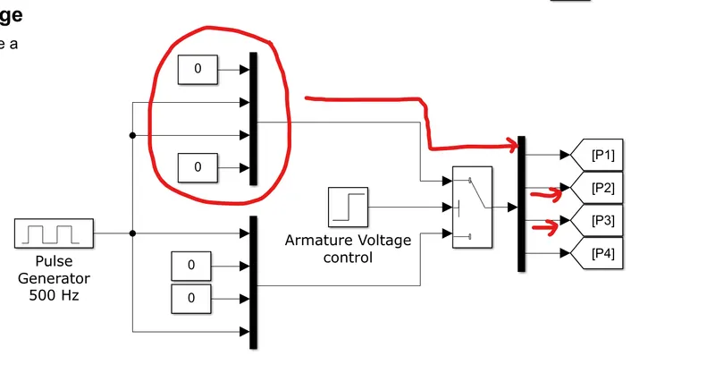
- These pulses are given to two Mux with 4 inputs as shown, Upper Mux has 1st and 4th input as zero but 2nd and 3rd input as generated pulse.
- Similarly, the lower Mux has complementary arrangement of upper Mux with 1st and 4th input as generated pulse and 2nd, 3rd input as zero.
- Output from Both Mux is then given to the switch block and the switch is controlled by Armature Voltage which is a step signal as shown below.
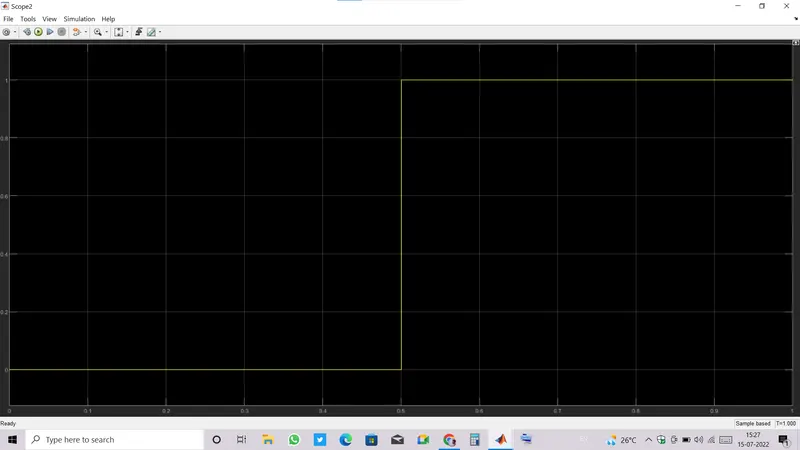
- Switch threshold is set to 0.5, it means when the value greater than switch threshold appear the switch output will be taken from Upper port and whenever value lesser than switch threshold appear the switch output will be taken from lower port.
- Till 0.5 sec the armature voltage control signal has value 0 which is less than threshold so that the Switch output will be taken from Lower port which is going to be P1 and P4 as P2 and P3 are zero.
- Similarly, from 0.5 to 1 sec the armature voltage control signal has value 1 which is greater than threshold so that the Switch output will be taken from upper port which is going to be P2 and P3 as P1 and P4 are zero.
- So the gate signal for switch Q1 and Q4 are given first till 0.5 secs which frequently turns on and off the switch Q1 and Q4 and the output voltage(which appears across armature of motor) can be calculated by an equation : Vdc = Vs. (ton/ T), Where T = ton+toff.
- Vdc will be 0.75*240 = 180 V till Q1 and Q4 operated.
- The flow of current will be: Vs > Q1 >Motor > Q4 >Vs.
- The magnitude of current is decided by Vdc ,Back Emf and Ra where Vdc and Ra are constant Back Emf varies according to speed.
- Mathematical equation of armature current will be : Ia = (Vdc - Eb)/Ra
- Back emf is an emf induced in conductor under the effect of stator magnetic field which opposes applied voltage.
- When Q1 and Q4 turned off there is still current flowing in circuit due to the effect of inductor present in motor,now the terminals are isolated from supply but the energy stored in inductor needs to be dissipated and this can be done through Feedback diodes , the diode D2 and D3 are now turned on and feedback energy to Source.
- After 0.5 sec to 1sec, Gate signals fro Q2 and Q3 are given.
- Now, the direction of current get reversed which result in rotation of motor in reverse direction.
- The flow of current will be: Vs > Q2 >Motor > Q3 > Vs.
- At this time back emf starts supporting supply voltage hence the current will be : Ia = (Vdc + Eb)/Ra , which is greater than previous case.
- When Q2 and Q3 turned off there is still current flowing in circuit due to the effect of inductor present in motor,now the terminals are isolated from supply but the energy stored in inductor needs to be dissipated and this can be done through Feedback diodes , this time diode D1 and D4 are turned on and feedback energy to Source.
RESULTS:
- Current flowing in motor forward operation is from Q1 and Q4 during Q1,Q4 on condition and from D2 and D3 during Q1,Q4 off condition will be same and the magnitude is current will be Ia = (Vdc - Eb)/Ra = 38 Ampere Max. (observed from scope).
- At the starting, current is rising rapidly because there is no Back emf.
- After sometime when back emf starts building , we can see current is falling and finally settled to a constant value (Ia = (Vdc - Eb)/Ra).
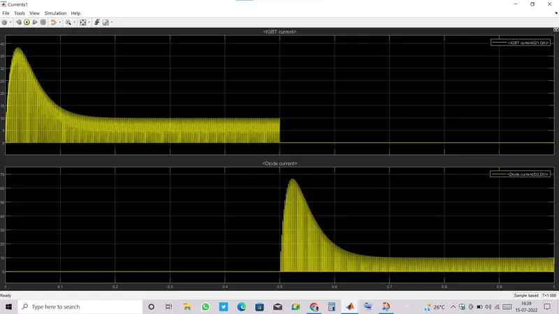
- And the current flowing in motor reversed operation is from Q2 and Q3 during Q2,Q3 on condition and from D1 and D4 during Q2,Q3 off condition will be same and the magnitude is current will be Ia = (Vdc + Eb)/Ra = 67 Ampere Max. (observed from scope).
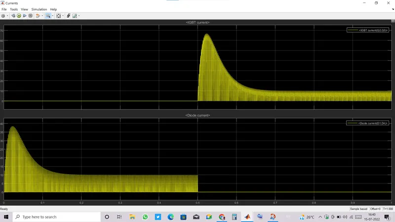
- In forward motoring current is less than reversed motoring current because of back emf, Back emf oppposed in forward motoring and in reversed motoring mode back emf supported current flow for some instance.
- When Current flowing through motor was from +A to -A the current is considered as positive hence the rotation is in forward direction and when current flowing through motor was from -A to +A , it is considered as negative current which in turn result in reversed rotation of motor.
- The ripples in armature current is due to the switching action of IGBT and diode.
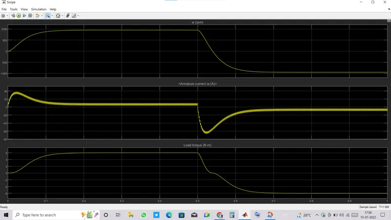
- Load torque is increasing as motor is gaining speed(Tl = K.w^2).
- When there is no differerence in motor torque and load torque the motor atttains steady state speed hence no further acceleration.
- Till 0.15 secs motor is accelerating after that motor is running at a constant speed nearly 950 RPM.
- When the direction of current got reversed, the motor torque direction also got reversed hence there is decelaration from 0.5 sec to 0.55 sec and then motor started rotating in reversed direction.
- The motor speed is accelerating in reversed direction till the load torque and motor torque difference becomes zero.After that motor againg attains a constant speed.
- Deceleration is faster because of large current in reversed direction result in large motor torque.
B). Comment on the armature current shoot-up from the scope results.
- The shoot up in armature current is because of absence of Back emf at the starting of motor, as motor is gaining speed and back emf start building the current is falling down till motor speed becomes constant.
- Ia = (Vdc - Eb)/Ra, Ra is very small.
- When motor is at rest, Eb = 0 ,hence result in shooting current.
- Motor gaining speed result in rise in Eb hence Ia start falling till speed becomes constant.
C). Comparison between The Four-Quadrant Chopper DC Drive (DC7) block and H-Bridge model:
- In four quadrant chopper DC drive, All four quadrant motor operation(forward motoring, forward braking,reverse motoring ,reverse braking) can be achieved by Chopper four quadrant operation.
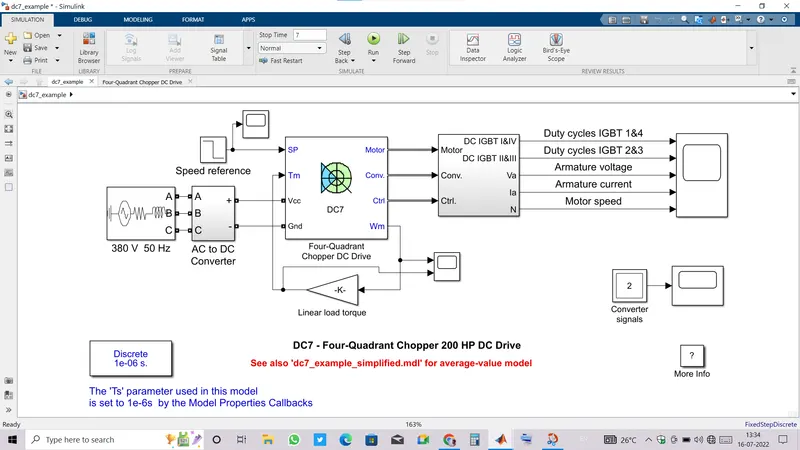
- In model, AC supply is converted to DC by AC to DC converter and DC voltage is then given to Four-quadrant chopper.
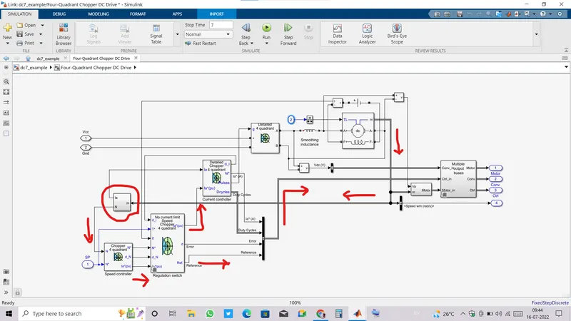
- Let's get into Four-Quadrant chopper DC drive arrangement.
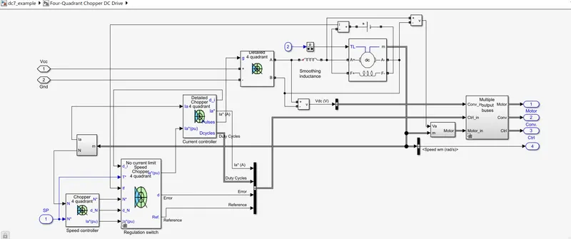
- Voltage Vcc and Ground are main input to chopper , gate signal to tigger IGBT is given from the Current controller.
- Actual armature current and speed are taken from motor data and then compared with reference Speed and current, in Speed contoller circuit ,the difference is called as error which is then given to the Regulation switch which is sending current reference to Current controller and the error and reference signal to controller input.
- Inside Current controller , the Error between actual and reference current is minimized by using Propotional and integral control.
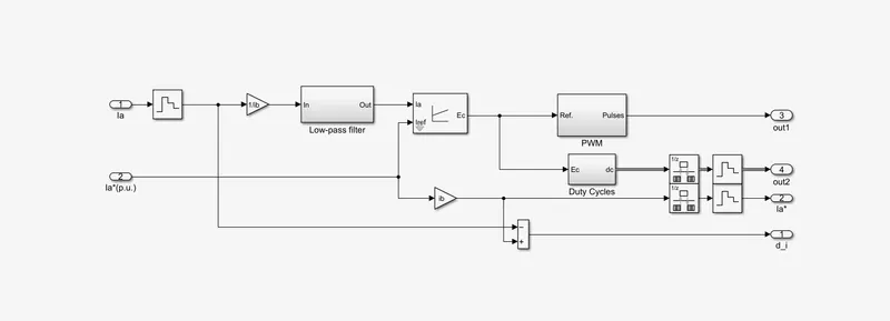
- Error signal is minimized and duty cycle of IGBTs are calculated fron this error signal so that the pulse width of gate signal can be decided in order to match reference value.
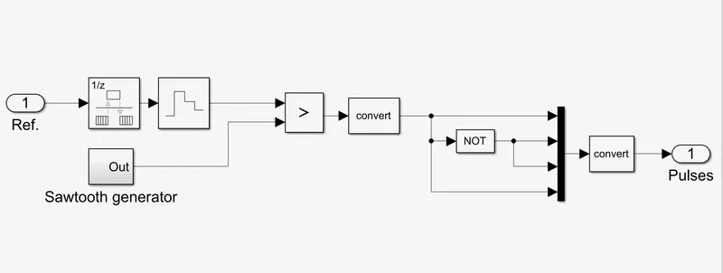
- The gate pulse for each four IGBT are given through this error signal, this error signal is compared with Sawtooth generator wave , if error magnitude is found more than sawtooth wave magnitude the IGBT 1 and 4 are triggered to match reference value and if eror magnitude is found less than sawtooth wave magnitude IGBT 2 and 3 got firing signal.
RESULT:
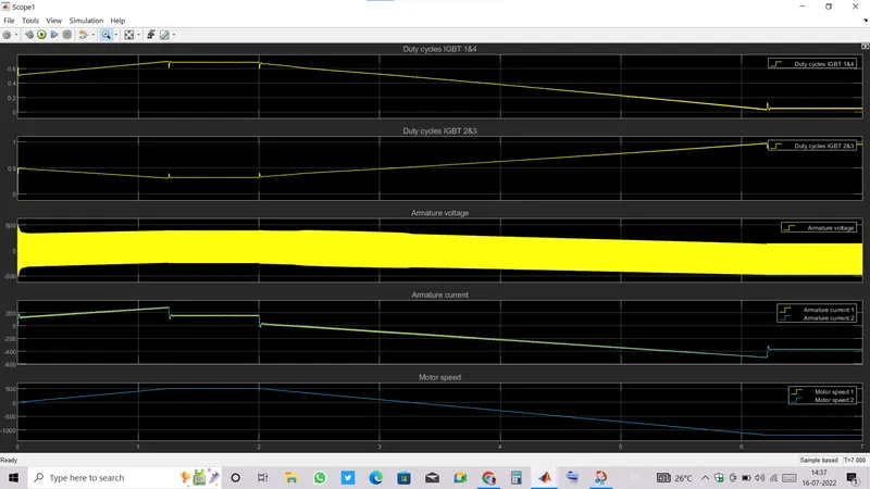
- From starting to 1.2 sec the IGBT 1 and 4 are getting large duty cycle than IGBT 2 and 3 hence the average voltage across armature is positive and which result in motor to run in forward direction. The current and voltage can be seen postive during forward motoring mode.
- Current is increasing and motoring is also gaining speed till 1.2 secs.
- After 1.2 sec to 2 secs , armature current becomes constant and motor speed is also.
- From 2 secs motor comes into Forward braking mode and start decelerating because IGBTs 2 and 3 start getting large pulse width than IGBT 1 and 4 resulting in armature voltage drop due to change in current direction.
- Motor remain in this mode till the average armature voltage got negative value that is nearly at 3.2 sec.
- After 3.2 secs, average armature voltage becomes negative resulting Reverse motoring mode operation.
- Motor starts speeding up in reverse direction and the current also incresing in negative direction.
- From 3.2 to 7 secs motor remained in this mode.
| S.No. | H-BRIDGE MODEL | FOUR QUADRANT DC CHOPPER MODEL |
|
1. |
Motor speed is controlled by using IGBTs but IGBTs are control gate signals from pulse generator | In DC chopper drive model , Duty cycle and gate signal for IGBTs are calculalted from Error signal which is the difference between Reference and actual armature current. |
| 2. | Armature current has more ripples. | Armature current ripple smoothing is done by smoothening inductor. |
| 3. | Simulation is continuous in nature hence taking more time to simulate. | Discrete simulation, hence less time required to simulate. |
| 4. | Easy to understand and implement model. | Complex model. |
| 5. | Desired control can not be achieved. | Desired control can be achieved as this model is taking reference Speed input,and the controller will try to match the speed according to input speed. |
Challenge02: Develop a 2-quadrant chopper using simulink & explain the working of the same with the relevant results:
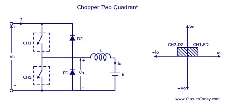
- Two quadrant operation can be achieved by giving gate pulse to CH1 and CH2 consecutively.
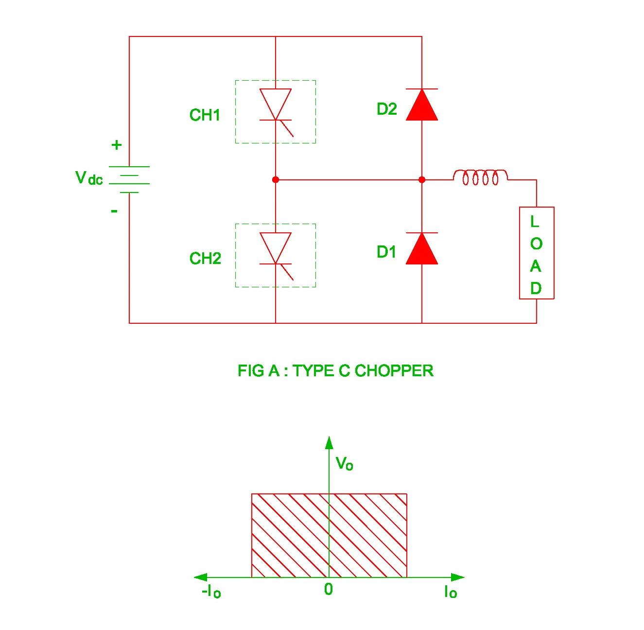
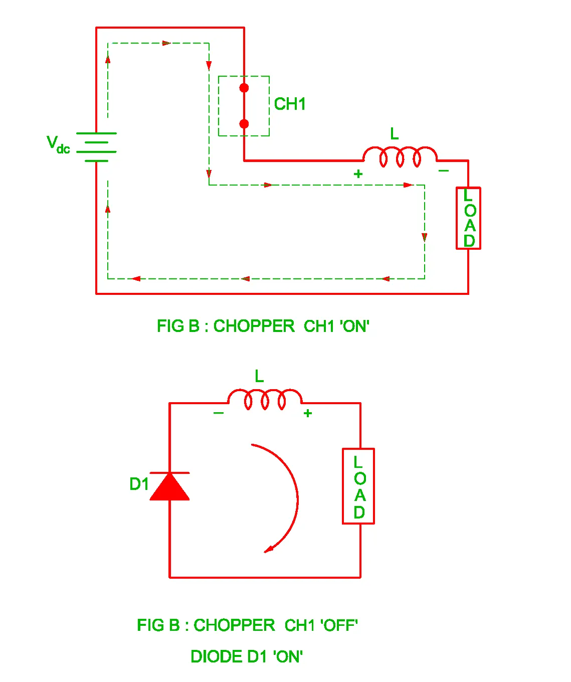
- When CH1 is on, input voltage appears across the load and current is flowing in forward direction(source to load).
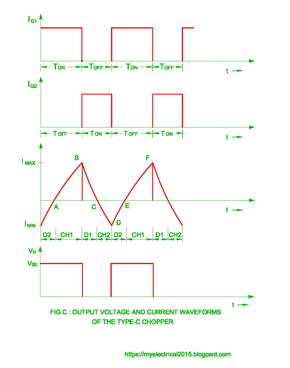
- Load current is increasing exponentially, till CH1 is on inductor is getting charged.(from poit A to B)
- When CH1 is turned off, the inductor forcely made Freewheeling diode(D1) to conduct and the current remains positive during while D1 is conducting.
- D1 will conduct(from point B to C) till inductor got discharged which results in load current to fall zero when Ldi/dt = Eb (point C), the output voltage is zero.
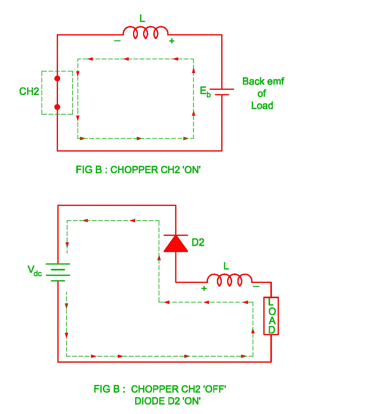
- When CH2 turned on, the inductor is getting charged in opppostie direction due to effect of back emf of load.(From point C to D)
- The current is flowing in opposite direction and output voltage is zero this time too.
- When CH2 is turned off, load inductor forcely made D2 to conduct and now load inductor is feeding back to source.(from D to E) Current direction is still negative.
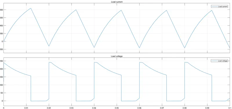
- The Output current and voltage waveform are shown below.
MODEL:
- To develop model of two quadrant chopper , take a look at image shown below.
- Input is fed by a DC source, Two switches are implemented by MOSFET.
- Make sure that both switch never operate at once to avoid short circuit.
- Add a diode in antiparallel manner across each MOSFET.
- Load is connected across Diode FD which helps output voltage to remain positive throughout the operation.
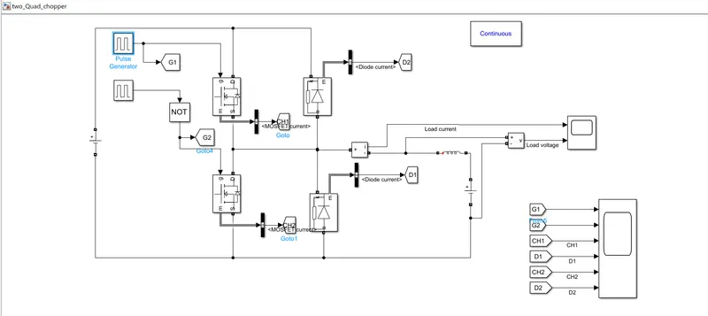
- Voltage and current measurement device are connected at load side to observe load curves.
- Indivisual currents of MOSFETs and Diodes are also being plotted.
RESULTS:
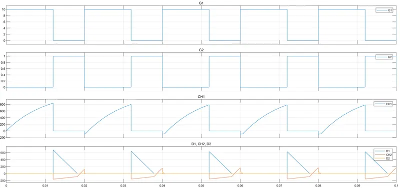
- G1 is gate signal for CH1 and G2 is gate signal for CH2.
- When Pulse for CH1 appears, there is exponential rise in load current as per the width of pulse.
- Then diode D1 is conducting just after when CH1 is turned off, the current from diode D1 can be seen falling till zero.
- There is Negative current flowing in circuit while CH2 is turned on, this time inductor is getting charged fron Back emf of Load itself.
- When CH2 is turned off, diode D2 started conducting, it will conduct till Ldi/di+Eb = Vs , and then Current reached to zero again.
Net load current and output voltage plot:
Challenge03: Explain in a brief about operation of BLDC motor:
- BLDC motor is the best alternative of a normal DC motor, it is used in such application where high speed, and high torque are required.
- It has many advantage over brushed DC motor like high power-to-weight ratio, high speed, nearly instantaneous control of speed (rpm) and torque, high efficiency, and low maintenance
- BLDC is controlled by an electronic circuit ,ESC(electronic speed conttroller) that's why also known as Electronically commutated Motor or Permanent magnet synchrounous motor.
Construction:
- In BLDC motor rotatary part maybe armature or permanent mangent based stator.
- There are two types of BLDC motor; 1). Outrunner BLDC 2).Inrunner BLDC.
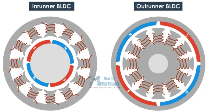
- Outrunner motor, 3 phase distributed armature is stationary and surrounded by PM rotor and in Inrunner BLDC motor, PM rotor is surrounded by 3 phase armature windings.
- The arrangement of rotor and armature is such that number of armature poles and Permanent magnets are kept unequal to avoid interlocking. For example in outrunner BLDC motor if there are 12 poles of armature winding then the number of permanent magnets are 14, vice versa in case of inrunner motor.
- In inrunner BLDC ,heat cab be easily disspipated as the armature windings are placed outside, but in outrunner motor the rotor with PM blocks are heat hence, there are holes can be seen in outrunner type BLDC motor.
WORKING:
- The speed control is achieved by current pulses send by electronic controller.
- The three phase windings are provided such that at a time only two phases are energised,such that if rotor is rotating clockwise the upcoming coil in rotor direction should attract the rotor and the preceding coil should repel it.
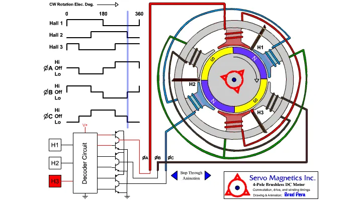
- To know which two phases are need to be energised, the exact position of rotor is required the position is determined by the Hall effect sensors present across each phase as shown in image above.
- Speed of motor depends upon the pulse width and the frequency of pulses, by controlling this frequency speed control of BLDC is achieved.