Week-7 Challenge: DC Motor Control
1. Speed control of a DC motor using BJT H-bridge :
H-Bridge Bipolar Junction Transistor(BJT) :
An H-bridge is an arrangement of transistors that allows a circuit full control over a standard electric DC motor. That is, an H-bridge allows a microcontroller, logic chip, or remote control to electronically command the motor to go forward, reverse, brake, and coast. It contains four switching elements with the load(generally, motor) at the centre in an H-like configuration as in fig 1.0. The basic operation of the H-bridge is given in the fig 1.1 and 1.2 below.
fig 1.0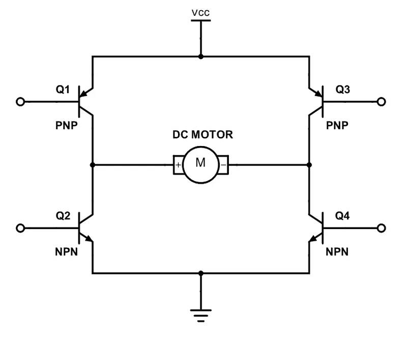 fig 1.1
 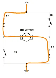 fig 1.2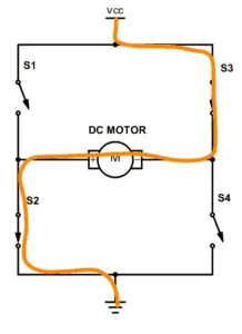
When a positive gate is applied, the switches Q1 and Q4 are turned on and the motor rotates in the forward direction as in the fig 1.1. During the change of positive to the negative supply where in this time period, the switches Q1 and Q4 are in the off condition. When the negative gate signal is given to the switches Q2 and Q3, they are turned on and the motor rotates in the reverse direction as in the fig 1.2. During the change of the negative to the positive supply where in this time period, the switches Q3 and Q4 are in the off condition. We cannot trigger the two switches of the same leg at the same time or simultaneously, as it creates a low resistance path and the switches gets damaged.
SIMULINK MODEL :
fig 1.3 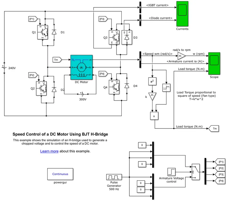
The Bipolar Junction Transistor(BJT), when used for the power switching applications operates as an Insulated Gate Bipolar Junction Transistor(BJT), when it is conducting, a forward voltage Vf is developed between the collector and the emitter(in the range of 1 V), therefore, the IGBT block can be used to model the BJT device. The IGBT block does not stimulate the gate current controlling the BJT or IGBT. The switch is controlled by a simulink signal
A. DESCRIPTION :
The DC motor used in this model is the present DC motor model(5 HP 24 V 1750 rpm). It stimulates a fan type load, where the load torque is proportional to the square of the speed. The armature mean voltage can be varied from 0-240 V, when the duty cycle is varied from 0-100 %. The H-bridge consists of four BJT/diode pairs(BJT stimulated by the IGBT models). The two transistors Q1 and Q4/Q2 and Q3 are turned on simulatneously. When Q1 and Q4 are fired, a positive vltage is applied to the motor and the diodes D2 and D3 operates as free-wheeling diodes when Q1 and Q4 are switched off. When Q2 and Q3 are fired, a negative voltage is applied to the motor and the diodes D1 and D4 operates as free-wheeling diodes when Q2 and Q3 are switched off.
RESULTS :
fig 1.4 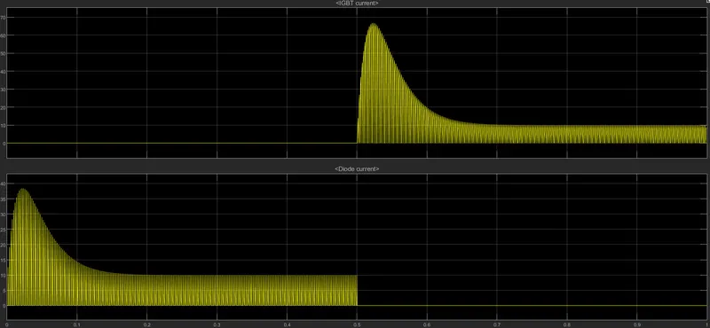
Here from the fig 1.4, the scope named 'Currents' provides the plots of the IGBT current and the diode current, flowing in the BJT Q3 and the Diode D3, where it is observed that, for 0-0.5 sec, the current flows from through the diode D3 and from 0.5-1 sec, the current flows through Q3. The motor starts in the positive direction with a duty cycle of 75%, ie, DC voltage is 180 V. At t=0.5 sec, the armature voltage is suddenly reversed and the motor runs in the negative direction.
fig 1.5 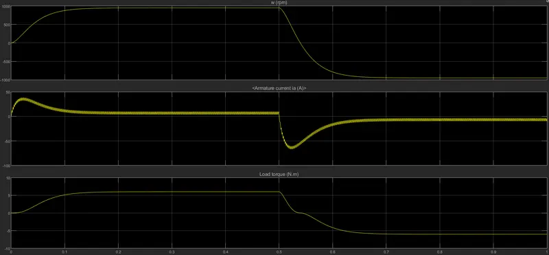
Here, form the fig 1.5, the 'Scope' shows the plots of the speed, armature current and the load torque, where it is observed that the;
- From the speed graph, the speed increases form 0-950 rpms and remains constantly in the 950 rpm mark till 0.5 sec and then decreases to -958 rpm at around 0.7 sec mark and remains constant.
- From the armature current graph, at the starting there is a sudden spike increase in the current form 0-37.5 A approximately at 0 sec and remains 0 till 0.5 sec mark, where the armature current increases in the negative direction from 0 to -66 A and again falls to about 0.
- From the load torque graph, it first increases to about 6 N-m at 0.1 sec and remains constant till 0.5 sec and then decreases to a negative value of -6 N-m and remains in tis value.
Also, it is seen that , as the voltage gets changed in the circuit, the speed of the motor also changes. In this transition of positive to negative direction of rotation, there is a surge in current due to the transient switching occuring in the circuit. As there is already current flowing in the circuit and on changing of the switches after 0.5 sec, the current adds to the change in the direction of the current and a surge is observed.
B. Comment on the armature current shoot-up from the scope results :
From the previous result, armature current shoot-up at the starting of the armature current a sudden rise in the waveform we had noticed. To reduce the sudden rise in the armature current we will reduce the duty cycle of the pulse width modulation from (75% to 50%) as in fig 1.6. The output of the wave form are shown below fig 1.7.
fig 1.6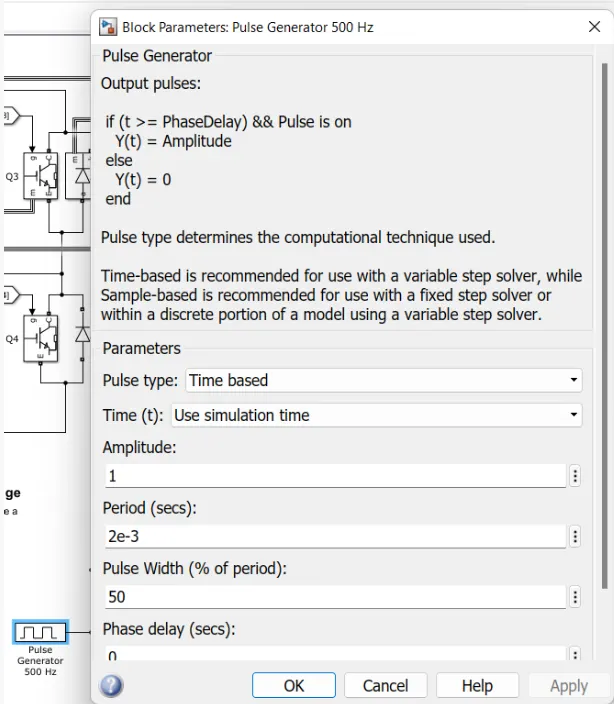 fig 1.7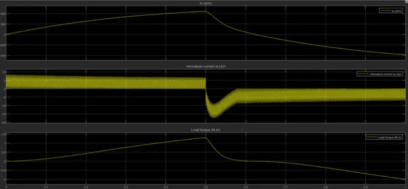
The difference between the above two graph, armature current in the second graph we observe that there is no sudden rise at the starting of the armature current. If we further reduced the pulse width modulation the negative of the rise will get reduced.
fig 1.8 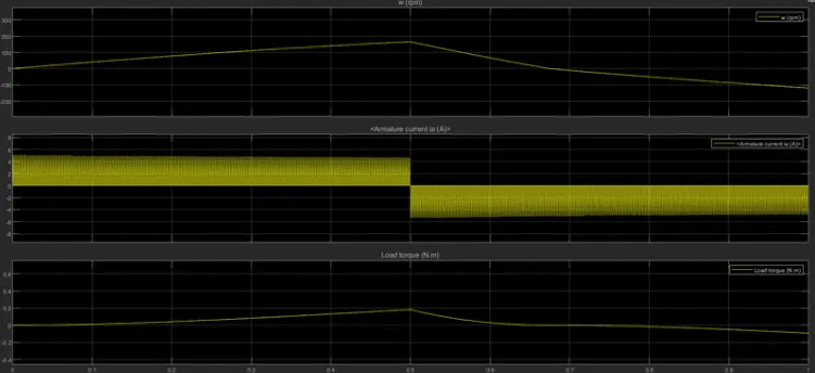
From the above graph it is clear that if we reduced the duty cycle ratio than a smooth variation in the output graph. The above graph PWM is 30% and motor details are default of the model. The torque and speed also varies smoothly(fig 1.8).
C. Refer to the help section of ‘The Four-Quadrant Chopper DC Drive (DC7) block’. Compare it with the H-bridge model :
The Four-Quadrant Chopper DC Drive (DC7) simulink model :
fig 1.9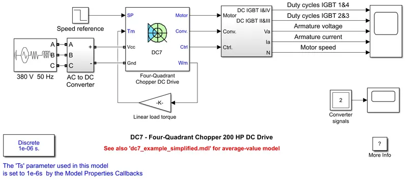
DC7 Connections :
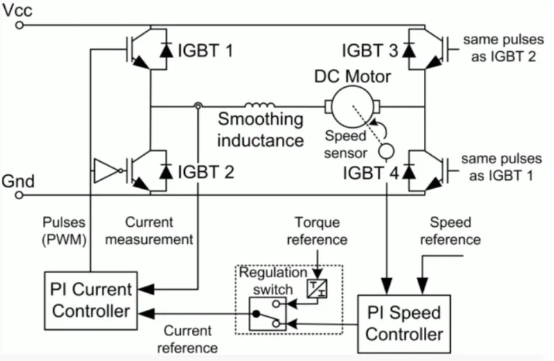
The Four-Quadrant chopper DC Drive (DC7) block represents a four-quadrant , DC-supplied, chopper(or DC-DC PWM converter) drive for DC motors. This drive features closed-loop speed control withj four-quadrant operation. The speed control loop outputs the reference armature current of the machine. Using a PI current controller, the chopper duty cycle corresponding to the commanded armature current is derived. This duty cycle is then compared with a sawtooth carrier signal to obtain the required PWM signals for the chopper.
WORKING :
Here four IGBT switches are used. Here pulses are given from PI current controller, that controls the pulses by comparing armature current measurement and current referance. Current reference can be generted by using regulation switch in that torque reference and PI speed controller pulses, that internally compared by speed of motor and reference speed mainly speed controlled by current controller. In this case four quadrant operations performed : Forward motoring mode, Forward regenerative braking mode : Q1,Q4 are ON and Q2,Q3 are in OFF and Reverse motoring mode, Reverse braking mode : Q2,Q3 are ON and Q1,Q4 are in OFF.
COMPARISON :
|
Sl. NO |
FOUR QUADRANT CHOPPER |
H-BRIDGE MODEL |
|
1 |
The motor can be operated in all the four different modes such as forward motoring, reverse motoring, forward braking, reverse braking. |
In this model, we have only two modes, forward motoring and reverse motoring. |
|
2 |
Regenerative braking can be achieved. |
Regenerative braking is not possible. |
|
3 |
Four quadrant chopper may have high switching frequency. |
H-bridge model have low switching frequency. |
|
4 |
The current values are chopped, not continuous and hence simulation takes less time. |
The current values are continuous. |
|
5 |
To change the direction of motor, current signals are interrupted with one another. |
To change the direction of motor, only the polarity of the current is changed. |
|
6 |
In this the vehicle control is better. |
The vehicle control is less. |
|
7 |
Four quadrant chopper is generally used in industrial application. |
H-bridge model used in robotics. |
2. TWO-QUADRANT CHOPPER USING SIMULINK(Refer to article - https://skill-lync.com/projects/multi-quadrant-operation-of-dc-motor-in-simulink) :
CIRCUIT DIAGRAM FOR TWO QUADRANT CHOPPER :
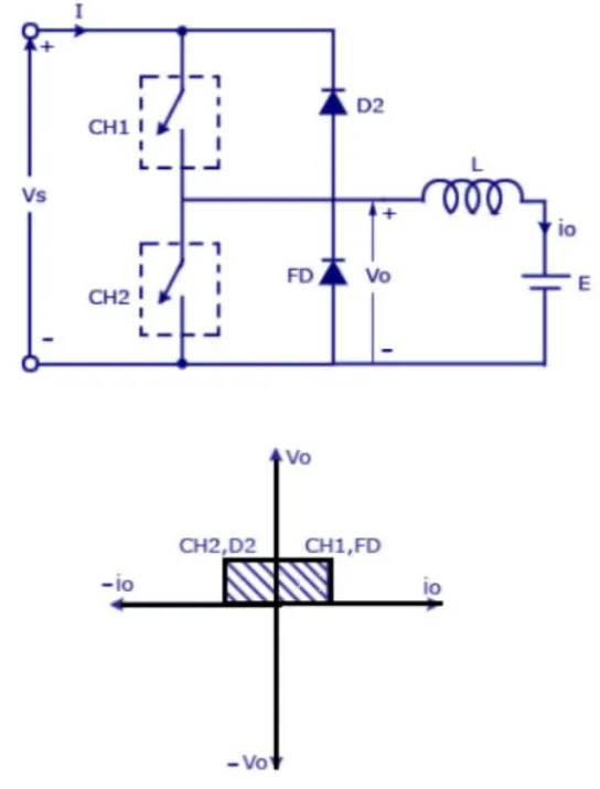
Two quadrant chopper is also called as type C chopper. Type C chopper is obtained by connecting type-A and type-B choppers in parallel. We will always get a positive output voltage Vo as the freewheeling diod FD is present across the load. When the chopper is on the freewheeling diode starts conducting and the output voltage Vo will be equal to Vs. The direction of the load current io will be reversed. The current io will flowing towards the source and it will be positive regardless the chopper is on or the FD conducts. The load current will be negative if the chopper is or the diode D2 conducts. We can say the chopper and FD operate together as type-A chopper in first quadrant. In the second quadrant , the chopper and D2 will operate together as type-B chopper.
The average voltage will be always positive but the average load current might be positive or negative. The power flow may be life the first quadrant operation, ie from source to load or from load to source like the second quadrant operation. The two choppers should not be turned on simultaneously as the combined action my cause a short circuit in supply lines. for regenerative braking and motoring these type of chopper configuration is used.
This is type C chopper the output of the voltage is positive and the output of the current is positive and negative.
SIMULINK MODEL :
fig 2.1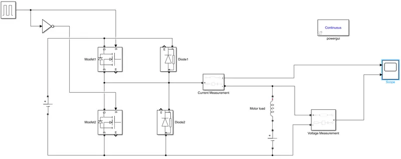
Let us take two MOSFET blocks and diode blocks and connect it as shown in circuit diagram(as in fig 2.1). The DC voltage source is connected as shown. Let the voltage of DC voltage source be 24 volts. Let us consider an series RLC block and select inductor L. thus block work as load(inductance i had taken here is 5e-3). To consider Motor load(LE), and DC voltage source 12 volts is also connected in series with inductor.
fig2.2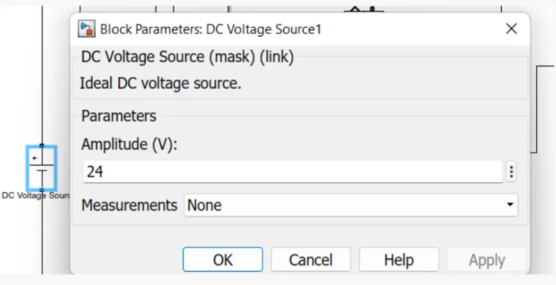 fig 2.3
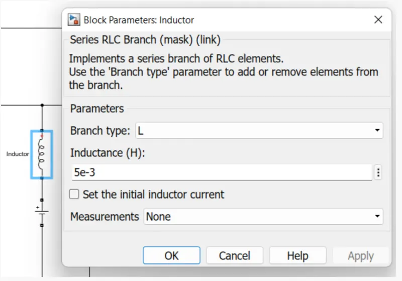 fig 2.4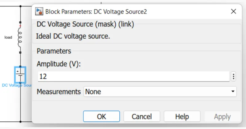
The pulse generator block is used to create pulses. The NOT gate is used in the model so that the two MOSFET will not get closed at the same time otherwise short circuit will occur. Due to the use of NOT gate, when one mosfet is ON the other mosfet will get OFF and when other mosfet is ON the first mosfet will get OFF. The amplitude of the pulse generator is kept 10 , so that we can clearly see the pulse at scope and let period be 0.02 seconds and let pulse width be 50%. Inductance taken here is 5e-3. Now we will run the model for 0.5 sec of sample and get an output result scope in fig 2.6.
fig 2.5 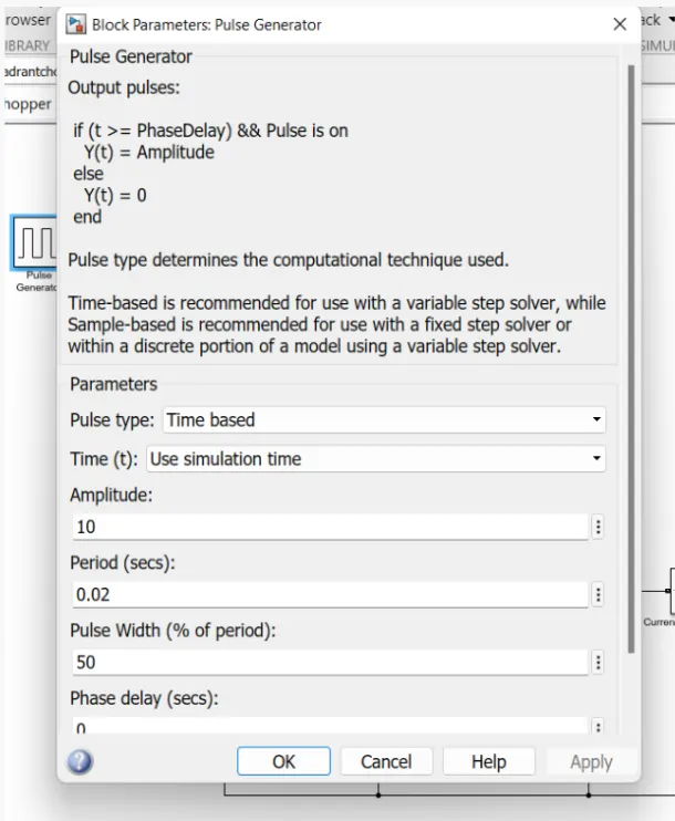
SCOPE RESULT :
The voltage wave is not less going less than zero, the minimum value of voltage is zero and maximum value is always in the positive direction. However in current waveform, the current increases and decreases. The current may be positive as well as negative. The output of the voltage waveform in positive half cycle and current waveform in positive and negative half cycle, this is the two quadrant operattion of Type-C chopper, the voltage is positive and current is positive and negative as shown in the fig 2.6.
fig 2.6 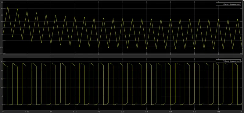
3. BRUSHLESS DC (BLDC) MOTOR :
A brushless DC electric motor(BLDC), also known as electronically commutated motor or synchronous DC motor, is a synchronous motor using a direct current electric power supply. A BLDC motor also known as permanent magnet synchromous motor(PMSM). There are two types of BLDC motors are present 1. 3-phase trapezoidal BLDC motor, 2. sinusidal type BLDC motor. Most of the BLDC motors are 3-phase type.
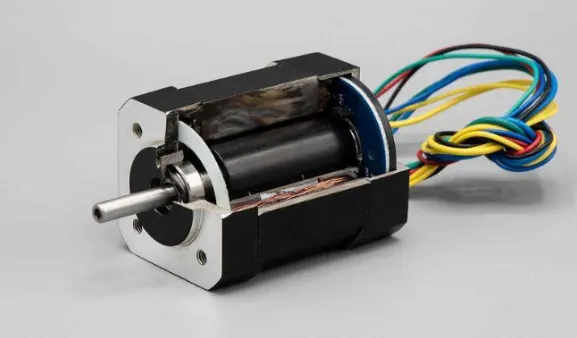
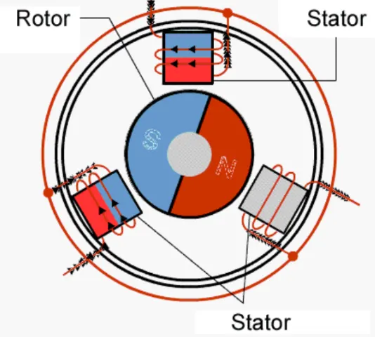
As shown in the above figure the BLDC motor has only two basic parts, rotor and stator. The rotor is the rotating part and has rotor magnets whereas stator is the stationary part and contains stator windings. In BLDC permanent magnets are attached in the rotor and move the electromagnets to the stator. The high power transistors are used to activate electromagnets for the shaft runs. The performance power distribution by using a solid-state circuit.
OPERATION :
There are 3 windings as you can see in the below image. Each of these phases are electrically 120 degrees apart from each other. The winding around the stator are wound such that current enters from the source an leaves back to complete the circuit. The decoder circuit works such that the 3 phases are active 120 degrees apart, as you can see in the below diagram(fig 2.1).
fig 2.1 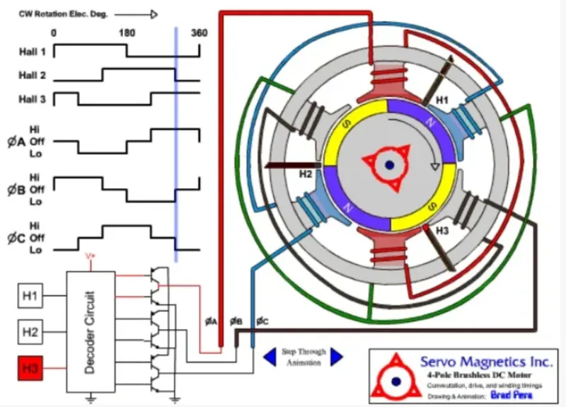
The semi-conductor switch has a duty cycle which creates a rough sinusoidal wave as output, which is then fed to the motor-stator windings and is spread in time in such a way that we create a RMF - Rotating Magnetic Field. Now, the rotor tries to follow this moving stator current and thus creating a motion.
ADVANTAGES OF BLDC MOTOR :
- The absence of brushes reduces the frequent replacement of brushes which reduces the maintenance cost.
- A Brushless DC motor has high-level control over the speed and position of the motor.
- The lifespan of a Brushless DC motor is higher than the brushed DC motor.
- Sparking is reduced due to the absence of brushes and there is a few chances of burnout due to sparking issues.
- A Brushless DC motor provides high torque to speed ratio which is best suited for robotics and medical applications.
- As there is no electromagnet in the Brushless DC motor hence the heating issue is being reduced.
- These motors are suitable to run either in a low load or no-load.
- As there are no brushes it produces less operating noise.
- These motors are used in electrical applications where less noise is required.
DISADVANTAGES OF BLDC MOTOR :
- Brushless DC motors are operated at relatively low speeds. Due to this low-speed vibrations occurs in the system.
- The cost of these motors is high.
- As these motors consist of a feedback loop the wiring and operation are not that simple.
- It requires an electronic switching controller to switch the voltage to the motor coils.
- As the Brushless DC motor doesn’t consist of the commutator, it will require some special electronic device.
- It needs three hall effect sensors to measure rotor position.
APLLICATIONS OF BLDC MOTOR :
- Brushless DC motors are used in hybrid vehicles, electric vehicles, and other electrical equipment.
- These motors are used in robotics for robotic arms.
- BLDC motors are used in computer hard drives and DVD players.
- These motors are used in fans, washing machines, dryers, pumps, blowers, and compressors.